
DATASHEET SEARCH SITE
Document overview
- Manufacturer or author: Provided By www.digicamel.com(FREE DATASHEET DOWNLOAD SITE)
- PDF pages: 17
Technical content
Description
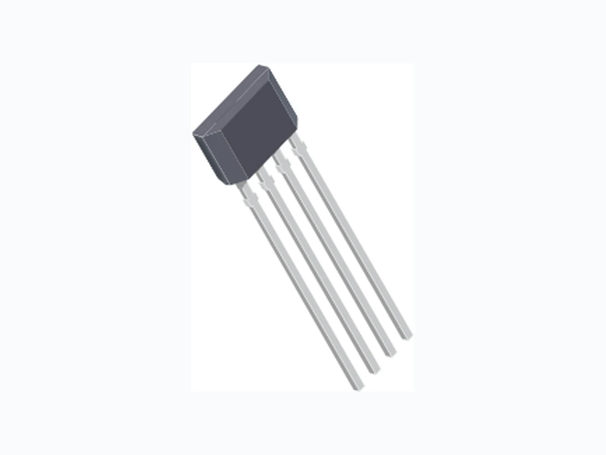
The A1230 is a dual-channel, bipolar switch with two Hall- effect sensing elements, each providing a separate digital output for speed and direction signal processing capability. The Hall elements are photolithographically aligned to better than 1 μm. Maintaining accurate mechanical location between the two active Hall elements eliminates the major manufacturing hurdle encountered in fine-pitch detection applications. The A1230 is a highly sensitive, temperature stable magnetic sensing device ideal for use in ring magnet based, speed and direction systems located in harsh automotive and industrial environments. The A1230 monolithic integrated circuit (IC) contains two independent Hall-effect bipolar switches located 1 mm apart. The digital outputs are out of phase so that the outputs are in quadrature when interfaced with the proper ring magnet design. This allows easy processing of speed and direction signals. Extremely low-drift amplifiers guarantee symmetry between the switches to maintain signal quadrature. The Allegro patented, high-frequency chopper-stabilization technique cancels offsets in each channel providing stable operation over the full specified temperature and voltage ranges. Additionally, the high-frequency chopping circuits allow an increased analog signal-to-noise ratio at the input of the digital A1230DS, Rev. 1 Features and Benefits ▪ Two matched Hall effect switches on a single substrate ▪ 1 mm Hall element spacing ▪ Superior temperature stability and industry-leading jitter performance through use of advanced chopper- stabilization topology ▪ Integrated regulator provides 3.3 V operation ▪ Integrated ESD protection from outputs and VCC to ground ▪ High sensitivity switchpoints ▪ Robust structure for EMC protection ▪ Solid-state reliability ▪ Reverse battery protection on supply and both output pins Ultra-Sensitive Dual-Channel Quadrature Hall-Effect Bipolar Switch Continued on the next page… Typical Application Not to scale A1230 Packages: 8-pin SOIC (suffix L), and 4-pin SIP (suffix K)
1 A1230
0.1 μF VOUTPUTB VOUTPUTA OUTPUTA OUTPUTB GND VCC 100 7 A A Resistor is optional depending on Conducted Immunity requirements
Ultra-Sensitive Dual-Channel Quadrature Hall-Effect Bipolar SwitchA1230 2Allegro MicroSystems, Inc.
115 Northeast Cutoff, Box 15036
Worcester, Massachusetts 01615-0036 (508) 853-5000 www.allegromicro.com comparators internal to the IC. As a result, the A1230 achieves industry-leading digital output jitter performance that is critical in high performance motor commutation applications. An on-chip regulator allows the use of this device over a wide operating voltage range. Post-assembly factory programming at Allegro provides sensitive switchpoints that are symmetrical between the two switches. The A1230 is available in a plastic 8-pin SOIC surface mount package (L) and a plastic 4-pin SIP (K). Both are available in a temperature range of –40°C to 150°C. Each package is lead (Pb) free, with 100% matte tin plated leadframe. Description (continued) Absolute Maximum Ratings Characteristic Symbol Notes Rating Units Supply Voltage V CC 26.5 V Reverse Battery Voltage V RCC –16 V Output Off Voltage V OUTPUT VCC V Output Sink Current I OUTPUT(Sink) Internally Limited – Magnetic Flux Density B Unlimited – Operating Ambient Temperature T A Range L –40 to 150 ºC Maximum Junction Temperature T J(max) 165 ºC Storage Temperature T stg –65 to 170 ºC Selection Guide Part Number Packing* Mounting Ambient, T A A1230LK-T Bulk, 98 pieces/bag 4-pin SIP through hole –40ºC to 150ºC A1230LLTR-T 13-in. reel, 3000 pieces/reel 8-pin SOIC surface mount *Contact Allegro for additional packing options.
Ultra-Sensitive Dual-Channel Quadrature Hall-Effect Bipolar SwitchA1230 3Allegro MicroSystems, Inc. Worcester, Massachusetts 01615-0036 (508) 853-5000 www.allegromicro.com Functional Block Diagram Pin-Out Diagrams 1 2 3 4 Package LPackage K Terminal List Table Pin Number Name Function Package K Package L 1 1 VCC Connects power supply to on-chip voltage regulator 2 2 OUTPUTA Output from E1 via fi rst Schmitt circuit 3 3 OUTPUTB Output from E2 via second Schmitt circuit 4 4 GND Terminal for ground connection – 5-8 NC No connection Amp Output Drive Amp Output Drive
2 Bit
4 Bit
Ultra-Sensitive Dual-Channel Quadrature Hall-Effect Bipolar SwitchA1230 4Allegro MicroSystems, Inc. Worcester, Massachusetts 01615-0036 (508) 853-5000 www.allegromicro.com OPERATING CHARACTERISTICS Valid over operating temperature ranges unless otherwise noted; typical data applies to VCC = 12 V, and TA = 25ºC Characteristic Symbol Test Conditions Min. Typ. Max. Unit 1
ELECTRICAL CHARACTERISTICS
Supply Voltage2 VCC Operating; TA ≤ 150°C 3.3 – 18 V Output Leakage Current I OUTPUT(OFF) Either output – < 1 10 μA Supply Current ICC(OFF) B < BRP(A) ,B < BRP(B) – 3.5 6.0 mA ICC(ON) B > BOP(A) ,B > BOP(B) – 4.5 6.0 mA Low Output Voltage V OUTPUT(ON) Both outputs; IOUTPUT(SINK) = 20 mA; B > BOP(A), B > BOP(B) – 160 500 mV Output Sink Current I OUTPUT(SINK) – – 20 mA Output Sink Current, Continuous3 IOUTPUT(SINK)C TJ < TJ(max) ,VOUTPUT = 12 V – – 70 mA Output Sink Current, Peak4 IOUTPUT(SINK)P t < 3 seconds – – 220 mA Chopping Frequency f C – 780 – kHz Output Rise Time t r CLOAD = 20 pF, RLOAD = 820 Ω – 1.8 – μs Output Fall Time t f CLOAD = 20 pF, RLOAD = 820 Ω – 1.2 – μs Power-On Time t ON B > 40 G or B < –40 G – 15 – μs Power-Off Time t OFF B > 40 G or B < –40 G – 25 – μs Power-On State POS B = 0 G – Low – – TRANSIENT PROTECTION CHARACTERISTICS Supply Zener Voltage V Z ICC = 9 mA, TA = 25°C 28 – – V Supply Zener Current5 IZ VS = 28 V – – 9.0 mA Reverse-Battery Current I RCC VRCC = –18 V, TJ < TJ(max) – 2 15 mA Continued on the next page...
Ultra-Sensitive Dual-Channel Quadrature Hall-Effect Bipolar SwitchA1230 5Allegro MicroSystems, Inc. Worcester, Massachusetts 01615-0036 (508) 853-5000 www.allegromicro.com MAGNETIC CHARACTERISTICS6 Operate Point: B > BOP BOP(A), BOP(B) – 7 30 G Release Point: B < BRP BRP(A), BRP(B) –30 –7 – G Hysteresis: BOP(A) – BRP(A), BOP(B) – BRP(B) BHYS(A), BHYS(B) 51 43 5 G Symmetry: Channel A, Channel B, BOP(A) + BRP(A), BOP(B) + BRP(B) SYMA, SYMB –35 – 35 G Operate Symmetry: BOP(A) – BOP(B) SYMAB(OP) –25 – 25 G Release Symmetry: BRP(A) – BRP(B) SYMAB(RP) –25 – 25 G 11 G (gauss) = 0.1 mT (millitesla). 2When operating at maximum voltage, never exceed maximum junction temperature, TJ(max). Refer to power derating curve charts. 3 Device will survive the current level specifi ed, but operation within magnetic specifi cation cannot be guaranteed. 4 Short circuit of the output to VCC is protected for the time duration specifi ed. 5 Maximum specifi cation limit is equivalent to ICC(max) + 3 mA. 6 Magnetic fl ux density, B, is indicated as a negative value for north-polarity magnetic fi elds, and as a positive value for south-polarity magnetic fi elds. This so-called algebraic convention supports arithmetic comparison of north and south polarity values, where the relative strength of the fi eld is indicated by the absolute value of B, and the sign indicates the polarity of the fi eld (for example, a –100 G fi eld and a 100 G fi eld have equivalent strength, but opposite polarity). OPERATING CHARACTERISTICS (continued) Valid over operating temperature ranges unless otherwise noted; typical data applies to VCC = 12 V, and TA = 25ºC Characteristic Symbol Test Conditions Min. Typ. Max. Unit 1 EMC Contact Allegro MicroSystems for EMC performance.
Ultra-Sensitive Dual-Channel Quadrature Hall-Effect Bipolar SwitchA1230 6Allegro MicroSystems, Inc. Worcester, Massachusetts 01615-0036 (508) 853-5000 www.allegromicro.com THERMAL CHARACTERISTICS may require derating at maximum conditions, see application information Characteristic Symbol Test Conditions* Value Units Package Thermal Resistance RθJA Package K, 1-layer PCB with copper limited to solder pads 177 ºC/W Package L-8 pin, 1-layer PCB with copper limited to solder pads 140 ºC/W Package L-8 pin, 4-layer PCB based on JEDEC standard 80 ºC/W *Additional thermal data available on the Allegro Web site. 20 40 60 80 100 120 180 140 160 Temperature (ºC) Maximum Allowable VCC (V) Power Derating Curve (RθJA = 140 ºC/W) Package L, 1-layer PCB (RθJA = 177 ºC/W) Package K, 1-layer PCB (RθJA = 80 ºC/W) Package L, 4-layer PCB VCC(min) VCC(max) 100 200 300 400 500 600 700 800 900 1000 1100 1200 1300 1400 1500 1600 1700 1800 1900 20 40 60 80 100 120 140 160 180 Temperature, TA (°C) Power Dissipation, PD (mW) Power Dissipation versus Temperature θJA = 140 ºC/W) Package L, 1-layer PCB θJA = 177 ºC/W) Package K, 1-lay er PCB θJA = 8 0 ºC/W) Package L, 4-layer PCB
Ultra-Sensitive Dual-Channel Quadrature Hall-Effect Bipolar SwitchA1230 7Allegro MicroSystems, Inc. Worcester, Massachusetts 01615-0036 (508) 853-5000 www.allegromicro.com Electrical Operating Characteristics 0.0 1.0 2.0 3.0 4.0 5.0 6.0 7.0 8.0 0 5 10 15 20 -40 150 0.0 1.0 2.0 3.0 4.0 5.0 6.0 7.0 8.0 -50 0 50 100 150 200 3.3 0.0 1.0 2.0 3.0 4.0 5.0 6.0 7.0 8.0 0 5 10 15 20 -40 150 0.0 1.0 2.0 3.0 4.0 5.0 6.0 7.0 8.0 -50 0 50 100 150 200 3.3 100 150 200 250 300 350 400 450 500 -50 0 50 100 150 200 3.3 3.3 ICC(OFF) ICC(ON) ICC(OFF) ICC(ON) Current (mA) Current (mA) VCC (V) TA (°C) VCC (V) TA (°C) Ch. A Ch. B VCC (V) VCC (V) Temperature ( C) VOUTPUT(on) Current (mA) Current (mA) VCC (V) Voltage (mV) Temperature ( C) Temperature ( C)
Ultra-Sensitive Dual-Channel Quadrature Hall-Effect Bipolar SwitchA1230 8Allegro MicroSystems, Inc. Worcester, Massachusetts 01615-0036 (508) 853-5000 www.allegromicro.com 5.0 10.0 15.0 20.0 25.0 30.0 35.0 0 5 10 15 20 -4 0 150 -4 0 150 5.0 10.0 15.0 20.0 25.0 30.0 35.0 -50 0 50 100 150 200 -30.0 -20.0 -10.0 0.0 10.0 20.0 30.0 -50 0 50 100 150 200 -30.0 -20.0 -10.0 0.0 10.0 20.0 30.0 0 5 10 15 20 -30.0 -20.0 -10.0 0.0 10.0 20.0 30.0 -50 0 50 100 150 200 -30.0 -20.0 -10.0 0.0 10.0 20.0 30.0 0 5 10 15 20 TA (°C) TA (°C) -4 0 150 -4 0 150 BOP BRP -4 0 150 -4 0 150 3.3 3.3 BOP BRP VCC (V) 3.3 3.3 BOP BRP VCC (V) 3.3 3.3 BOP BRP VCC (V) BOP BRP TA (°C) Ch. A Ch. B Temperature (oC) VCC (V) Temperature (oC) Channel A, BOP and BRP Switchpoint (G) VCC (V) Switchpoint (G) Channel B, BOP and BRPChannel B, BOP and BRP Switchpoint (G) Switchpoint (G) Channels A and B, BHYS(A) and BHYS(B) Channels A and B, BHYS(A) and BHYS(B) BOP - BRP (G) BOP - BRP (G) VCC (V) Temperature (oC) Channel A, BOP and BRP Magnetic Operating Characteristics Additional magnetic characteristics on next page
Ultra-Sensitive Dual-Channel Quadrature Hall-Effect Bipolar SwitchA1230 9Allegro MicroSystems, Inc. Worcester, Massachusetts 01615-0036 (508) 853-5000 www.allegromicro.com Magnetic Operating Characteristics Additional magnetic characteristics on next page -25.0 -20.0 -15.0 -10.0 -5.0 0.0 5.0 10.0 15.0 20.0 25.0 0 5 10 15 20 -40 150 -25.0 -20.0 -15.0 -10.0 -5.0 0.0 5.0 10.0 15.0 20.0 25.0 -50 0 50 100 150 200 3.3 -25.0 -20.0 -15.0 -10.0 -5.0 0.0 5.0 10.0 15.0 20.0 25.0 0 5 10 15 20 -40 150 -25.0 -20.0 -15.0 -10.0 -5.0 0.0 5.0 10.0 15.0 20.0 25.0 -50 0 50 100 150 200 3.3 VCC (V) TA (°C) VCC (V) TA (°C) VCC (V) Temperature (oC) VCC (V) Temperature (oC) BOP Symmetry, SYMAB(OP) BRP Symmetry, SYMAB(RP) BOP Symmetry, SYMAB(OP) BRP Symmetry, SYMAB(RP) Ch. A - Ch. B (G) Ch. A - Ch. B (G) Ch. A - Ch. B (G) Ch. A - Ch. B (G)
Ultra-Sensitive Dual-Channel Quadrature Hall-Effect Bipolar SwitchA1230 10Allegro MicroSystems, Inc. Worcester, Massachusetts 01615-0036 (508) 853-5000 www.allegromicro.com Magnetic Operating Characteristics -35.0 -25.0 -15.0 -5.0 5.0 15.0 25.0 35.0 -50 0 50 100 150 200 3.3 -35.0 -25.0 -15.0 -5.0 5.0 15.0 25.0 35.0 0 5 10 15 20 -40 150 -35.0 -25.0 -15.0 -5.0 5.0 15.0 25.0 35.0 -50 0 50 100 150 200 3.3 -35.0 -25.0 -15.0 -5.0 5.0 15.0 25.0 35.0 -40 150 0 5 10 15 20 TA (°C) VCC (V) TA (°C) VCC (V) VCC (V) Temperature (°C) Channel A Symmetry, SYMA Channel B Symmetry, SYMB Channel A Symmetry, SYMA Channel B Symmetry, SYMB VCC (V) BOP + BRP (G) BOP + BRP (G) BOP + BRP (G) BOP + BRP (G) Temperature (°C)
Ultra-Sensitive Dual-Channel Quadrature Hall-Effect Bipolar SwitchA1230 11Allegro MicroSystems, Inc. Worcester, Massachusetts 01615-0036 (508) 853-5000 www.allegromicro.com Functional Description Chopper-Stabilized Technique A limiting factor for switchpoint accuracy when using Hall effect technology is the small signal voltage developed across the Hall plate. This voltage is proportionally small relative to the offset that can be produced at the output of the Hall IC. This makes it diffi cult to process the signal and maintain an accurate, reliable output over the specifi ed temperature and voltage range. Chopper-stabilization is a unique approach used to minimize Hall offset on the chip. The Allegro patented technique, dynamic quadrature offset cancellation, removes key sources of the output drift induced by temperature and package stress. This offset reduction technique is based on a signal modulation-demodula- tion process. The undesired offset signal is separated from the magnetically induced signal in the frequency domain through modulation. The subsequent demodulation acts as a modulation process for the offset causing the magnetically induced signal to recover its original spectrum at baseband while the DC offset becomes a high frequency signal. Then, using a low-pass fi lter the signal passes while the modulated DC offset is suppressed. Allegro’s new innovative chopper-stabilization technique uses a high frequency clock. This chopper-stabilization approach de- sensitizes the IC to temperature and stress. The high-frequency operation also allows a greater sampling rate that produces higher accuracy and faster signal processing capability. Additionally, fi ltering is more effective and results in a lower noise analog signal at the input to the Schmitt trigger. Therefore, this high- frequency chopping technique reduces jitter, also known as 360° repeatability, can be induced on the output signal. The sample- and-hold process, used by the demodulator to store and recover the signal, can slightly degrade the signal to noise ratio. This is because the process generates replicas of the noise spectrum at the baseband, causing a decrease in jitter performance. However, the improvement in switchpoint performance, resulting from the reduc- tion of the effects of thermal and mechanical stress, outweighs the degradation in the signal to noise ratio. This technique produces devices that have an extremely stable quiescent Hall output voltage, are immune to thermal stress, and have precise recoverability after temperature cycling. This technique is made possible through the use of a BiCMOS process which allows the use of low offset and low noise amplifi ers in combination with high-density logic integration and sample and hold circuits. Chopper stabilization circuit (dynamic quadrature offset cancellation) Amp Regulator Low- Pass Filter Sample and Hold
Ultra-Sensitive Dual-Channel Quadrature Hall-Effect Bipolar SwitchA1230 12Allegro MicroSystems, Inc. Worcester, Massachusetts 01615-0036 (508) 853-5000 www.allegromicro.com Channel A Magnetic Field at Hall Element E1 Channel A Output Signal at OUTPUTA Channel B Output Signal at OUTPUTB Channel B Magnetic Field at Hall Element E2 Typical Applications Operation Quadrature output signal confi guration. The outputs of the two output channels have a phase difference of 90º when used with a properly designed magnet that has an optimal pole pitch of twice the Hall element spacing of 1.0 mm. BOP BRP BHYS VOUTPUT(OFF) VOUTPUT VOUTPUT(ON)(sat) Switch to Low Switch to High Output voltage in relation to magnetic fl ux density received. Output on each channel independently follows the same pattern of transition through B OP followed by transition through BRP.
Ultra-Sensitive Dual-Channel Quadrature Hall-Effect Bipolar SwitchA1230 13Allegro MicroSystems, Inc. Worcester, Massachusetts 01615-0036 (508) 853-5000 www.allegromicro.com Regulated supply 0.1 μF VOUTPUTB VOUTPUTA OUTPUTA OUTPUTB GND VCC 100 7 A A Resistor is optional and is likely not needed for 12 V or 40 V clamped systems 0.1 μF 100 7 This device requires minimal protection circuitry during operation with a low-voltage regulated line. The on-chip voltage regulator provides immunity to power supply variations between 3.3 and 18 V . Because the device has open-drain outputs, pull-up resistors must be included. If protection against coupled and injected noise is required, then a simple low-pass fi lter on the supply (RC) and a fi ltering capacitor on each of the outputs may also be needed, as shown in the unregulated supply diagram. For applications in which the device receives its power from unregulated sources, such as a car battery, full protection is generally required to protect the device against supply-side transients. Specifi cations for such transients vary for each application, so the design of the protection circuit should be optimized for each application. For example, the circuit shown in the unregulated supply diagram includes a Zener diode that offers high voltage load-dump protection and noise fi ltering by means of a series resistor and capacitor. In addition, it includes a series diode that protects against high-volt- age reverse battery conditions. Unregulated supply Typical Applications Circuits
Ultra-Sensitive Dual-Channel Quadrature Hall-Effect Bipolar SwitchA1230 14Allegro MicroSystems, Inc. Worcester, Massachusetts 01615-0036 (508) 853-5000 www.allegromicro.com The device must be operated below the maximum junction temperature of the device, TJ(max) . Under certain combina- tions of peak conditions, reliable operation may require derating supplied power or improving the heat dissipation properties of the application. This section presents a procedure for correlating factors affecting operating T J. (Thermal data is also available on the Allegro MicroSystems Web site.) The Package Thermal Resistance, RJA, is a fi gure of merit sum- marizing the ability of the application and the device to dissipate heat from the junction (die), through all paths to the ambient air. Its primary component is the Effective Thermal Conductivity, K, of the printed circuit board, including adjacent devices and traces. Radiation from the die through the device case, R JC, is relatively small component of RJA. Ambient air temperature, TA, and air motion are signifi cant external factors, damped by overmolding. The effect of varying power levels (Power Dissipation, PD), can be estimated. The following formulas represent the fundamental relationships used to estimate T J, at PD. P D = VIN × IIN (1) T J = TA + ΔT (3) For example, given common conditions such as: TA= 25°C, VCC = 12 V, ICC = 4 mA, and RJA = 140 °C/W, then: P D = VCC × ICC = 12 V × 4 mA = 48 mW T = PD × RJA = 48 mW × 140 °C/W = 7°C A worst-case estimate, PD(max) , represents the maximum allow- able power level, without exceeding TJ(max) , at a selected RJA and TA. Example: Reliability for VCC at TA = 150°C, package L, using a single-layer PCB. Observe the worst-case ratings for the device, specifi cally: RJA = 140°C/W, TJ(max) = 165°C, VCC(max) = 18 V , and ICC(max) = 6 mA. Calculate the maximum allowable power level, PD(max) . First, invert equation 3: Tmax = TJ(max) – TA = 165 °C – 150 °C = 15 °C This provides the allowable increase to TJ resulting from internal power dissipation. Then, invert equation 2: PD(max) = Tmax ÷ RJA = 15°C ÷ 140°C/W = 107 mW Finally, invert equation 1 with respect to voltage: VCC(est) = PD(max) ÷ ICC(max) = 107 mW ÷ 6 mA = 18 V The result indicates that, at TA, the application and device can dissipate adequate amounts of heat at voltages ≤VCC(est) . Compare VCC(est) to VCC(max) . If VCC(est) ≤ VCC(max) , then reliable operation between VCC(est) and VCC(max) requires enhanced RJA. If VCC(est) ≥ VCC(max) , then operation between VCC(est) and VCC(max) is reliable under these condi- tions. Power Derating
Ultra-Sensitive Dual-Channel Quadrature Hall-Effect Bipolar SwitchA1230 15Allegro MicroSystems, Inc. Worcester, Massachusetts 01615-0036 (508) 853-5000 www.allegromicro.com Package K, 4-pin SIP 24 31 E1 E2 2.101.00
0.84 REF
1.27 NOM
2.16 MAX 0.51 REF 45° 45° C Hall elements (E1 and E2); not to scale B 1.32 Gate and tie bar burr area A B C Dambar removal protrusion (8X) A D E EE E D Active Area Depth, 0.43 mm REF For Reference Only; not for tooling use (reference DWG-9010) Dimensions in millimeters Dimensions exclusive of mold flash, gate burrs, and dambar protrusions Exact case and lead configuration at supplier discretion within limits shown Standard Branding Reference View N = Device part number Y = Last two digits of year of manufacture W = Week of manufacture Mold Ejector Pin Indent Branded Face YYWW NNNN 5.21 +0.08 –0.05 0.38 +0.06 –0.03 3.43 +0.08 –0.05 0.41 +0.07 –0.05 14.73 ±0.51 1.55 ±0.05 Branding scale and appearance at supplier discretion
Ultra-Sensitive Dual-Channel Quadrature Hall-Effect Bipolar SwitchA1230 16Allegro MicroSystems, Inc. Worcester, Massachusetts 01615-0036 (508) 853-5000 www.allegromicro.com CSEATING PLANE
1.27 BSC
A Terminal #1 mark area B Reference land pattern layout (reference IPC7351 SOIC127P600X175-8M); all pads a minimum of 0.20 mm from all adjacent pads; adjust as necessary to meet application process requirements and PCB layout tolerances PCB Layout Reference View B CActive Area Depth, 0.40 mm REF D C A B Branding scale and appearance at supplier discretion C 0.65 1.27 5.60 1.75 C0.10
0.25 BSC
1.04 REF
For Reference Only; not for tooling use (reference DWG-9204) Dimensions in millimeters Dimensions exclusive of mold flash, gate burrs, and dambar protrusions Exact case and lead configuration at supplier discretion within limits shown 4.90 ±0.10 3.90 ±0.10 0.41 ±0.10 6.00 ±0.20 0.21 ±0.04 0.84 +0.43 –0.44 0.15 +0.10 –0.05 1.62 +0.13 –0.27 Standard Branding Reference View NNNNNNN LLLL N = Device part number = Supplier emblem Y = Last two digits of year of manufacture W = Week of manufacture L = Lot number YYWW 1.95 1.00 1.95 D D D E1 E2 Package L, 8-pin SOICN
Ultra-Sensitive Dual-Channel Quadrature Hall-Effect Bipolar SwitchA1230 17Allegro MicroSystems, Inc. Worcester, Massachusetts 01615-0036 (508) 853-5000 www.allegromicro.com Copyright ©2010-2012, Allegro MicroSystems, Inc. Allegro MicroSystems, Inc. reserves the right to make, from time to time, such de par tures from the detail spec i fi ca tions as may be required to per- mit improvements in the per for mance, reliability, or manufacturability of its products. Before placing an order, the user is cautioned to verify that the information being relied upon is current. Allegro’s products are not to be used in life support devices or systems, if a failure of an Allegro product can reasonably be expected to cause the failure of that life support device or system, or to affect the safety or effectiveness of that device or system. The in for ma tion in clud ed herein is believed to be ac cu rate and reliable. How ev er, Allegro MicroSystems, Inc. assumes no re spon si bil i ty for its use; nor for any in fringe ment of patents or other rights of third parties which may result from its use. For the latest version of this document, visit our website: www.allegromicro.com
Revision History
Revision Revision Date Description of Revision Rev. 1 July 9, 2012 Update regulator description