
A1205 ALLEGRO
Document overview
- Manufacturer or author: Provided By www.digicamel.com(FREE DATASHEET DOWNLOAD SITE)
- PDF pages: 12
Technical content
Description
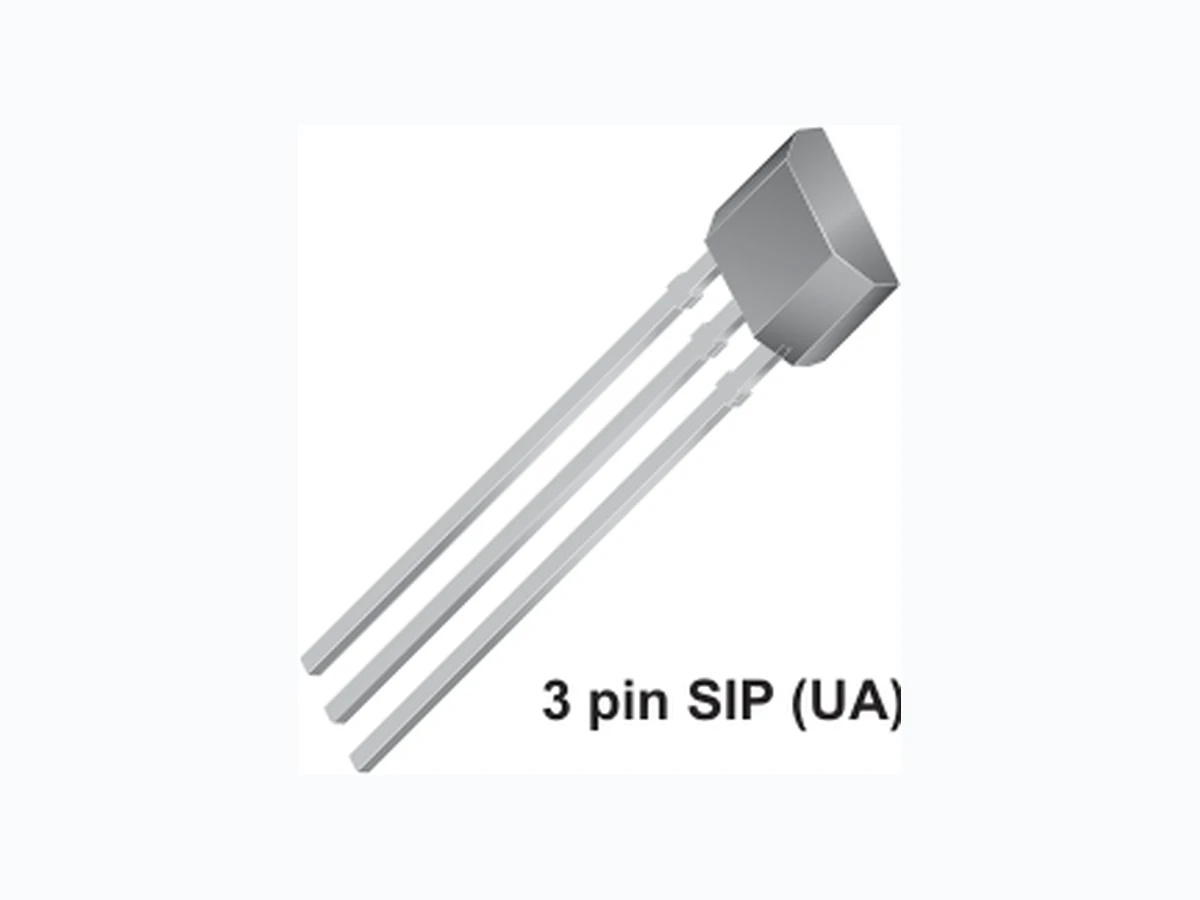
The Allegro ® A1205 Hall-effect bipolar switch is a next- generation replacement and extension of the popular Allegro A3134 bipolar switch. The A1205 has identical specifications as the A1201 but is recommended for applications that require pulsing V CC to conserve power. For standard applications, where V CC is constant, please refer to the A1201 through A1204 devices. Overall, the A120x family, produced with BiCMOS technology, consists of continuous-time devices that feature fast power- on time and low-noise operation. Device programming is performed after packaging to ensure increased switchpoint accuracy by eliminating offsets that can be induced by package stress. Unique Hall element geometries and low- offset amplifiers help to minimize noise and to reduce the residual offset voltage normally caused by device overmolding, temperature excursions, and thermal stress. The A120x Hall-effect bipolar switches include the following on a single silicon chip: voltage regulator, Hall-voltage generator, A1205-DS, Rev. 1 Features and Benefits ▪ Ideal for applications that require pulsing VCC to conserve power ▪ Continuous-time operation ▫ Fast power-on time ▫ Low noise ▪ Stable operation over full operating temperature range ▪ Reverse battery protection ▪ Solid-state reliability ▪ Factory-programmed at end-of-line for optimum performance ▪ Robust EMC performance ▪ High ESD rating ▪ Regulator stability without a bypass capacitor Continuous-Time Bipolar Switch Continued on the next page… Packages: Functional Block Diagram Not to scale A1205 3 pin SOT23W (LH) 3 pin SIP (UA) Amp Regulator GND VCC VOUT OffsetGain Trim Control To all subcircuits
Continuous-Time Bipolar SwitchA1205 2Allegro MicroSystems, Inc.
115 Northeast Cutoff, Box 15036
Worcester, Massachusetts 01615-0036 (508) 853-5000 www.allegromicro.com Selection Guide Part Number Packing* Mounting Ambient, TA BRP (Min) BOP (Max) A1205ELHLT-T 7-in. reel, 3000 pieces/reel 3-pin SOT23W surface mount –40ºC to 85ºC –50 50 A1205EUA-T Bulk, 500 pieces/bag 3-pin SIP through hole A1205LLHLT-T 7-in. reel, 3000 pieces/reel 3-pin SOT23W surface mount –40ºC to 150ºC A1205LUA-T Bulk, 500 pieces/bag 3-pin SIP through hole *Contact Allegro for additional packing options. Description (continued) Absolute Maximum Ratings Characteristic Symbol Notes Rating Units Supply Voltage VCC 30 V Reverse Supply Voltage VRCC –30 V Output Off Voltage VOUT 30 V Reverse Output Voltage VROUT –0.5 V Output Current Sink IOUTSINK 25 mA Magnetic Flux Density B Unlimited G Operating Ambient Temperature TA Range E –40 to 85 ºC Range L –40 to 150 ºC Maximum Junction Temperature TJ(max) 165 ºC Storage Temperature Tstg –65 to 170 ºC small-signal amplifier, Schmitt trigger, and NMOS output transistor. The integrated voltage regulator permits operation from 3.8 to 24 V . The extensive on-board protection circuitry makes possible a ±30 V absolute maximum voltage rating for superior protection in automotive and motor commutation applications, without adding external components. The small geometries of the BiCMOS process allow these devices to be provided in ultrasmall packages. The package styles available provide magnetically optimized solutions for most applications. package, while package UA is a three-lead ultramini SIP for through- hole mounting. Each package is lead (Pb) free, with 100% matte tin plated leadframes.
Continuous-Time Bipolar SwitchA1205 3Allegro MicroSystems, Inc. Worcester, Massachusetts 01615-0036 (508) 853-5000 www.allegromicro.com OPERATING CHARACTERISTICS over full operating voltage and ambient temperature ranges, unless otherwise noted Characteristic Symbol Test Conditions Min. Typ. Max. Units
Electrical Characteristics
Supply Voltage1 VCC Operating, TJ < 165°C 3.8 – 24 V Output Leakage Current IOUTOFF VOUT = 24 V, B < BRP – – 10 µA Output On Voltage VOUT(SAT) IOUT = 20 mA, B > BOP – 215 400 mV Power-On Time2 tPO Slew rate (dVCC/dt) < 2.5 V/μs, B > BOP + 5 G or B < BRP – 5 G – – 4 µs Output Rise Time3 tr VCC = 12 V, RLOAD = 820 Ω, CS = 12 pF – – 2 µs Output Fall Time3 tf VCC = 12 V, RLOAD = 820 Ω, CS = 12 pF – – 2 µs Supply Current ICCON B > BOP – 3.8 7.5 mA ICCOFF B < BRP – 3.5 7.5 mA Reverse Battery Current IRCC VRCC = –30 V – – –10 mA Supply Zener Clamp Voltage VZ ICC = 30 mA; TA = 25°C 32 – 40 V Supply Zener Current IZ VZ = 32 V; TA = 25°C – – 30 mA Magnetic Characteristics4 Operate Point BOP South pole adjacent to branded face of device –40 15 50 G Release Point BRP North pole adjacent to branded face of device –50 –15 40 G Hysteresis BHYS BOP – BRP 5 30 55 G 1 Maximum voltage must be adjusted for power dissipation and junction temperature, see Power Derating section. 2 For VCC slew rates greater than 2.5 V/μs, and TA = 150°C, the Power-On Time can reach its maximum value. 3 CS =oscilloscope probe capacitance. 4 Magnetic flux density, B, is indicated as a negative value for north-polarity magnetic fields, and as a positive value for south-polarity magnetic fields. This so-called algebraic convention supports arithmetic comparison of north and south polarity values, where the relative strength of the field is indicated by the absolute value of B, and the sign indicates the polarity of the field (for example, a –100 G field and a 100 G field have equivalent strength, but opposite polarity). Reference to the magnetic field polarity is with respect to the beveled face of the device. DEVICE QUALIFICATION PROGRAM Contact Allegro for information. EMC (Electromagnetic Compatibility) REQUIREMENTS Contact Allegro for information.
Continuous-Time Bipolar SwitchA1205 4Allegro MicroSystems, Inc. Worcester, Massachusetts 01615-0036 (508) 853-5000 www.allegromicro.com THERMAL CHARACTERISTICS may require derating at maximum conditions, see application information Characteristic Symbol Test Conditions* Value Units Package Thermal Resistance RθJA Package LH, 1-layer PCB with copper limited to solder pads 228 ºC/W Package LH, 2-layer PCB with 0.463 in.2 of copper area each side connected by thermal vias 110 ºC/W Package UA, 1-layer PCB with copper limited to solder pads 165 ºC/W *Additional thermal information available on Allegro Web site. 20 40 60 80 100 120 140 160 180 Maximum Allowable VCC (V) TJ(max) = 165ºC; ICC = ICC(max) Power Derating Curve (R JA = 228 ºC/W) Package LH, 1-layer PCB (R JA = 110 ºC/W) Package LH, 2-layer PCB (R JA = 165 ºC/W) Package UA, 1-layer PCB VCC(min) VCC(max) 100 200 300 400 500 600 700 800 900 1000 1100 1200 1300 1400 1500 1600 1700 1800 1900 20 40 60 80 100 120 140 160 180 Temperature (°C) Power Dissipation, PD (mW) Power Dissipation versus Ambient Temperature (RθJA = 165 ºC/W) 1-layer PCB, Package UA (RθJA = 228 ºC/W) 1-layer PCB, Package LH θJA =110 ºC/W) 2-layer PCB, Package LH
Continuous-Time Bipolar SwitchA1205 5Allegro MicroSystems, Inc. Worcester, Massachusetts 01615-0036 (508) 853-5000 www.allegromicro.com Characteristic Data –50 0 50 100 150 0 5 10 15 20 25 –50 0 50 100 150 0 5 10 15 20 25 100 150 200 250 300 350 –50 0 50 100 150 0 5 10 15 20 25 100 150 200 250 300 350 TA (°C) Supply Current (On) versus Ambient Temperature VCC (V) ICCON (mA) 24 3.8 TA (°C) Supply Current (Off) versus Ambient Temperature VCC (V) ICCOFF (mA) 24 3.8 ILOAD = 20 mA ILOAD = 20 mA TA (°C) Output Voltage (On) versus Ambient Temperature VCC (V) VOUT(SAT) (mV) 3.8 Supply Current (On) versus Supply Voltage TA (°C) ICCON (mA) VCC (V) –40 150 Supply Current (Off) versus Supply Voltage TA (°C) ICCOFF (mA) VCC (V) –40 150 Output Voltage (On) versus Supply Voltage TA (°C) VOUT(SAT) (mV) VCC (V) –40 150 1.0 2.0 3.0 4.0 5.0 7.0 6.0 8.0 1.0 2.0 3.0 4.0 5.0 7.0 6.0 8.0 1.0 2.0 3.0 4.0 5.0 7.0 6.0 8.0 1.0 2.0 3.0 4.0 5.0 7.0 6.0 8.0
Continuous-Time Bipolar SwitchA1205 6Allegro MicroSystems, Inc. Worcester, Massachusetts 01615-0036 (508) 853-5000 www.allegromicro.com -40 -30 -20 -10 -50 0 50 100 150 -40 -30 -20 0 5 10 15 20 25 -50 -40 -30 -20 -10 -50 0 50 100 150 -50 -40 -30 -20 -10 0 5 10 15 20 25 -50 0 50 100 150 0 5 10 15 20 25 -10 TA (°C) Operate Point versus Ambient Temperature BOP (G) TA (°C) Release Point versus Ambient Temperature BRP (G) TA (°C) Hysteresis versus Ambient Temperature BHYS (G) BOP (G)BRP (G)BHYS (G) Operate Point versus Supply Voltage TA (°C) VCC (V) –40 150 Release Point versus Supply Voltage TA (°C) VCC (V) –40 150 Hysteresis versus Supply Voltage TA (°C) VCC (V) –40 150 VCC (V) VCC (V) VCC (V) 3.8 3.8 3.8
shown in panel A of figure 1. Figure 1. Bipolar Device Output Switching Modes. These behaviors can be exhibited when using a circuit such as that shown in panel D. Panel A such as the 120x family, can operate in any of the three modes.
The typical output behavior of the A120x devices is latching. presence of external mechanical vibration and electrical noise. within the hysteresis band of the device. Note 27705, Understanding Bipolar Hall Effect Sensors. fastest available power-on settling time and frequency response. stabilization offset cancellation algorithm. Figure 2. Continuous-Time Application, B < BRP.. This figure illustrates the use of a quick cycle for chopping VCC in order to conserve battery power. Position 1, power is applied to the device. Position 2, the output assumes the correct state at a time prior to the maximum Power-On Time, tPO(max). valid, a control unit reads the output. Position 5, power is removed from the device.
Continuous-Time Bipolar SwitchA1205 Allegro MicroSystems, Inc. Worcester, Massachusetts 01615-0036 (508) 853-5000 www.allegromicro.com continuous-time devices have the shorter power-on time, they are the clear choice for such applications. For more information on the chopper stabilization technique, refer to Technical Paper STP 97-10, Monolithic Magnetic Hall Sensor Using Dynamic Quadrature Offset Cancellation and Technical Paper STP 99-1, Chopper-Stabilized Amplifiers with a Track-and-Hold Signal Demodulator. ADDITIONAL APPLICATIONS INFORMATION Extensive applications information for Hall-effect sensors is available in:
- Hall-Effect IC Applications Guide, Application Note 27701
- Hall-Effect Devices: Gluing, Potting, Encapsulating, Lead Welding and Lead Forming, Application Note 27703.1
- Soldering Methods for Allegro’ s Products – SMT and Through- Hole, Application Note 26009 All are provided in Allegro Electronic Data Book, AMS-702, and the Allegro Web site, www.allegromicro.com. Pin-out Diagrams Terminal List Name Description Number Package LH Package UA VCC Connects power supply to chip 1 1 VOUT Output from circuit 2 3 GND Ground 3 2 1 32GND VOUT VCC Package UAPackage LH 1 2
3 GND
Continuous-Time Bipolar SwitchA1205 10Allegro MicroSystems, Inc. Worcester, Massachusetts 01615-0036 (508) 853-5000 www.allegromicro.com Power Derating Power Derating The device must be operated below the maximum junction temperature of the device, TJ(max). Under certain combinations of peak conditions, reliable operation may require derating sup- plied power or improving the heat dissipation properties of the application. This section presents a procedure for correlating factors affecting operating TJ. (Thermal data is also available on the Allegro MicroSystems Web site.) The Package Thermal Resistance, RθJA, is a figure of merit sum- marizing the ability of the application and the device to dissipate heat from the junction (die), through all paths to the ambient air. Its primary component is the Effective Thermal Conductivity, K, of the printed circuit board, including adjacent devices and traces. Radiation from the die through the device case, R θJC, is relatively small component of RθJA. Ambient air temperature, TA, and air motion are significant external factors, damped by overmolding. The effect of varying power levels (Power Dissipation, PD), can be estimated. The following formulas represent the fundamental relationships used to estimate TJ, at PD. PD = VIN × IIN (1) ΔT = PD × RθJA (2) TJ = TA + ΔT (3) For example, given common conditions such as: TA= 25°C, VCC = 12 V, ICC = 4 mA, and RθJA = 140 °C/W, then: PD = VCC × ICC = 12 V × 4 mA = 48 mW Δ T = PD × RθJA = 48 mW × 140 °C/W = 7°C TJ = TA + ΔT = 25°C + 7°C = 32°C A worst-case estimate, PD(max), represents the maximum allow- able power level (VCC(max), ICC(max)), without exceeding TJ(max), at a selected RθJA and TA. Example: Reliability for VCC at TA = 150°C, package UA, using minimum-K PCB. Observe the worst-case ratings for the device, specifically: RθJA = 165°C/W, TJ(max) = 165°C, VCC(max) = 24 V , and ICC(max) = 7.5 mA. Calculate the maximum allowable power level, PD(max). First, invert equation 3: ΔTmax = TJ(max) – TA = 165 °C – 150 °C = 15 °C This provides the allowable increase to TJ resulting from internal power dissipation. Then, invert equation 2: PD(max) = ΔTmax ÷ RθJA = 15°C ÷ 165 °C/W = 91 mW Finally, invert equation 1 with respect to voltage: V CC(est) = PD(max) ÷ ICC(max) = 91 mW ÷ 7.5 mA = 12.1 V The result indicates that, at TA, the application and device can dissipate adequate amounts of heat at voltages ≤VCC(est). Compare VCC(est) to VCC(max). If VCC(est) ≤ VCC(max), then reli- able operation between VCC(est) and VCC(max) requires enhanced RθJA. If VCC(est) ≥ VCC(max), then operation between VCC(est) and VCC(max) is reliable under these conditions.
Continuous-Time Bipolar SwitchA1205 11Allegro MicroSystems, Inc. Worcester, Massachusetts 01615-0036 (508) 853-5000 www.allegromicro.com Package LH, 3-Pin (SOT-23W) 0.15 0.00 .006 .000 1.17 0.75 .046 .030 0.50 0.30 .020 .012 2.10 1.85 .083 .073 3.00 2.70 .118 .106 1.49 NOM .059 0.96 NOM .038 0.20 0.08 .008 .003 0.60 0.25 .024 .010 CSEATING PLANE A B 0.20 [.008] M C A B 0.15 [.006] M C A B C0.10 [.004] 0.95 .037 1.90 .075 0.25 .010 3.04 2.80 .120 .110 GAUGE PLANE SEATING PLANE B A B Preliminary dimensions, for reference only Dimensions in millimeters U.S. Customary dimensions (in.) in brackets, for reference only (reference JEDEC TO-236 AB, except case width and terminal tip-to-tip) Dimensions exclusive of mold flash, gate burrs, and dambar protrusions Exact case and lead configuration at supplier discretion within limits shown Hall element (not to scale) Active Area Depth 0.28 [.011] A A A
Continuous-Time Bipolar SwitchA1205 12Allegro MicroSystems, Inc. Worcester, Massachusetts 01615-0036 (508) 853-5000 www.allegromicro.com The products described herein are manufactured under one or more of the following U.S. patents: 5,045,920; 5,264,783; 5,442,283; 5,389,889; 5,581,179; 5,517,112; 5,619,137; 5,621,319; 5,650,719; 5,686,894; 5,694,038; 5,729,130; 5,917,320; and other patents pending. Allegro MicroSystems, Inc. reserves the right to make, from time to time, such departures from the detail specifications as may be required to permit improvements in the performance, reliability, or manufacturability of its products. Before placing an order, the user is cautioned to verify that the information being relied upon is current. The information included herein is believed to be accurate and reliable. However, Allegro MicroSystems, Inc. assumes no responsi- bility for its use; nor for any infringement of patents or other rights of third parties which may result from its use. Copyright ©2006, Allegro MicroSystems, Inc. For the latest version of this document, go to our website at: www.allegromicro.com Package UA, 3-Pin SIP B D D D .164 .159 4.17 4.04 .122 .117 3.10 2.97 .062 .058 1.57 1.47 .017 .014 0.44 0.35 .019 .014 0.48 0.36 .640 .600 16.26 15.24 .085 MAX 2.16 .050 NOM 1.27 .031 REF 0.79 .091 NOM 2.31 1.45.057 NOM Dimensions in inches Metric dimensions (mm) in brackets, for reference only 2 31 A A B C C Dambar removal protrusion (6X) Active Area Depth .0195 [0.50] NOM D Hall element (not to scale) Ejector mark on opposite side