
9852 ETC
Document overview
- Manufacturer or author: Provided By www.digicamel.com(FREE DATASHEET DOWNLOAD SITE)
- PDF pages: 2
Technical content
38 COTO TECHNOLOGY (USA) Tel: (401) 943-2686 / Fax (401) 942-0920 /c54 (Europe) T el: +31-45-5439345 / Fax +31-45-5427216
9800 Series/Surface Mount Reed Relays
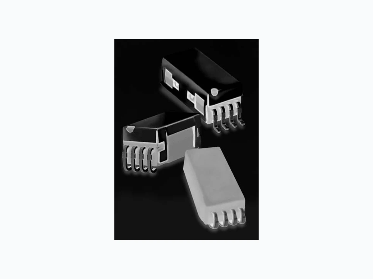
Ideally suited to the needs of Automated T est Equipment, Instrumenta- tion and T elecommunications requirements, Coto’s 9800 Series is an ultra-miniature Surface Mount Reed Relay that combines small size with exceptional RF performance. 9814 extends life at ATE loads 3X or more utilizing Coto’s proprietary switch technology. The external Magnetic Shield reduces interaction between parts in high density boards. 9852 adds a form C capability. Small size plus added features allow for high density packing, and make these relays ideal for designs such as high speed, high pin count VLSI testers where speed, size and performance are all needed. SERIES FEATURES /whwydiamond Available in Axial, Gull wing and “J” lead configurations /whwydiamond T ape and Reel packaging available /whwydiamond High reliability, hermetically sealed contacts for long life /whwydiamond High Insulation Resistance - 10 12 Ω minimum /whwydiamond Coaxial shield for 50 Ω impedance. Excellent for RF and Fast Rise Time Pulse switching (up to 6 GHz) /whwydiamond External Magnetic Shield Model 9802 Models 9814 & 9852 Axial J-Lead Gull Wing Gull Wing2 Axial J-Lead Dimensions in Inches (Millimeters)
39For Most Recent Data, Consult the Coto T echnology Website: www.cotorelay.com /c54 E-mail: info@cotorelay.com Environmental Ratings Storage T emp: -35°C to +100°C; Operating T emp: -20°C to +85°C The operate and release voltage and the coil resistance are specified at 25°C. These values vary by approximately 0.4%/°C as the ambient temperature varies. Vibration: 20 G’s to 2000 Hz; Shock: 50 G’s T op View: Dot stamped on top of relay refers to pin #1 location Notes:
1 Consult factory for life expectancy at other
switching loads. Contact resistance 2.0Ω defines end of life.
2 Surface mount component processing tempera-
ture: 438°F(226°C) max for 1 minute dwell time. T emperature measured on leads where lead exits molded package.
3 Consists of 20V Zener-diode and 1N1002 diode
in series, connected in parallel with coil. Model Number 9802 9814 9852 Parameters Test Conditions Units
1 Form A
50 Ω Coaxial 50 Ω Coaxial
1 Form C
50 Ω Coaxial COIL SPECIFICATIONS Nom. Coil Voltage VDC 5 3.3 5 3.3 5 Max. Coil Voltage VDC 6 4 6 4 6 Coil Resistance +/- 10%, 25° C Ω 150 70 150 70 110 CONTACT RATINGS Switching Voltage Max DC/Peak AC Resist. Volts 100 100 30 Switching Current Max DC/Peak AC Resist. Amps 0.25 0.25 0.1 Carry Current Max DC/Peak AC Resist. Amps 0.5 0.5 0.2 Contact Rating Max DC/Peak AC Resist. Watts 3 3 3 Life Expectancy-Typical Signal Level 1.0V,10mA x 106 Ops. 250 1000 200 N/O 100N/C Static Contact Resistance Dynamic Contact Resistance (max. init.) 0.5V, 50mA at 100 Hz, 1.5 msec Ω 0.150 0.150 0.150 RELAY SPECIFICATIONS Insulation Resistance (minimum) Between all Isolated Pins at 100V, 25°C, 40% RH Ω x 1012 1012 109 Capacitance - Typical Across Open Contacts No Shield Shield Floating Shield Guarding pF pF pF 0.2 0.2 1.0 Open Contact to Coil No Shield Shield Floating Shield Guarding pF pF pF 0.5 0.5 1.0 Closed Contact to Coil Shield Guarding pF 0.5 0.5 0.5 Contact to Shield Contacts Open, Shield Floating pF - - - Dielectric Strength (minimum) Between Contacts Contacts to Shield Contacts/Shield to Coil VDC/peak AC VDC/peak AC VDC/peak AC 200 1500 1500 200 1500 1500 200 1000 1000 Operate Time - including bounce - Typical At Nominal Coil Voltage, 30 Hz Square Wave msec. 0.25 0.25 0.26 Release Time - Typical Zener-Diode Suppression3 msec. 0.05 0.05 0.26