
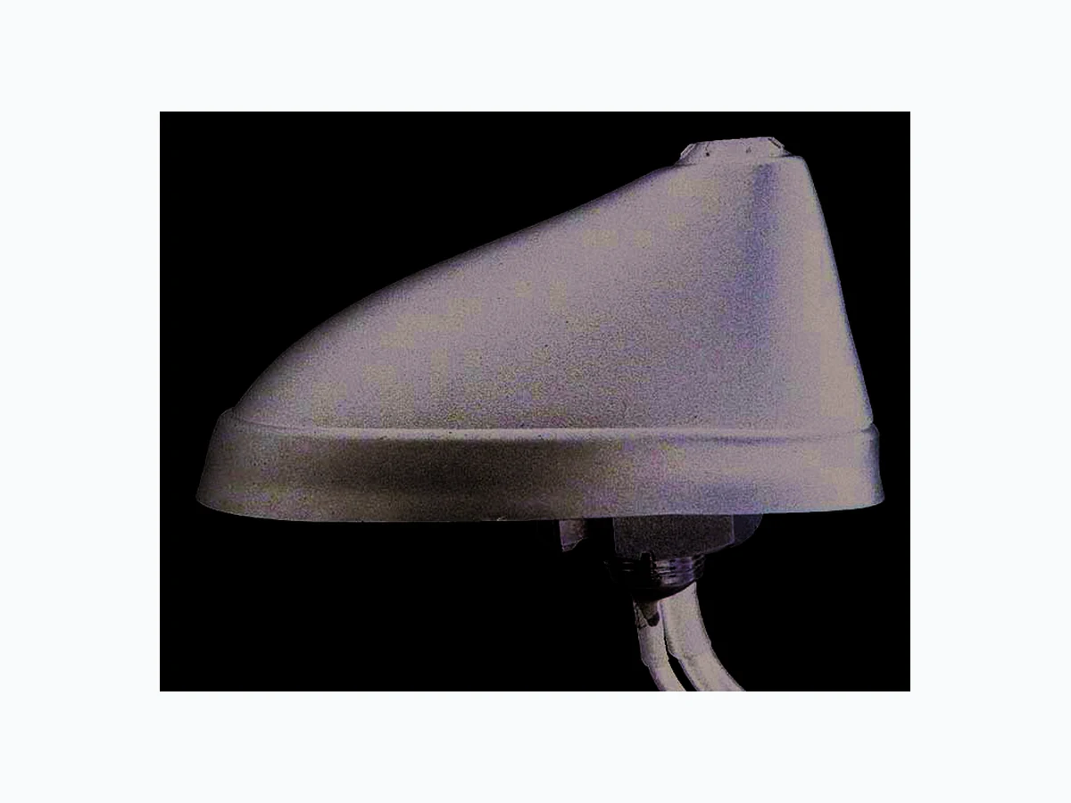
956-210-1XX TEC
Document overview
- Manufacturer or author: Provided By digicamel.com
- PDF pages: 4
Technical content
Features
- For use in telematic applications
- Requires antenna rod
- Minimum ground plane 300 x 300 mm recommended Technical Data Dimensions 95 mm x 57 mm x 42 mm Weight 260 g Temperature range -40°C – +85°C Protection class IP66 (acc. IEC 60529) Tightening torque max. 5 Nm Cable type ORBCOMM: RG 174 GPS: RG 174 Cellular: RG 58 LL, ROHS
Transportation Solutions /// ORBCOMM/ GPS/ Cellular (2G) Screw Antenna Page 2 ORBCOMM/ GPS/ Cellular (2G) Screw Antenna OGC 8521 RD S/Series | Part Number 956-210-1XX Technical Data ORBCOMM Frequency range 137 - 151 MHz Gain typ. 0 dB VSWR ≤ 2.0 Load capacity max. 10 W pulsed GPS Frequency range 1.57542 GHz ±1.023 MHz, (L1-band) Impedance 50 Ohm Gain min. 2 dBic 1) Amplification typ. 26 ±3 dB Noise figure (50 Ohm) typ. ≤ 1.4 dB Voltage supply 3 V - 5.5 V Current consumption ≤ 25mA at 5 V ±0.1 V Cellular Frequency range AMPS/GSM1900: 824-1990 MHz Gain typ. ≥ 0 dB Decoupling > 40 dB Load capacity max. 10 W pulsed 1) dBic: referenced to an isotropic radiator, circular polarization Versions PN Description ORBCOMM GPS CELL 956-210-101 OGC 8521 RD S/FAKRA/6.1 6100 mm FAKRAf, K 6050 mm FAKRAf, C 6000 mm FAKRAf, D 956-210-102 OGC 8521 RD S/FAKRA/3.1 3100 mm FAKRAf, K 3050 mm FAKRAf, C 3000 mm FAKRAf, D 956-210-103 OGC 8521 RD S/TNC/0.5 500 mm TNCm 550 mm rp-TNCf 500 mm TNCm *rp- reverse polarity Customization of cable lengths and connectors possible
Transportation Solutions /// ORBCOMM/ GPS/ Cellular (2G) Screw Antenna Page 3 ORBCOMM/ GPS/ Cellular (2G) Screw Antenna OGC 8521 RD S/Series | Part Number 956-210-1XX Installation
- Choose appropriate mounting location on flat surface (see Sketch #1)
- Ensure a minimum 300 x 300 mm ground plane
- Max. tolerable mounting material thickness 10 mm
- Safely drill 15 mm mounting hole at desired location (see Sketch #2)
- Clean mounting area with isopropyl alcohol or similar
- Unscrew mounting nut (see Sketch #3)
- Feed all cables through mounting hole
- Slide slotted mounting nut over cables and screw back on to antenna mounting stud
- Maximum tightening torque is 5 Nm Sketch #1 - Select Mounting Location Sketch #3 - Mounting NutSketch #2—Required Mounting hole Sketch #4—Mount in hole Technical Drawing
Transportation Solutions /// ORBCOMM/ GPS/ Cellular (2G) Screw Antenna Page 4 te.com/hirschmann-mobility hirschmann-mobility@te.com Hirschmann Car Communication GmbH, a TE Connectivity Company Stuttgarter Strasse 45-51
72654 Neckartenzlingen | Germany
Phone: +49 7127 14-0 | Fax: +49 7127 14-1428 TE, TE Connectivity, and TE connectivity (logo) are trademarks. Hirschmann, GSM, ORBCOMM and FAKRA are trademarks. Other products and/or company names might be trademarks of their respective owners. DISCLAIMER While TE Connectivity (TE) has made every reasonable effort to ensure the accuracy of the information in this data sheet, TE does not guarantee that it is error-free, nor does TE make any other representation, warranty or guarantee that the information is accurate, correct, reliable or current. TE reserves the right to make any adjustments to the information contained herein at any time without notice. TE expressly disclaims all implied warranties regarding the information contained herein, including, but not limited to, any implied warranties of merchantabil - ity or fitness for a particular purpose. The dimensions in this data sheet are for reference purposes only and are subject to change without notice. Specifications are subject to change without notice. Consult TE for the latest dimensions and design specifications. © 2020 TE Connectivity. All Rights Reserved. | Published 05-2020 ORBCOMM/ GPS/ Cellular (2G) Screw Antenna OGC 8521 RD S/Series | Part Number 956-210-1XX