

 Download PDF
DATASHEET SEARCH SITE
Document overview
- Manufacturer or author: Provided By digicamel.com
- PDF pages: 4
Technical content
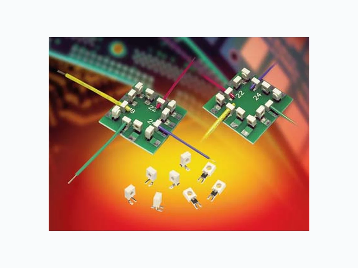
CONNECTINTERSingle Tine PTH 18-24 AWG: WTB 9176-600 ELECTRICAL Current Rating: See matrix below Voltage Rating: 600 VAC ENVIRONMENTAL Operating Temperature: -40ºC to +125ºC MECHANICAL Contact Material: Phosphor Bronze Contact Plating: Tin over Nickel Durability: 3 Cycles FEATURES AND BENEFITS IDC contact provides a gas-tight connection to the PCB for long term reliability Plastic cap retains the contact and then acts as the assembly tool to terminate the wires; no special tooling. Tested to automotive levels on shock, vibration and temperature cycling for reliability The IDC contact reduces the total applied cost versus solder or crimp processes Connectors are available in two configurations for maximum flexibility: End and Through Wire
APPLICATIONS
Machine Controls: motors, drives, solenoids, sensors, fans and pumps Commercial Buildings: controls, security, fire and sensors Smart Grid: meters, breakers and panels SSL/LED: bulbs, fixtures, signage and streetlights Application notes: reference 201-01-142 The market and applications for simple and reliable discrete Wire-to-Board (WTB) connectors continue to evolve. Developed for harsh industrial and automotive applications, Insulation Displacement Connectors (IDC) have been used in hundreds of applications connecting wires to PCB’s from transportation wiring to every day LED lighting and smart meter/sensor connections. Size, performance and simplicity have been the key factors for selecting this connector when long term reliability is critical. This single contact version of the proven 9176 family of connectors is the first in Plated Through Hole (PTH) termination. While supporting all of the features and benefits from the SMT offering, this connector provides a new option for a small, cost effective and high performance WTB solution. 9176 Series Prefix 001 Number of Ways 001 = 1 Plating Option Tin Plated HOW TO ORDER Color Option White Standard 60X Contact Style Code Description Accepted Wire Wire Gauge Gauges 600 18 AWG Stranded ø1.6-2.1 601 20 AWG Solid and Stranded ø1.6-2.1 602 22 AWG Solid and Stranded ø1.1-1.6 603 24 AWG Solid and Stranded ø1.1-1.6 CURRENT RATING 18AWG 20AWG 22AWG 24AWG 9A 8A 6A 5A Capped IDC Connector PTH PCB Mount X Cap Options Code Cap Option Description Details
0 Through Wire Allows wire to be See
terminated at any point page 2 Terminates end of wire See9 Wire Stop End protected by page 3stop face
CONNECTINTERSingle Tine PTH 18-24 AWG: WTB 9176-600 18-24 AWG 1 WAY PTH CONNECTOR THROUGH WIRE CAPPED SUGGESTED PCB LAYOUT NOTES: 1. 1 WAY CONNECTOR FOR PTH WIRE TO BOARD CONNECTION, PRE-ASSEMBLED THROUGH WIRE CAP , CODE SEE PAGE 1. 2. CONTACT/CAP TO MATCH 20AWG-24AWG SOLID AND STRANDED WIRES, 18AWG WILL ONLY ACCEPT STRANDED WIRES, SEE TABLE. 3. FLAT FACE ON TOP OF CAP TO AID PICK AND PLACE ASSEMBLY, MAXIMUM DIAMETER 1.8MM. 4. FOR FULL PRODUCT SPECIFICATION ON STANDARD CONNECTORS REFER TO ELCO SPEC 201-01-163. 5. ASSEMBLY PROCEDURE, REFER TO APPLICATION NOTES 201-01-142. 6. GENERAL TOLERANCE ±0.20 UNLESS STATED. 7. PACKED IN TAPE AND REEL, QUANTITY PER REEL 500. 8. CONNECTOR OUTLINE. 9. CONTACT MATERIAL: TIN PLATED COPPER ALLOY. 10. INSULATION MATERIAL: HIGH TEMPERATURE NYLON, GLASS FILLED, UL94 V-O. COLOR REFER TO PAGE 1. PACKING DETAILS Code Accepted A Wire BWire Gauge Insulation 600 18 AWG Stranded 0.74 Ø 1.6-2.1 2.1 601 20 AWG Solid or Stranded 0.60 Ø 1.6-2.1 2.1 602 22 AWG Solid or Stranded 0.47 Ø 1.1-1.6 1.6 603 24 AWG Solid or Stranded 0.37 Ø 1.1-1.6 1.6
CONNECTINTERSingle Tine PTH 18-24 AWG: WTB 9176-600 18-24 AWG 1 WAY PTH CONNECTOR WIRE STOP CAPPED SUGGESTED PCB LAYOUT NOTES: 1. 1 WAY CONNECTOR FOR PTH WIRE TO BOARD CONNECTION, PRE-ASSEMBLED WIRE STOP CAP , CODE SEE PAGE 1. 2. CONTACT/CAP TO MATCH 20AWG-24AWG SOLID AND STRANDED WIRES, 18AWG WILL ONLY ACCEPT STRANDED WIRES, SEE TABLE. 3. FLAT FACE ON TOP OF CAP TO AID PICK AND PLACE ASSEMBLY, MAXIMUM DIAMETER 1.8MM. 4. FOR FULL PRODUCT SPECIFICATION ON STANDARD CONNECTORS REFER TO ELCO SPEC 201-01-163. 5. ASSEMBLY PROCEDURE, REFER TO APPLICATION NOTES 201-01-142. 6. GENERAL TOLERANCE ±0.20 UNLESS STATED. 7. PACKED IN TAPE AND REEL, QUANTITY PER REEL 500. 8. CONNECTOR OUTLINE. 9. CONTACT MATERIAL: TIN PLATED COPPER ALLOY. 10. INSULATION MATERIAL: HIGH TEMPERATURE NYLON, GLASS FILLED, UL94 V-O. COLOR REFER TO PAGE 1. 11. WIRE STOP CAP PROTECTS END OF WIRE. PACKING DETAILS Code Accepted A Wire BWire Gauge Insulation 600 18 AWG Stranded 0.74 Ø 1.6-2.1 2.1 601 20 AWG Solid or Stranded 0.60 Ø 1.6-2.1 2.1 602 22 AWG Solid or Stranded 0.47 Ø 1.1-1.6 1.6 603 24 AWG Solid or Stranded 0.37 Ø 1.1-1.6 1.6
CONNECTINTERSingle Tine PTH 18-24 AWG: WTB 9176-600 18-24 AWG ASSEMBLED CAPPE PTH CONNECTORS NOMINAL ASSEMBLED HEIGHTS TYPICAL THROUGH WIRE ASSEMBLIES TYPICAL WIRE STOP ASSEMBLIES