
9171 ETC2
Document overview
- Manufacturer or author: Provided By www.digicamel.com(FREE DATASHEET DOWNLOAD SITE)
- PDF pages: 6
Technical content
Program m able D ual-Range D C Pow er Supplies 9170 & 9180 series D ata Sheet w w w .bkprecision.com Technical data subject to change © B& K Precision Corp. 2014 The 9170/9180 series program m able D C power supplies offer industry leading perform ance, designed to m eet the m ost dem anding applications in R& D , design verification, and production test. A ll nine m odels deliver clean, stable and precise output power due to their exceptionally low ripple and noise, low tem perature coefficient, excellent regulation, and fast transient response tim e characteristics. These power supplies are well suited for both bench use and A TE applications. For bench use, these power supplies offer an intuitive user interface with a full num erical keypad for convenient data entry. R& D and design engineers will appreciate front panel output and rem ote sense term inals (available on select m odels) . Free application software is provided for rem ote control without the need for any com puter program m ing. U SB and optional G PIB/LA N interfaces com bined with a fast transient response tim e, m ake this series ideal for A TE applications. A dditionally, this series offers unique features not typically found in other power sources on the m arket, such as versatile LED test m odes, Features & Benefits I Single and dual output m odels with up to 2 10W output power I D ual range output with autom atic range selection* I Program m able voltage and current slew rates I Front and rear panel output term inals for convenient wiring I Rear panel rem ote sense term inal (additional front panel rem ote sense term inal on select single channel m odels*) I List m ode for executing up to 10 stored test sequences with a m axim um of 15 0 steps in total I Store and recall up to 10 power settings I SCPI com pliant U SB standard interface, RS2 3 2 , G PIB & LA N , RS485 optional (Installation through m odular interface slots) I Rem ote analog program m ing interface (option) I U nique LED test m odes for m inim izing inrush current I A pplication software for rem ote control I O vervoltage (O VP) and overcurrent (O CP) protection, including key-lock function I Convenient voltage and current calibration via front panel I LabVIEW TM drivers available for download O utstanding perform ance com bined w ith unique features * Except for high voltage m odels 9184 and 9185 . O utput Rating N o. of O utputs M odel 0-10 V , 0-10 A / 0-2 0 V , 0-5 A 1 9171 0-3 5 V , 0-3 A / 0-70 V , 0-1.5 A 1 9172 0-10 V , 0-10 A / 0-2 0 V , 0-5 A 2 9173 0-3 5 V , 0-3 A / 0-70 V , 0-1.5 A 2 9174 0-18 V , 0-8 A / 0-3 6 V , 0-4 A 1 9181 0-10 V , 0-2 0 A / 0-2 0 V , 0-10 A 1 9182 0-3 5 V , 0-6 A / 0-70 V , 0-3 A 1 9183 0-100 V , 0-2 A / 0-2 00 V , 0-1 A 1 9184 0-400 V , 0-0.5 A / 0-600 V , 0-0.3 5 A 1 9185 m odular interface card slots, autom atic range selection, and an optional 8-bit bidirectional digital I/O interface. T o protect your D U T (device under test), the 9170/9180 series provides safety options such as O VP , O CP , and a key-lock feature to prevent accidental change of param eters that m ight dam age your D U T . Built for reliability, the supplies are also backed by a 3 year warranty.
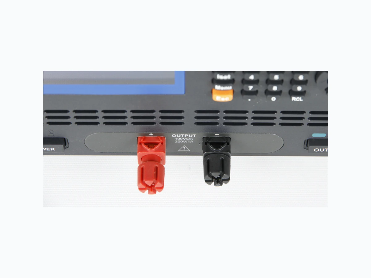
w w w .bkprecision.com Program m able D ual-Range D C Pow er Supplies 9170 & 9180 series Bright display showing both m easured output value and set value Vertical and horizantal cursors m ake studying U U T response to sm all voltage or current changes easy D irect-entry num eric keypad to set precise voltage and current values Front panel rem ote sense term inal (all single channel m odels except 9184 and 9185 ) H igh voltage m odels com e with special binding posts engineered for m axim um safety Individual output on/off buttons for each output channel D edicated indicators for im portant safety functions Front panel Rear panel Standard U SB interface Intelligent tem perature-controlled, low noise cooling fan Rear panel output and rem ote sense term inals M o d ular interface card slo ts O nly buy what you need, when you need it. Pick and choose from up to 4 different types of interface cards to install at tim e of purchase or upgrade later. Interface card options include: LA N and G PIB, D igital I/O and A nalog Control, RS485 , or RS2 3 2 . Installation is quick and easy and does not require opening the instrum ent case (does not void warranty). D ual channel m odels H igh voltage m odels
w w w .bkprecision.com Program m able D ual-Range D C Pow er Supplies 9170 & 9180 series External control and program m ing Versatile connectivity These power supplies offer SCPI IEEE488.2 com patible standard U SB, optional G PIB and LA N interfaces, and an optional 8-bit digital I/O and analog control card to facilitate test system developm ent and integration. A pplication softw are Create test sequences for execution in list m ode via the G PIB or U SB interface using the included PC software. I Create, save, and load program lists I View output characteristic curves and export data to a file I Pass/Fail test m onitors m axim um and m inim um voltage and current values over a specified period of tim e Test sequence execution in list m ode The list m ode feature allows users to download a list of com m ands to the power supply’s internal m em ory and execute them . A total of 15 0 steps can be allocated to one of 10 internal m em ory locations. The test sequence can be program m ed rem otely through the included application software or via the U SB, G PIB, or LA N interfaces using SCPI com m ands. Each step’s voltage, current, and duration param eters can be set, with sequences configured for single or repeated execution. Telnet interface (2) Power supplies can be controlled with SCPI com m ands via a T elnet connection over the Ethernet interface. A ny com puter with a T elnet client can be used to control the power supply. W eb server interface (2) The 9170/9180 series power supplies with the G PIB/LA N interface installed provide a built-in W eb server that allows users to configure, control, or m onitor the basic settings of the power supply from a rem ote com puter using a Java- enabled W eb browser. Connect to the user-defined IP address to view the web control page. SCPI com m ands can also be sent through the W eb server interface. Interface for controlling voltage, current, and output state Control settings page for configuration of protection and password settings for the system External analog program m ing interface (1 ) The power supplies’ output voltage and current can be controlled by either external analog voltage or resistance. U se a 0-5 V or 0-10 V external D C voltage source, or 0-5 k Ω variable resistor to control the output from zero to full scale. M ulti-unit control (3 ) In m ulti-unit control m ode, up to 3 1 units can be daisy chained via the RS485 interface for synchronization purposes and controlled from one m aster unit via the U SB, G PIB, or LA N interface. (1) Requires card option D R1D IO or D R2 D IO (2 ) Requires card option D RG L (3 ) Requires card option D RRS485
w w w .bkprecision.com Program m able D ual-Range D C Pow er Supplies 9170 & 9180 series * Low current m ode for high voltage m odels 9184 and 9185 only. LED m ode W ith LED m ode active, inrush current will be elim inated or m inim ized to protect the U U T . Low current m ode* This unique function enables the power supply to m inim ize the voltage rise tim e in a controlled m anner. This m ode is used when operating at a low current (< 1 A ) and quick transitions from a high-to-low or low-to-high voltage are needed. T o address the growing LED m arket, the 9170/9180 series design incorporates special LED test m odes for efficient and safe electrical tests of LED panels. Powering LED s with conventional power supplies will potentially cause perm anent dam age to the U U T or lim it its lifespan due to excessive inrush current at power up and the non-linear characteristics of the LED ’s I-V curve. These power supplies feature two distinct operating m odes suitable for LED testing in a m anufacturing or R& D environm ent and other special applications requiring a controlled rise tim e at power up without generating any inrush current. Exam ple LED test setup Low current m ode O FF Low current m ode O N Current flow during power up with LED m ode enabled 9170/9180 Series O perating Range Voltage rise tim e with and without low current m ode enabled Inrush current O utput O N 20 m s 5 m s O utput O N Test m odes for LED and other special applications LED m ode O FF LED m ode O N The 9170/9180 series provide a unique dual range feature that offers the best of both worlds by supplying two different ranges. U sers can select between high and low range operation for either m ore voltage or m ore current depending on your application, avoiding the higher cost of buying m ore power than necessary. Tw o pow er supplies in one
w w w .bkprecision.com Program m able D ual-Range D C Pow er Supplies 9170 & 9180 series Specifications 91 71 91 72 91 73 91 74 91 81 91 82 91 83 91 84 91 85 O utput Rating Low Range 0-10 V , 0-10 A 0-3 5 V , 0-3 A 0-10 V , 0-10 A 0-3 5 V , 0-3 A 0-18 V , 0-8 A 0-10 V , 0-2 0 A 0-3 5 V , 0-6 A 0-100 V , 0-2 A 0-400 V , 0-0.5 A H igh Range 0-2 0 V , 0-5 A 0-70 V , 0-1.5 A 0-2 0 V , 0-5 A 0-70 V , 0-1.5 A 0-3 6 V , 0-4 A 0-2 0 V , 0-10 A 0-70 V , 0-3 A 0-2 00 V , 0-1 A 0-600 V , 0-0.3 5 A N um ber of Channels 1 1 2 2 1 1 1 1 1 M ax O utput Power 100 W 105 W 2 00 W 2 10 W 144 W 2 00 W 2 10 W 2 00 W 2 10 W Line Regulation Voltage ≤ 0.01 % + 1 m V Current ≤ 0.01 % + 2 5 0 uA Load Regulation 1 Voltage ≤ 0.01 % + 1 m V Current ≤ 0.01 % + 2 5 0 uA Ripple and N oise (2 0 H z – 2 0 M H z) N orm al M ode Voltage ≤ 0.3 5 m Vrm s / ≤ 3 m Vpp ≤ 0.5 m Vrm s / ≤ 5 m Vpp ≤ 0.3 5 m Vrm s / ≤ 3 m Vpp ≤ 0.5 m Vrm s / ≤ 5 m Vpp ≤ 0.3 5 m Vrm s / ≤ 3 m Vpp ≤ 0.5 m Vrm s /≤5 m Vpp ≤ 1.5 m Vrm s / ≤ 15 m Vpp ≤ 4.5 m Vrm s / ≤ 45 m Vpp N orm al M ode Current ≤ 2 m A rm s Com m on M ode Current ≤ 1.5 uA rm s Program m ing / Readback Resolution Voltage 1 m V 2 m V 1 m V 2 m V 1 m V 2 m V 10 m V 2 0 m V Program m ing / Readback A ccuracy ± (% output+ offset) Voltage ≤ 0.05 % + 5 m V ≤ 0.05 % + 10 m V ≤ 0.05 % + 5 m V ≤ 0.05 % + 10 m V ≤ 0.05 % + 5 m V ≤ 0.05 % + 10 m V ≤ 0.05 % + 5 0 m V ≤ 0.05 % + 100 m V Current ≤ 0.1 % + 2 m A ≤ 0.1 % + 1 m A ≤ 0.1 % + 2 m A ≤ 0.1 % + 1 m A ≤ 0.1 % + 2 m A ≤ 0.1 % + 5 m A ≤ 0.1 % + 2 m A ≤ 0.1 % + 1 m A ≤ 0.1 % + 0.1 m A T em perature Coefficient per °C ± (% output+ offset) Voltage ≤ 0.005 % + 1 m V ≤ 0.005 % + 10 m V ≤ 0.005 % + 2 0 m V Current ≤ 0.01 % + 3 m A Transient Response Tim e 2 ≤ 5 0 µs for output to recover to within 15 m V ≤ 100 µs for output to recover to within 5 0 m V ≤ 100 µs for output to recover to within 12 0 m V Settling Tim e 3 ≤ 3 0 m s M easurem ent Tim e ≤ 5 0 m s O VP A ccuracy ≤ 0.5 % + 0.1 V ≤ 0.5 % + 1 V O CP A ccuracy ≤ 0.5 % + 0.1 A O VP/O CP Response Tim e 4 ≤ 1 m s Rising Tim e at Full Load / N o Load ≤ 8 m s ≤ 10 m s ≤ 8 m s ≤ 10 m s ≤ 8 m s ≤ 10 m s ≤ 3 0 m s ≤ 40 m s Falling Tim e at Full Load ≤ 8 m s ≤ 10 m s ≤ 8 m s ≤ 10 m s ≤ 8 m s ≤ 10 m s ≤ 3 0 m s ≤ 40 m s Falling Tim e at N o Load ≤ 2 5 0 m s Stability (8 hrs) ± (% output+ offset) Voltage ≤ 0.02 % + 2 m V ≤ 0.02 % + 10 m V ≤ 0.02 % + 2 0 m V Current 0.1 % + 1 m A N otes: 1 W ith sense term inal connected. 2 Following a change in output current from full load to half load or vice versa. 3 M axim um tim e required for the output voltage to change from 1% to 99% or vice versa after receiving a VO LTage or VSET com m and via G PIB or U SB interface. 4 A verage tim e for output to start to drop after O VP/O CP condition occurs.
v080414 6 w w w .bkprecision.com Program m able D ual-Range D C Pow er Supplies 9170 & 9180 series Specifications (cont.) 91 71 91 72 91 73 91 74 91 81 91 82 91 83 91 84 91 85 Supplem ental Characteristics D im ensions (W x H x D ) (2 10 x 87 x 415 m m ) (2 10 x 13 0.5 x 415 m m ) (2 10 x 87 x 415 m m ) (2 10 x 13 0.5 x 415 m m ) Rack M ount H eight 2 U 3 U 2 U 3 U W eight 17 lbs (7.7 kg) 2 3 .1 lbs (10.5 kg) 17 lbs (7.7 kg) 2 6.4 lbs (12 kg) 2 4.2 lbs (11 kg) 2 3 .lbs (10.5 kg) Safety EN 61010-1:2 001, EU Low Voltage D irective 2 006/95 /EC Electrom agnetic Com patibility M eets EM C D irective 2 004/108/EC, EN 613 2 6-1:2 006 Standard Interface U SB A C Input 115 /2 3 0 VA C ± 10% , 47 H z - 63 H z Environm ental O perating T em perature 0 °C - 40 °C, < 75 % R.H . Storage T em perature -10 °C - 70 °C, < 85 % R.H . Three-Year W arranty A ccessories Included U ser m anual, A C power cord, U SB cable (type A to type B), line fuse, certificate of calibration and test report N ote: A ll specifications apply to the unit after a tem perature stabilization tim e of 15 m inutes over an am bient tem perature range of 2 3 °C ± 5 °C. O rder inform ation for instrum ent options Interface cards D escription D RG L G PIB/LA N card D R1D IO Single channel digital I/O and analog control card D R2 D IO D ual channel digital I/O and analog control card D RRS485 RS485 interface card D RRS2 3 2 RS2 3 2 interface card Single channel m odels: 9171, 9172 , 9181, 9182 , 9183 , 9184, 9185 D ual channel m odels: 9173 , 9174 Rackm ount kits D escription D RRM 2 U 1 Rackm ount kit for one 2 U instrum ent D RRM 2 U 2 Rackm ount kit for two 2 U instrum ents m ounted side by side D RRM 3 U 1 Rackm ount kit for one 3 U instrum ent D RRM 3 U 2 Rackm ount kit for two 3 U instrum ents m ounted side by side
2 U size m odels: 9171, 9172 , 9181
3 U size m odels: 9173 , 9174, 9182 , 9183 , 9184, 9185
N ote: A ll options can be installed by the user and purchased at any tim e, either together with the instrum ent or after. LA N /G PIB card RS485 card RS2 3 2 card Single and dual channel digital I/O analog input control cards Interface Card O ptions