

 Download PDF
INTERFACEUNITS WEIDMULLER
Document overview
- PDF pages: 17
Technical content
Page 1
Contents
Interface Units
Interface Units
Introduction
A.2 A
Interface Units IEC 603-1 – DIN 41651 (Ribbon Connector)
A.6
Interface Units IEC 807-2 – DIN 41652 (Sub-D Connector)
A.9
Supply Voltage Distributor Modules
A.13
Interface Units with RJ45 Plug Connectors
A.15
ELCO Interface Unit
A.16
T-CON Interface Unit
A.17
A.1
Page 2
Introduction
Weidmuller interface units
Given the need to reduce costs in electrical cabinet construction, A interface units offer an alternative to wiring concepts with point-to-point wiring. The prime function of interface units is to act as a trouble-free adapter element between standardized plug connectors and point-to-point wiring or other connection systems.
Interface units consist of the following individual components:
- Extruded profile for inserting the PCB
- End plates for fitting on the mounting rail
- Clip-on feet for locking on standardized mounting rails TS 32 and TS 35
- PCB with connecting and indicating elements, DIN plug connectors and ample marking facilities for equipment identification
The plug connectors used for the interface units can be divided into the following groups:
- Plug connector to IEC 603-1/DIN 41651
- Sub-miniature plug connectors (SUB-D) to IEC 807-2/ DIN 41652
- Plug connectors for PCBs to IEC 603/DIN 41612 and DIN 41615
- ELCO plug connectors for hazardous area applications
Advantages of the interface units:
- Two- and three-tier PCB terminals save space
- Conventional point-to-point wiring only needed on one side, thus saving costs
- Greater safety, preventing wiring errors
- Optional: status LED on the interface units
- Rapid troubleshooting with additional test and measuring devices
- Simplified setup and documentation
Interface units let users implement pioneering concepts in switchboard design with potential for rationalization. Customized wiring concepts can also be solved rationally through the use of special interface units.
A.2
Pre-assembled leads with the corresponding plug connector systems are used as the connection between the seriesconnected controller and the interface unit. This provides the greatest savings for the user. The use of interface units reduces the individual circuitry, which reduces labor and installation time and also hidden costs, in particular a reduction material costs following a reduction in the number of individual cables and leads, cable ducts, terminals and terminal blocks required. The transition to point-to-point wiring takes place directly at the interface element.
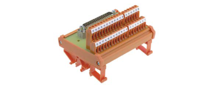
Users have a choice between screw, tension clamp or spade connections for connecting actuators and/or sensors. As an option, interface units can also integrate additional functions such as status indicator, signal disconnector, fuses or shielding. Identification systems make it easier to trace the signals to the corresponding element.
RSF interface units for pre-assembled leads with plug connectors to IEC 603-1/DIN 41651
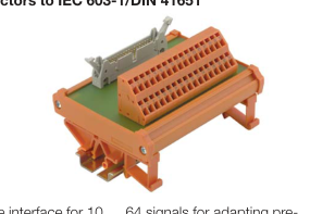
Passive interface for 10 … 64 signals for adapting preassembled leads with plug connectors to IEC 603-1 / DIN 41651 to screw or tension clamp connection systems.
When used in combination with a status indicator (LED), this guarantees rapid information about the switching state of incoming and outgoing signals.
Page 3
RSSD interface units for pre-assembled leads with SUB-D plug connectors to IEC 807-2/DIN 41652
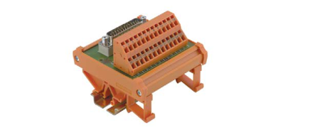
Passive interface unit for 9 … 50 signals for adapting preassembled leads with SUB-D plug to IEC 807-2/DIN 41652 to screw or tension clamp connection systems.
The components are supplied with either female or male connectors. A spacer block between plug connector and PCB cushions the mechanical forces occurring between the connected cables. RSSD interface units can be supplied with an ground terminal for shielded leads as an optional feature. An additional test point simplifies testing and measuring during initial setup and when servicing the system.
RS VERT interface units as voltage distributor
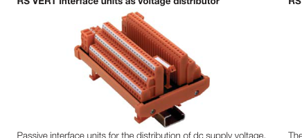
These interface units are available in three designs for distribution to 8, 16 and 72 connections, for positive and negative voltages in each case:
- 8x and 16x distributor just 45 mm wide overall, 72x distributor 100 mm wide
- Fed by two connection elements for positive and negative voltages in each case
- Fits on TS32/35 mounting rails
RS VERT voltage distributors can also be used in small enclosures and provide clearly organized distribution.
Introduction
RS ELCO interface units for pre-assembled leads with
A
hermaphrodite plug connector system
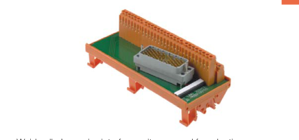
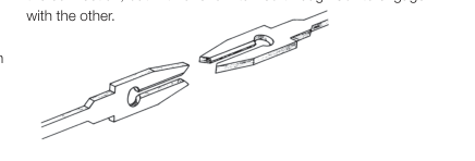
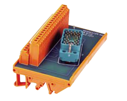
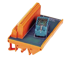
Weidmuller’s passive interface units are used for adapting hermaphrodite ELCO multi-pole connectors, for input and output, to screw terminal systems. The hermaphrodite contact is a fork-type contact that is identical in design on both sides of the connection, but with one fork turned through 90° to engage
RS RJ45 interface units for connecting data lines
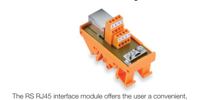
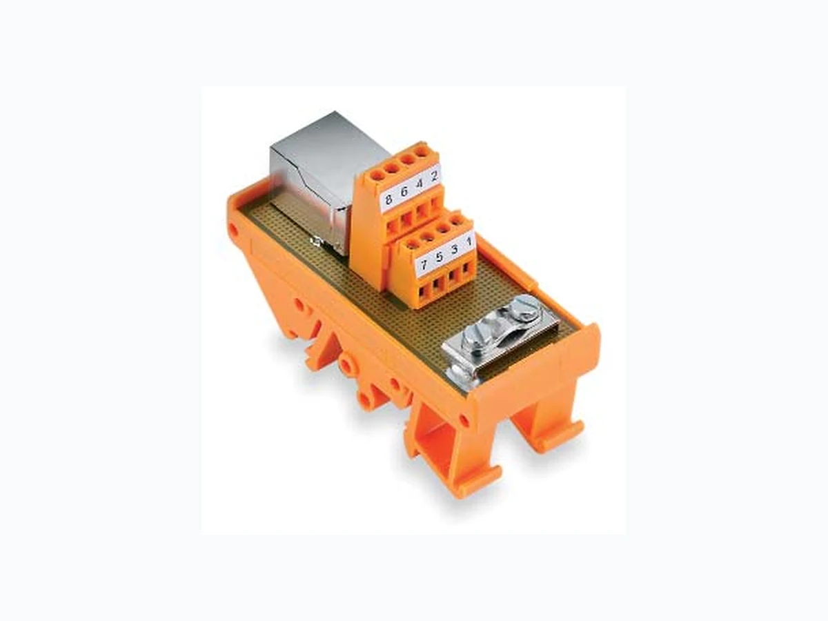
easy-to-use interface for connecting modems, notebooks and other office equipment in the electrical cabinet.
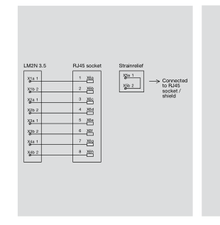
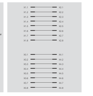
The module converts the standard RJ45 connection to a screw terminal system or acts as a coupling to connect data leads by means of two RJ45 sockets. For data transmission rates of up to 100 Mbps, it is advisable to connect one end of the shield of the data cable to a protective ground. The interface modules can be fitted on TS 32/35 mounting rails.
A.3
Page 4
Introduction
Weidmuller Custom Solutions
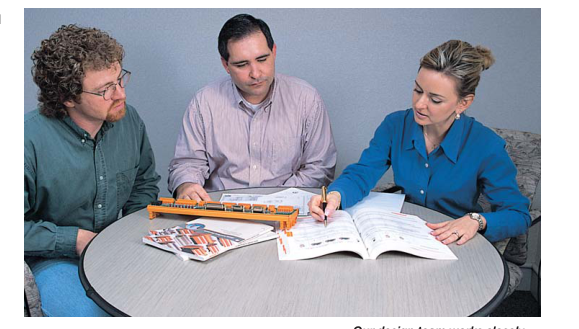
It’s a Matter of Getting what you need
A Custom Design and Engineering – Designed for Your Application Great ideas for new products and new applications often push companies into uncharted territory, where existing interface products fall short of their design requirements.
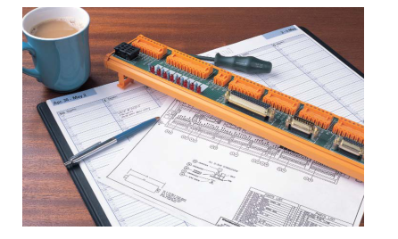
Weidmuller has an unparalleled record of innovation in interface products extending back over 50 years – and we’re happy to make this expertise available to you through our custom engineering services, which include both the design and the manufacture of tailor-made interface products. Whether it’s PCB terminal blocks and connectors, DIN-rail terminal blocks, controller front panel adapters or controller interface products, we will work with you to create a custom solution that meets your needs – exactly.
Our goal is to provide you with the most responsive service possible.
A.4
Our design team works closely with you each step of the way.
And because our success at Weidmuller rests on long-term relationships, we welcome opportunities to partner with you to create the products you need.
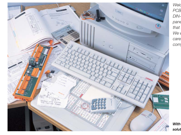
Weidmuller is your best source for PCB terminal blocks and connectors, DIN-rail terminal blocks, controller front panel adapters and interface products that meet your application needs precisely. We work with you to manage the process carefully to ensure timely delivery and complete satisfaction.
With Weidmuller’s expertise in custom solutions, there is no need to compromise.
Page 5
Final design drawings are developed for review and approval.
4) Developing Final Drawings
1) Getting it Right from the Start
and Models
Once an application is identified, we
At Weidmuller, we want to make
mobilize our design team immediately. We work with you to pinpoint your design absolutely sure that a custom product
design meets your requirements.
specifications, delivery and scheduling
Using the latest CAD technology,
requirements.
we create final design drawings
As part of this effort, we establish an open
and stereolithographic models, as
line of communication between you and
appropriate.
a designated point person for your project. Expert technical support is also available all the way through the project to address issues that arise during the design and
Introduction
A
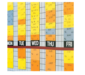
We work with you to pinpoint schedule and delivery requirements.
5) Establishing Time Frames Upon your approval, we begin the tooling process, schedule production, and set delivery dates based on the needs of your application. Our Fastrack Custom Solutions can accelerate the custom design and engineering process even further. In many cases, we will produce conceptual drawings for you within two days of project agreement.

manufacturing process.
2) Building Relationships Before Building the Product At Weidmuller, we place a premium on building long-term customer relationships. We will explain our custom design and en- gineering process in detail, and, as needed, partner with you to meet your needs for custom products.
3) Offering Alternatives One of the advantages of working with Weidmuller is the depth of our product design and manufacturing experience. You can count on us to carefully review the special requirements for your applica - tion and, if necessary, present several approaches and to compare the advantages of each one.
A.5
Page 6
Interface Units IEC 603-1 - DIN 41651 (Ribbon Connector)
Interface units IEC 603-1
RSF S 45 mm/ IEC 603-1
RSF Z/ IEC 603-1
DIN 41651 (Ribbon connector)
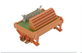
- Pin connector with locking feature to IEC 603-1
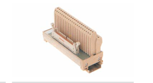
- Tension clamp or screw connection system
- 45 or 87 mm wide
- For mounting on TS32, TS35 x 7.5 and TS35 x 15
A
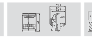

Technical data
Connection data
Connection data
Connection on process side
PCB terminal LM2NZF / Tension clamp
Stripping length
7.0 mm ing length
Connection on control side 03-1/ DIN 41651
Plug-in connector to IEC 603-1/ DIN 41651
Rated data
Rated data
Conversion PCB/plug connector
1:1 ersion PCB/plug connector
Rated voltage DC
60 V AC/ 75 V DC
Rated current per connection
1 A ed current per connection
Test voltage (~eff)
1.0 kV oltage (~eff)
Test torque
Test torque
Storage temperature
-40 °C…+70 °C ure
Ambient temperature (operational)
0 °C…+55 °C ature (operational)
Terminal rail
Terminal rail
Insulation coordination (EN 50178)
Insulation coordination (EN 50178)
Surge category
III e category
Pollution severity
2 llution severity
Approvals
Approvals
Standards
EN 50178
Clamping range (rating- / min. / max.)
mm2 1.5 / 0.5 / 2.5
Length x width x height
mm 87.0 x — x 64.0
Note
Ordering data
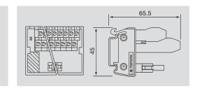
Connection data PCB terminal LPK 2 H / Screw connection 7.0 mm ing length Plug-in connector to IEC 603-1/ DIN 41651
Rated data 1:1 ersion PCB/plug connector 60 V AC/ 75 V DC 1 A ed current per connection 1.0 kV oltage (~eff) 0.40 Nm rque -40 °C…+70 °C ure 0 °C…+55 °C ature (operational) TS 35 al rail
Insulation coordination (EN 50178) III e category 2 llution severity Approvals EN 50178
1.5 / 0.5 / 2.5 45.0 x — x 65.5
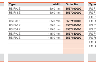
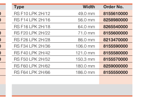
10-pole 14-pole 16-pole 20-pole 26-pole 34-pole 40-pole 50-pole 60-pole 64-pole
Note
Accessories
Note
A.6
Page 7
Interface Units IEC 603-1 - DIN 41651 (Ribbon Connector)
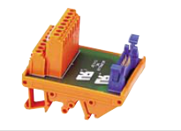
RI-IDC
For ribbon cable connections
according to UL 508A recognition
Cable interface units for ribbon cables
or with accessory holes
Screw connection Male Standard
- With mounting foot for TS 32, TS 35 x 7.5
and TS 35 x 15 rails
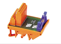
- Male connector block with interlock for
female connector block with strain relief according to DIN 41 651/Parts 1 and 2
- Available with screw connection
RI-IDC
Cable interface units for ribbon cables Screw connection Male with accessory holes
A

Technical data
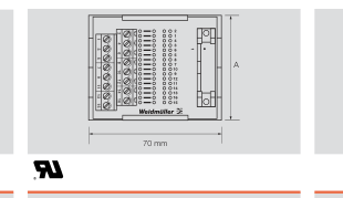
Connection data - Process side
Screw connection
- Type
LP2N terminal
- Control side
Plug connection
- Type
Ribbon connector
Rated data Rated voltage
125 V
Rated current per contact
1 A
Operating temperature
-25°C…+50°C
Storage temperature
-40°C…+70°C
Terminal wire size
AWG 26…12
Insulation stripping length
mm (in.) 7 (.28)
Dimensions Overall width
mm (in.) See table, dim. A
Ordering data
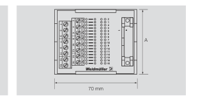
Screw connection LP2N terminal Plug connection Ribbon connector
125 V 1 A -25°C…+50°C -40°C…+70°C
AWG 26…12 7 (.28)
See table, dim. A
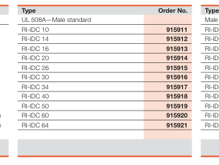
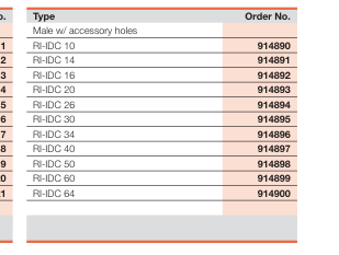
dimensions (mm/in.) Poles Dim. A
Dim. B Dim. C Dim. D
10 39.88 (1.57) 50 (1.97)
49 (1.93) 40 (1.57)
14 49.78 (1.96) 50 (1.97)
56 (2.20) 45 (1.77)
16 55.12 (2.17) 55 (2.17)
64 (2.52) 50 (1.97)
20 64.77 (2.55) 65 (2.56)
71 (2.80) 50 (1.97)
26 84.84 (3.34) 80 (3.15)
86 (3.39) 55 (2.17)
30 94.74 (3.73) 34 104.65 (4.12) 110 (4.33) 106 (4.17) 70 (2.76) 40 120.14 (4.73) 115 (4.53) 121 (4.76) 80 (3.15) 50 142.49 (5.60) 145 (5.71) 151 (5.94) 95 (3.74) 60 175.01 (6.89) 180 (7.09) 180 (7.09) 115 (4.53) 64 181.61 (7.15) 180 (7.09) 186 (7.32) 120 (4.72) On TS 35 x 7.5
Accessories
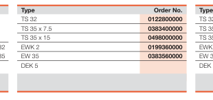
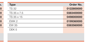
Mounting rail
End bracket
for TS 32 for TS 35
Terminal wire marking
A.7
Page 8
Interface Units IEC 603-1 - DIN 41651 (Ribbon Connector)
Interface units IEC 603-1
RSF S/ IEC 603-1
RSF S/ IEC 603 -1
DIN 41651 (Ribbon connector)
- Pin connector with locking feature to IEC 603-1
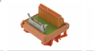
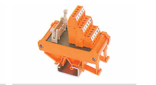
- Screw connection system
- 87 mm wide
- For mounting on TS32, TS35 x 7.5 and TS35 x 15
A
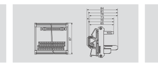

Technical data
Connection data
Connection data
Connection on process side
PCB terminal LP2N ess side
Stripping length
7.0 mm ing length
Connection on control side 03-1/ DIN 41651
Plug-in connector to IEC 603-1/ DIN 41651
Rated data
Rated data
Conversion PCB/plug connector
1:1 ersion PCB/plug connector
Rated voltage DC
60 V AC/ 75 V DC
Rated current per connection
1 A ed current per connection
Test voltage (~eff)
1.0 kV oltage (~eff)
Test torque
0.50 Nm rque
Storage temperature
-40 °C…+60 °C ure
Ambient temperature (operational)
0 °C…+55 °C ature (operational)
Terminal rail
TS 32, TS 35
Insulation coordination (EN 50178)
Insulation coordination (EN 50178)
Surge category
III e category
Pollution severity
2 llution severity
Approvals
Approvals
Standards
EN 50178
Clamping range (rating- / min. / max.)
mm2 2.5 / 0.5 / 4
Length x width x height
mm 87.0 x — x 70.0
Note
Ordering data
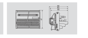
Connection data PCB terminal LP3R ess side 7.0 mm ing length Plug-in connector to IEC 603-1/ DIN 41651
Rated data 1:1 ersion PCB/plug connector 60 V AC/ 75 V DC 1 A ed current per connection 1.0 kV oltage (~eff) 0.50 Nm rque -40 °C…+70 °C ure 0 °C…+55 °C ature (operational) TS 32, TS 35
Insulation coordination (EN 50178) III e category 2 llution severity Approvals EN 50178
2.5 / 0.5 / 4 87.0 x — x 76.0
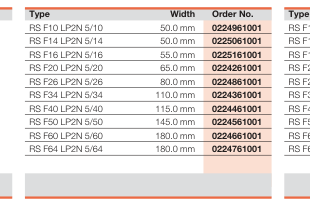
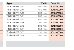
10-pole 14-pole 16-pole 20-pole 26-pole 34-pole 40-pole 50-pole 60-pole 64-pole
Note
Accessories
Note
A.8
Page 9
Interface Units IEC 807-2 - DIN 41652 (Sub-D Connector)
RD
RD
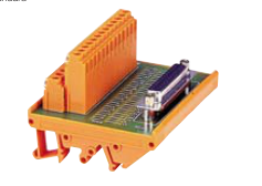
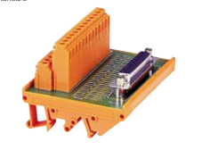
For D-subminiature plug-in
connectors according to
Male connector
Female connector
UL 508A recognition
Standard
Standard
- With mounting foot for TS 32,
TS 35 x 7.5 and TS 35 x 15 rails
- Male and female connectors with
screw/locking system UNC 4/40
- Available with screw connection
A

Technical data
Connection data - Process side
Screw connection
- Type
LP2N terminal
- Control side
Plug connection
- Type
Sub-D
Rated data Rated voltage
150 V
Rated current per contact
1.5 A
Operating temperature
-25°C…+50°C
Storage temperature
-40°C…+70°C
Terminal wire size
AWG 26…12
Insulation stripping length
mm (in.) 7 (.28)
Dimensions Overall width
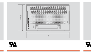
mm (in.) See table, dim. A
Ordering data
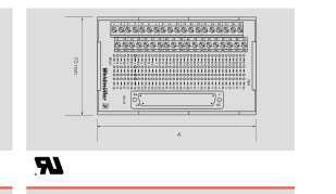
Screw connection LP2N terminal Plug connection Sub-D
150 V 1.5 A -25°C…+50°C -40°C…+70°C
AWG 26…12 7 (.28)
See table, dim. A
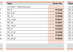
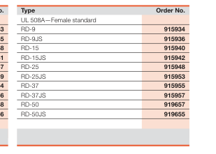
dimensions (mm/in.) Poles Cable Connector Retainer\*
Dim. A
9
Screw
39.88 (1.57)
9
Jackscrew
39.88 (1.57)
15
Screw
55.12 (2.17)
15
Jackscrew
55.12 (2.17)
25
Screw
85.09 (3.35)
25
Jackscrew
85.09 (3.35)
37
Screw
116.84 (4.60)
37
Jackscrew
116.84 (4.60)
50
Screw
149.35 (5.88)
50
Jackscrew
149.35 (5.88)
On TS 35 x 7.5
Accessories
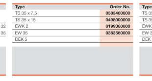
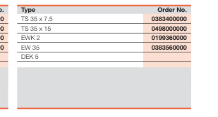
Mounting rail
End bracket
for TS 32 for TS 35
Terminal wire marking
Note : \*Cable connector retainer has either a jackscrew receptacle for a thumb screw or has a mounted screw in the module cable connector.
A.9
Page 10
Interface Units IEC 807-2 - DIN 41652 (Sub-D Connector)
RD
RD
For D-subminiature plug-in
connectors with accessory holes
Male connector
Female connector
with accessory holes†
with accessory holes†
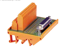
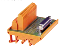
- With mounting foot for TS 32,
TS 35 x 7.5 and TS 35 x 15 rails
- Male and female connectors with
screw/locking system UNC 4/40
- Available with screw connection
A

Technical data
Connection data - Process side
Screw connection
- Type
LP2N terminal
- Control side
Plug connection
- Type
Sub-D
Rated data Rated voltage
150 V
Rated current per contact
1.5 A
Operating temperature
-25°C…+50°C
Storage temperature
-40°C…+70°C
Terminal wire size
AWG 26…12
Insulation stripping length
mm (in.) 7 (.28)
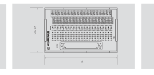
Dimensions Overall width
mm (in.) See table, dim. A
Ordering data
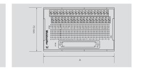
Screw connection LP2N terminal Plug connection Sub-D
150 V 1.5 A -25°C…+50°C -40°C…+70°C
AWG 26…12 7 (.28)
See table, dim. A
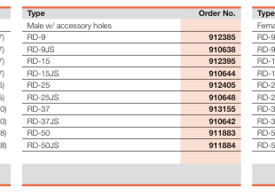
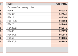
dimensions (mm/in.) Poles Cable Connector Retainer\*
Dim. A
9
Screw
39.88 (1.57)
9
Jackscrew
39.88 (1.57)
15
Screw
55.12 (2.17)
15
Jackscrew
55.12 (2.17)
25
Screw
85.09 (3.35)
25
Jackscrew
85.09 (3.35)
37
Screw
116.84 (4.60)
37
Jackscrew
116.84 (4.60)
50
Screw
149.35 (5.88)
50
Jackscrew
149.35 (5.88)
On TS 35 x 7.5
Accessories
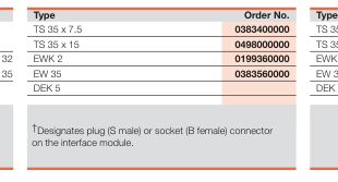
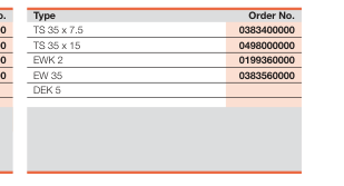
Mounting rail
End bracket
for TS 32 for TS 35
Terminal wire marking
Note : \*Cable connector retainer has either a jackscrew receptacle for a thumb screw or has a mounted screw in the module cable connector.
A.10
Page 11
Interface Units IEC 807-2 - DIN 41652 (Sub-D Connector)
Interface units IEC 807-2
RSSD S/ SUB-D
RSSD Z/ SUB-D
DIN 41652 (Sub-D connector)
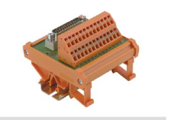
- Pin and socket connector with screw locking
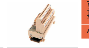
system UNC 4/40
- Tension clamp or screw connection system
- 45 or 87 mm wide
- For mounting on TS32, TS35 x 7.5 and TS35 x 15
A
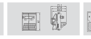

Technical data
Connection data
Connection data
Connection on process side
PCB terminal LM2NZF / Tension clamp
Stripping length
7.0 mm ing length
Connection on control side
D-SUB acc. IEC 807-2 side
Rated data
Rated data
Conversion PCB/plug connector
1:1 ersion PCB/plug connector
Rated voltage V DC
125 V AC/ 150 V DC
Rated current per connection
1.5 A current per connection
Test voltage (~eff)
0.6 kV Test voltage (~eff)
Test torque
Test torque
Storage temperature
-40 °C…+70 °C ure
Ambient temperature (operational)
0 °C…+55 °C ature (operational)
Terminal rail
TS 35 - TS 32 Terminal rail
Insulation coordination (EN 50178)
Insulation coordination (EN 50178)
Surge category
III e category
Pollution severity
2 llution severity
Approvals
Approvals
Standards
EN 50178
Clamping range (rating- / min. / max.)
mm2 1.5 / 0.5 / 2.5
Length x width x height
mm 87.0 x — x 63.6
Note
Ordering data
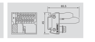
Connection data PCB terminal LPK 2 H / Screw connection 7.0 mm ing length D-SUB acc. IEC 807-2 side
Rated data 1:1 ersion PCB/plug connector 125 V AC/ 150 V DC 1.5 A current per connection 0.6 kV oltage (~eff) 0.40 Nm rque -40 °C…+70 °C ure 0 °C…+55 °C ature (operational) TS 35 al rail
Insulation coordination (EN 50178) III e category 2 llution severity Approvals EN 50178
1.5 / 0.5 / 2.5 45.0 x — x 65.5
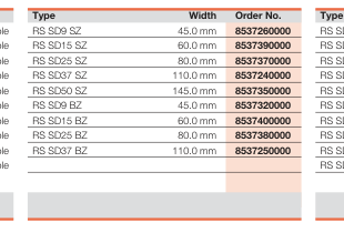
Male connectors
9-pole
Male connectors
15-pole
Male connectors
25-pole
Male connectors
37-pole
Male connectors
50-pole
Female connectors
9-pole
Female connectors
15-pole
Female connectors
25-pole
Female connectors
37-pole
Female connectors
50-pole
Note
Accessories
Note
A.11
Page 12
Interface Units IEC 807-2 - DIN 41652 (Sub-D Connector)
Interface units IEC 807-2
RSSD S/ SUB-D
RSSD S/ SUB-D
DIN 41652 (Sub-D connector)
- Pin and socket connector with screw locking
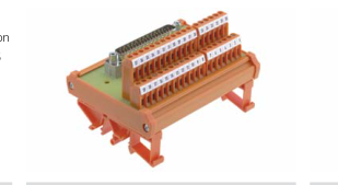
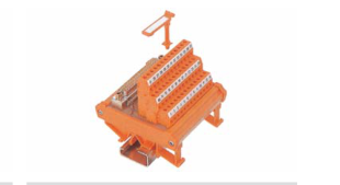
system UNC 4/40
- PCB connection element with screw connection
- Clip-on foot for mounting on TS32, TS35 x 7.5
and TS35 x 15
A
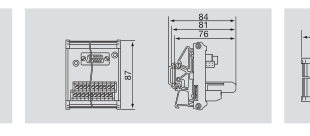

Technical data
Connection data
Connection data
Connection on process side
PCB terminal LP2N ess side
Stripping length
7.0 mm ing length
Connection on control side
D-SUB acc. IEC 807-2 side
Rated data
Rated data
Conversion PCB/plug connector
1:1 ersion PCB/plug connector
Rated voltage V DC
125 V AC/ 150 V DC
Rated current per connection
1.5 A current per connection
Test voltage (~eff)
0.6 kV oltage (~eff)
Test torque
0.50 Nm rque
Storage temperature
-40 °C…+70 °C ure
Ambient temperature (operational)
0 °C…+55 °C ature (operational)
Terminal rail
TS 32, TS 35
Insulation coordination (EN 50178)
Insulation coordination (EN 50178)
Surge category
III e category
Pollution severity
2 llution severity
Approvals
Approvals
Standards
EN 50178
Clamping range (rating- / min. / max.)
mm2 2.5 / 0.5 / 4
Length x width x height
mm 87.0 x — x 76.0
Note
Ordering data
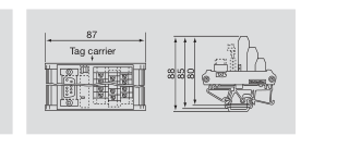
Connection data PCB terminal LP3R ess side 7.0 mm ing length D-SUB acc. IEC 807-2 side
Rated data 1:1 ersion PCB/plug connector 125 V AC/ 150 V DC 1.5 A current per connection 0.6 kV oltage (~eff) 0.50 Nm rque -40 °C…+70 °C ure 0 °C…+55 °C ature (operational) TS 32, TS 35
Insulation coordination (EN 50178) III e category 2 llution severity Approvals EN 50178
2.5 / 0.5 / 4 87.0 x — x 80.0
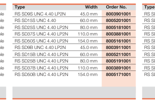
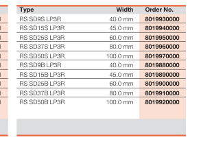
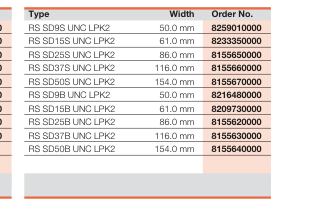
Male connectors
9-pole
Male connectors
15-pole
Male connectors
25-pole
Male connectors
37-pole
Male connectors
50-pole
Female connectors
9-pole
Female connectors
15-pole
Female connectors
25-pole
Female connectors
37-pole
Female connectors
50-pole
Note
Accessories
Note
A.12
Page 13
Supply voltage distributor modules
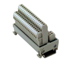
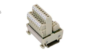
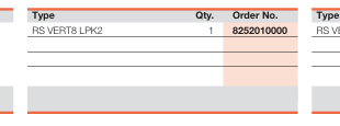
RS VERT 8 LPK2
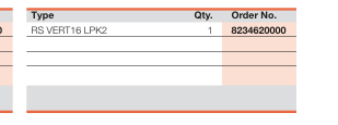
- Distibution module for 2 supply connections to
8 or 16 potential distribution terminals
- 45 mm wide
- Potential distributor designed as two level con-
nection element
Supply Voltage Distributor Modules
RS VERT 16 LPK2
- Total current max. 10 A
- For mounting on rail TS35 x 7.5 and TS35 x 15
A
Technical data
Connection data
Connection data
Connection on process side
PCB terminal LPK 2/ Screw connection
Stripping length
7.0 mm ing length
Conversion PCB/plug connector utor +/- / 2-pole feed
8-way supply voltage distributor +/- / 2-pole feed
Rated data
Rated data
Rated voltage
24 V AC/DC ge
Total current feed, max.
10 A l current feed, max.
Electrical distribution, plus/minus
+/- potential tribution, plus/minus
Storage temperature
-40 °C…+60 °C ure
Ambient temperature (operational)
0 °C…+55 °C ature (operational)
Housing/Terminal rail
RS 45 section /TS 35 l
Insulation coordination (EN 50178)
Insulation coordination (EN 50178)
Surge category/Pollution severity
III /2 category/Pollution severity
Dimensions Clamping range (rating- / min. / max.)
mm2 1.5 / 0.5 / 2.5
Length x width x height
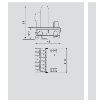
mm 45 x 51.5 x 64
Note
Ordering data
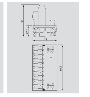
Connection data PCB terminal LPK 2 / Screw connection 7.0 mm ing length 16-way supply voltage distributor +/- / 2-pole feed Rated data 24 V AC/DC ge 10 A l current feed, max. +/- potential tribution, plus/minus -40 °C…+60 °C ure 0 °C…+55 °C ature (operational) RS 45 section /TS 35 l Insulation coordination (EN 50178) III /2 category/Pollution severity
1.5 / 0.5 / 2.5 45 x 92.5 x 64
Note
A.13
Page 14
Supply Voltage Distributor Modules
Supply voltage distributor modules
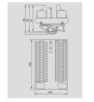
RS VERT 144 LPK3
- Distibution module for 2 supply connections to
72 potential distribution terminals
- Potential distributor designed as three level con-
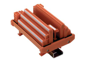
nection element
- Total current max. 20 A
- For mounting on rail TS 32/35
A
Technical data
Connection data
Connection data
Connection on process side
PCB terminal LPK 3 / Screw connection
Stripping length
7.0 mm ing length 72-way supply voltage distributor +/- / 2-pole feed
Conversion PCB/plug connector utor +/- / 2-pole feed Rated data
Rated data
Rated voltage
250 V AC/DC e
Total current feed, max.
20 A l current feed, max.
Electrical distribution, plus/minus
+/- potential tribution, plus/minus
Storage temperature
-40 °C…+60 °C ure
Ambient temperature (operational)
0 °C…+55 °C ature (operational)
Housing/Terminal rail , TS 35
RS 100 section /TS 32, TS 35
Insulation coordination (EN 50178)
Insulation coordination (EN 50178)
Surge category/Pollution severity
III /2 category/Pollution severity
Dimensions Clamping range (rating- / min. / max.)
mm2 1.5 / 0.5 / 2.5
Length x width x height
mm 104 x 160 x 87
Note
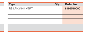
Ordering data
Note
A.14
Page 15
Interface Units with RJ45 Plug Connectors
Interface units with RJ45
RS RJ45 2WAY
RS RJ45
plug connectors
- Direct coupling of PC and modem in control
cabinet
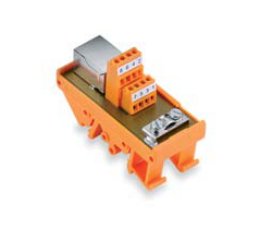
- Connection of typical office equipment
- Data rate Cat5 100 Mbit
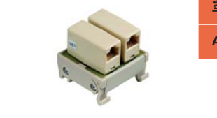
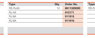
- Available as RJ 45/screw connection conversion
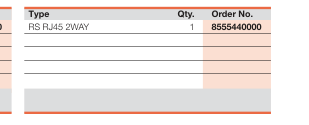
or as RJ 45 coupling
- For mounting on rail TS 32/35
A
Technical data
Connection data
Connection data
Connection on process side g-in connector
screw connection/ RJ45 plug-in connector
Connection on control side g-in connector
screw connection/ RJ45 plug-in connector
Design emale connector
RJ45 female connector
Conversion PCB/plug connector
1:1 ersion PCB/plug connector
Rated data
Rated data
Rated current per connection
1.5 A current per connection
Number of signals
8 shielded signals
Contact material 6µ AU
phosphor- bronze 6µ AU
Storage temperature
-40 °C…+70 °C ure
Ambient temperature (operational)
0 °C…+55 °C ature (operational)
Housing ection
RS 70 section
Terminal rail
TS 32, TS 35
Insulation coordination (EN 50178)
Insulation coordination (EN 50178)
Surge category/Pollution severity
II /2 category/Pollution severity
Dimensions Clamping range (rating- / min. / max.)
mm2 1.5 / 0.5 / 1.5
Length x width x height
mm 70 x 30 x 48
Connect shielding of data line to protective ground at one end
Note
Ordering data
Connection data 2 x RJ45 connector J45 plug-in connector 2 x RJ45 connector J45 plug-in connector RJ45 female connector 1:1, RJ45 coupling connector Rated data 1.5 A current per connection 8 shielded signals phosphor- bronze 6µ AU -40 °C…+70 °C ure 0 °C…+55 °C ature (operational) RS 70 section TS 32, TS 35 Insulation coordination (EN 50178) II /2 category/Pollution severity
70 x 38 x 48
Connect shielding of data line to protective ground at one end
Note
A.15
Page 16
ELCO Interface Unit
ELCO
ELCO
Cable interface units designed
according to UL 508A recognition
Male† connector
Female† connector
Standard
Standard
A
Technical data
Connection data - Process side
Screw connection
- Type
LP2N terminal
- Control side
Plug connection
- Type
ELCO
Rated data Rated voltage
125 V
Rated current per contact
3.5 A
Operating temperature
-25°C…+50°C
Storage temperature
-40°C…+70°C
Terminal wire size
AWG 26…12
Insulation stripping length
mm (in.) 7 (.28)
Dimensions Overall width
mm (in.) See table, dim. A
Ordering data
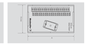
Screw connection LP2N terminal Plug connection ELCO
125 V 3.5 A -25°C…+50°C -40°C…+70°C
AWG 26…12 7 (.28)
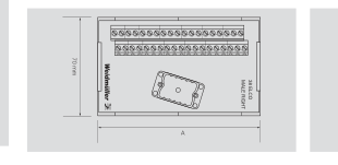
See table, dim. A
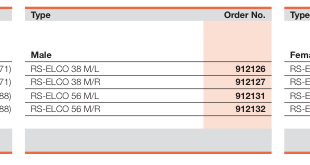
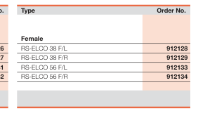
dimensions (mm/in.) Cable Connector
Connector
Poles Orientation\*
Retainer Dim. A
38 Left Center Screw 119.63 (4.71)
38 Right Center Screw 119.63 (4.71)
56 Left Center Screw 174.75 (6.88)
56 Right Center Screw 174.75 (6.88)
Accessories
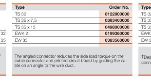
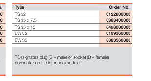
Mounting rail
End bracket
for TS 32 for TS 35
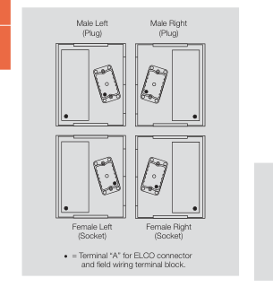
Note : \*The purpose for the different designations, “left” and “right” are relative to the direction the interconnecting cable is plugged into the interface module. ELCO connector cables generally use #14 AWG wire which does not bend easily.
A.16
Page 17
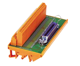
T-CON Interface Unit
T-CON
Multi-pole cable connector
for SCSII applications
Female connector with accessory holes
A
Technical data
Connection data - Process side
Screw connection
- Type
LP2N terminal
- Control side
Plug connection T-Con
- Type
Rated data Rated voltage
60 V
Rated current per contact
100 mA
Operating temperature
-25°C…+50°C
Storage temperature
-40°C…+70°C
Terminal wire size
AWG 26…12
Insulation stripping length
mm (in.) 7 (.28)
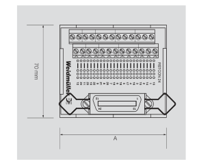
Dimensions Overall width
mm (in.) See table, Dim. A
Ordering data
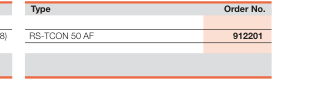
dimensions (mm/in.) Poles Connector Retainer
Dim. A
50
Bale Latch
149.35 (5.88)
Accessories
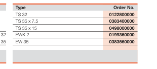
Mounting rail
End bracket
for TS 32 for TS 35
Note :
A.17