
894 ETC2
Document overview
- Manufacturer or author: Provided By www.digicamel.com(FREE DATASHEET DOWNLOAD SITE)
- PDF pages: 5
Technical content
500 kHz / 1 MHz Precision LCR Meter Models 894 & 895 Technical data subject to change © B&K Precision Corp. 2017 www.bkprecision.com Industry-Leading Performance The 894 and 895 are high accuracy LCR meters capable of measuring inductance, capacitance, and resistance of components and materials at DC or from 20 Hz to 500 kHz or 1 MHz respectively. These LCR meters provide flexible AC and DC test signal configuration. AC test signal voltage is variable from 5 mVrms to
2 Vrms, the AC current is adjustable up to
66.7 mArms, depending on the AC impedance selected, and a DC bias signal can be added. The vivid 4.3-inch TFT LCD offers a clear view of all measured and setting values along with BIN sorting comparator results and a handy Zoom feature that enlarges the measured values to full screen. With a basic accuracy of 0.05%, auto level control (ALC), open / short / load correction and cable length compensation, these meter are perfect tools for R&D, manufacturing and quality control applications. Features & Benefits n AC test signal voltage adjustable up to 2 Vrms n 3 AC current ranges, selectable via 30 Ω, 50 Ω or 100 Ω internal AC impedance. The 30 Ω setting provides up to 66.7 mArms of drive current, sufficient for larger inductors and transformers. n Built-in DC bias source adjustable from -5V to +5V / -50 mA to +50 mA n Fast measurement speed up to 13 ms/reading to increase manufacturing throughput n Adjustable measurement speed for fast readout or better accuracy n 201-point programmable list sweep function providing ability to sweep frequency, AC and DC bias voltage/current levels n Auto-level control to maintain the measurement signal applied to the DUT at a constant level n Test signal voltage and current monitoring n BIN comparator function to sort components in up to 10 bin locations n Handler interface for easy integration with a component handler n 1 m and 2 m cable compensation n 4-terminal fixture and Kelvin clip test leads included n Transformer test function with optional transformer test fixture TL89T1 n Versatile trigger functionality (internal, external, bus and manual) n Standard USB, LAN, and GPIB (895 only) interface for remote control using SCPI commands DC Biasing Both the 894 and 895 feature a DC bias source which allows the meter to apply a DC signal to the device under test to simulate in-circuit conditions. DC biasing is commonly used to measure capacitance of ceramic, MLCC, polyester and other capacitors with high dielectric constants. These type of capacitors exhibit a significant change in capacitance with a DC voltage applied. By controlling the DC voltage, users can obtain a more deterministic measurement result. Other applications include evaluation of cored-inductors and junction capacitance of semiconductor devices. The DC bias source is adjustable from -5V to +5V / -50 mA to +50 mA. Additionally the voltage or current levels can be swept while logging the resulting capacitance. Model 894 895 Measurement parameters L, C, R, G, X, Z, Y, B, θ, Q, D, DCR Basic accuracy 0.05% DCR measurement range 0.01 Ω - 100 MΩ Test frequency range 20 Hz - 500 kHz 20 Hz - 1 MHz
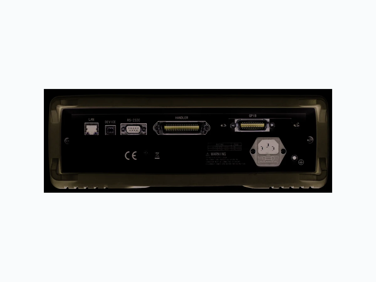
500 kHz / 1 MHz Precision LCR Meter Models 894 & 895 www.bkprecision.com Front panel USB host port Connect your USB flash drive to conveniently save and recall measurement data logs, settings, and screenshots. Variable test signals The instrument provides settable voltage levels from 5 mVrms to 2 Vrms to evaluate your DUT. Intuitive user interface Easily change test parameters using the menu-driven front panel keypad. 4.3” TFT high resolution color display Pass/Fail LED indicators Rear panel GPIB interface (Model 895 only) Handler interface 36-pin connector to interface with component handler via input/output control signals. Includes bin and list sweep comparator results and end of measurement (EOM) indicator output signals, external trigger, and key lock input signal. RS232 interface LAN interface USB interface AC input Zoom display mode Enlarge the displayed values for easy viewing with a touch of a button. The voltage and current across the DUT are also monitored in zoom display mode. Built-in DC bias source
500 kHz / 1 MHz Precision LCR Meter Models 894 & 895 www.bkprecision.com Use the built-in linear and logarithmic sweep function, supporting up to 201 sweep points, to conveniently display, analyze and store primary and secondary parameters of a component. Sweep test frequency, AC source voltage and current levels, DC bias source voltage and current levels. A delay can be programmed after each sweep point. The list sweep can be triggered internally, manually or externally and executed in sequence or step mode. Programmable List sweep Quickly sort components using the instrument’s 9 primary BINs, a secondary BIN and out-of-specification BIN. The results can be displayed in a table on-screen or output via the handler interface. High and low limits for each bin can be set up in absolute, tolerance or sequential mode with Pass/Fail indicator. Bin sorting function Integrate your LCR meter into an automated test system and control it from a PC using SCPI commands via the RS232, USB, LAN, or GPIB (895 only) interface. Remote PC control Flexible test accessories Standard accessories shipped with each unit are Kelvin clip test leads for 4-wire measurements, a test fixture, and shorting bar. The optional transformer test fixture allows users to measure transformer parameters. Kelvin clips (TL89K1) Transformer test fixture (TL89T1) Test fixture (TL89F2) Shorting bar (TLBSB) Transformer measurements (optional) Diagram showing the TL89T1 connected to a transformer under test. Using optional test fixture TL89T1, the 894 and 895 can test the primary and secondary inductance L1, L2, turn ratio (N, 1/N), mutual inductance (M), and primary and secondary direct-current resistance (R2) of a transformer directly. Additionally, the two common transformer parameters winding equivalent capacitance C o and leakage inductance Lk can be characterized indirectly. Powerful Features Included Optional
500 kHz / 1 MHz Precision LCR Meter Models 894 & 895 4 www.bkprecision.com Test Signal Frequency Model Range Minimum resolution Accuracy 894 20 Hz - 500 kHz 0.01 Hz 0.01 % 895 20 Hz - 1 MHz Specifications Measurements Cable length compensation 0, 1, & 2 meters Math operations Direct reading, ∆ABS, ∆% Trigger mode Internal, Manual, External, Bus Delay time setup Time from trigger to start: 0 to 60 seconds Resolution: 1 ms Comparator (Bin sorting) 10-bin sorting, primary bins BIN1-BIN9 and OUT, secondary bin AUX Bin counter: 0 to 999,999 PASS/FAIL indication via front panel LED or handler interface signal Test Signal Levels AC source (ALC* OFF) Voltage Accuracy 10% x set voltage ± 2mV Voltage Level Resolution 5 mVrms - 100 mVrms 100 µVrms 100 mVrms - 1 Vrms 1 mVrms
1 Vrms - 2 Vrms 10 mVrms
Current Accuracy 10 % x set current ± 10 µA Current Range Impedance 166.7 µArms - 66.7 mArms 30 Ω 100.0 µArms - 40.0 mArms 50 Ω 50.0 µArms - 20.0 mArms 100 Ω AC source (ALC* ON)1 Voltage Range 10 mVrms – 1 Vrms Accuracy 6% x set voltage ± 2 mV Current Range 100 µArms - 10 mArms Accuracy 6 % x set current ± 10 µA DC bias source Voltage Range -5 V to +5 V Accuracy 1 % x set voltage ± 5 mV Resolution 0.01 mV Current Range -50 mA to +50 mA Accuracy 1 % x set current ± 50 µA Resolution 0. 1 µA *Auto Level Control 1: Resolution and impedance see AC source (ALC OFF) specification Measurements Measurement parameters L, C, R, G, X, Z, Y, B, θ, Q, D, DCR Transformer measurement parameters2 L2A, L2B, N, 1/N, M Basic accuracy 0.05 % AC source Output impedance (± 2%) 30 Ω, 50 Ω, 100 Ω Typical measurement time (≥10 kHz) (excluding display refresh time) Fast 13 ms / measurement Medium 67 ms / measurement Slow 187 ms / measurement Equivalent circuit Series, Parallel Range mode Auto, Hold Averaging 1-255 measurements Correction function Open, Short and Load correction List sweep 201 sweep points Sweep test frequency, test signal AC voltage, test signal AC current, test signal DC bias voltage and test signal DC bias current Measurement parameters Primary and secondary Sweep modes Linear or logarithmic Trigger mode Sequential and Step Comparator One pair of lower and upper limits for primary or secondary parameter (user selectable) Internal non-volatile memory Save / recall 40 setups General External USB memory Save / recall setups, screenshots, measurements and sweep data logs Remote interface USB (USBTMC or virtual COM), RS232, LAN, GPIB (895 only) Handler interface 36-pin connector AC input Voltage 110/220 VAC ±10% Frequency 47 – 63 Hz Power consumption Max. 80 VA Operating temperature 0 °C to 40 °C Storage temperature -10 °C to 70 °C Relative humidity Up to 80% Display 4.3” TFT color display Dimensions (WxHxD) without bezel: 280 mm × 88 mm × 370 mm with bezel: 369 mm × 108 mm × 408 mm Weight 5 kg (11 lbs) Safety EN61010-1:2001, EU Low Voltage Directive 2006/95/EC Electromagnetic Compatibility Meets EMC Directive 2004/108/EC, EN61326-1:2006 Three-Year Warranty Standard accessories AC power cord, 4-wire Kelvin clip test lead, 4-terminal test fixture, shorting bar, certificate of calibration, test report Optional accessories Transformer test fixture TL89T1 Valid after 30 minutes of warm up time, operating at 23 °C ± 5 °C 2: Requires optional fixture TL89T1
500 kHz / 1 MHz Precision LCR Meter Models 894 & 895 www.bkprecision.comv011917 Measurement Accuracy The chart below depicts the basic measurement accuracy under the following conditions: AC test signal level 0.5 Vrms or 1 Vrms, measurement speed Slow or Medium, cable length 0 m, DC bias OFF, Dx ≤ 0.1 or Qx ≤ 0.1 respectively. When selecting measurement speed Fast, double the accuracy value obtained from the chart. For more detailed measurement accuracy specifications and other test conditions, refer to the user manual. DCR Accuracy: A(1 + Rx / 5 MΩ + 16 mΩ / Rx)[%] ±0.2 mΩ A=0.25 for slow & medium speed, A=0.5 for fast speed