
881 LITTELFUSE
Document overview
- Manufacturer or author: Provided By www.digicamel.com(FREE DATASHEET DOWNLOAD SITE)
- PDF pages: 3
Technical content
Features
Electrical Characteristics for Series % of Ampere Rating Opening Time 100% 1 Hour, Min. 200% 60 Seconds, Max.
Applications
- Blade Servers
- Routers
- High-power Battery Systems
- Power Factor Correction (PFC) in high wattage power supplies
- Power Distribution Units (PDUs)
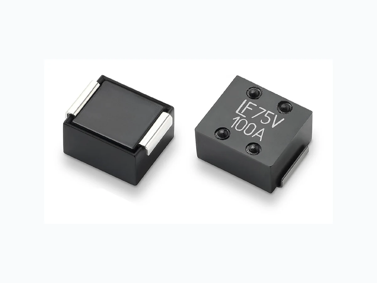
- Surface mount package: 12.5mm x 10.0mm
- Suitable for reflow soldering
- 60A to 100A ratings
- Lead-free and RoHS compliant AGENCY AGENCY FILE NUMBER AMPERE RANGE E7161 1 60A − 100A Ampere Rating (A) Amp Code Max Voltage Rating (V) Interrupting Rating Nominal Cold Resistance (mOhms) Nominal Voltage Drop * (mV) Nominal Melting ** I2t (A2sec) Agency Approvals 60 060. 75Vdc 1500A @75Vdc 0.81 75 1050 X 70 070. 0.7 4 85 1250 X 80 080. 0.56 80 3300 X 90 090. 0.54 85 4300 X 100 100. 0.45 80 6900 X Ampere Rating In (A) Typical Case Temperature Rise (°C) * @ 50%In @ 75%In @ 100%In 60 14 35 60 70 15 37 70 80 16 39 85 90 19 49 105 100 23 53 120 Electrical Specifications by Item Thermal Characteristics * Typical values based on tests conducted with fuse mounted on FR-4 circuit board of 0.062” (1.6 mm) thickness with 6 oz. (210 µm) Cu. * Nominal Voltage Drop measured at 100% rated Current. ** Nominal Melting I2t measured at 1500A.
© 2017 Littelfuse, Inc. Application testing is strongly recommended. Specifications are subject to change without notice. Revised: 03/31/17 Surface Mount Fuses High-Current > 881 Series PERCENT OF RATING AMBIENT TEMPERATURE 100 120 140 160 25°C Average Time Current Curves Reflow Condition Pb – Free assembly Number of allowed reflow cycles 3 Pre Heat - Temperature Min (Ts(min)) 150°C - Temperature Max (Ts(max)) 200°C - Time (Min to Max) (ts) 60 – 180 secs Average ramp up rate (Liquidus Temp (TL) to peak 5°C/second max. TS(max) to TL - Ramp-up Rate 5°C/second max. Reflow - Temperature (TL) (Liquidus) 217°C - Temperature (tL) 60 – 150 seconds Peak Temperature (TP) 260+0/–5 °C Time within 5°C of actual peak Temperature (tp) 20 – 40 seconds Ramp-down Rate 5°C/second max. Time 25°C to peak Temperature (TP) 8 minutes max. Do not exceed 260°C Soldering Parameters T emperature Re-rating Curve Note: 1 . Rerating depicted in this curve is in addition to the standard derating of 25% for continuous operation. Example: For continuous operation at 70°C, the fuse should be re-rated as follows: I = (0.75)(0.90)IRAT = (0.675)IRAT 2. The temperature re-rating curve represents nominal conditions. For questions about the temperature re-rating curve, please consult Littelfuse technical support assistance. Time Temperature TP TL TS(max) TS(min) tP tL tS time to peak temperature (t 25ºC to peak) Ramp-down Ramp-up Preheat Critical Zone TL to TP 0.001 0.01 0.1 100 10 1001 0001 0000 Time in second Current in Amperes 60A 70A 80A 90A 100A
© 2017 Littelfuse, Inc. Application testing is strongly recommended. Specifications are subject to change without notice. Revised: 03/31/17 Surface Mount Fuses High-Current > 881 Series Notes: 1. Based on loading at 75% of ampere rating when mounted using recommended pad layout. 2. Usage outside of stated operating temperature range requires testing in application. Maintain case temperature below 150°C in application. Thermal Shock MIL -Std 202 Method 107 Test Condition B (-65°C to 125°C, 5 cycles). Moisture Resistance MIL -Std 202 method 106 High Humidity (90-98%RH), Heat (65°C) Vibration MIL -STD-202, Method 201 (10-55 Hz) Mechanical Shock MIL -STD-202, Method 213, Test Condition I (100 G’s peak for 6 milliseconds) Resistance to Solder Heat MIL -Std 202 Method 210 Test Condition B (10sec at 260°C) Solderability MIL -STD-202 Method 208 MSL Test Level 1 J-STD-020 Salt Fog MIL -Std 202 Method 101 Test Condition B (5% NaCL solution, 48 hours exposure) Packaging Packaging Option Packaging Specification Quantity Quantity & Packaging Code 24mm Tape and Reel EIA-481 Rev. D (IEC 60286, part 3) 500 UR Materials Body: Thermoplastic, RTI 150°C Terminations: Tin-plated Copper Product Marking Brand logo, Voltage Rating, and Ampere Rating Operating T emperature 1 2 -55° to +100°C with proper derating Product CharacteristicsDimensions Part Numbering System 0881 100. U R SERIES AMP Code* QUANTITY Code PACKAGING Code Refer to Electrical Specifications table U = 500 Pieces R = Tape and Reel *Example: 60 amp product is 0881060.UR (100 amp product shown above). 11.2 (0.440“) 10.0 (0.393“) 6.3 (0.248“) 8.0 (0.314“) 6.4 (0.252“) 6.0 (0.236“) 6.8 (0.267“) 12.5 (0.492“) 1.6 (0.062") 3.0 (0.118") 10.0 (0.393“) Units in mm (inch) Recommended Pad Layout 6 oz. (210µm) minimum Cu layer