


 Download PDF
87615 MOLEX
Document overview
- PDF pages: 6
Technical content
Page 1
Page 2
INTRODUCTION
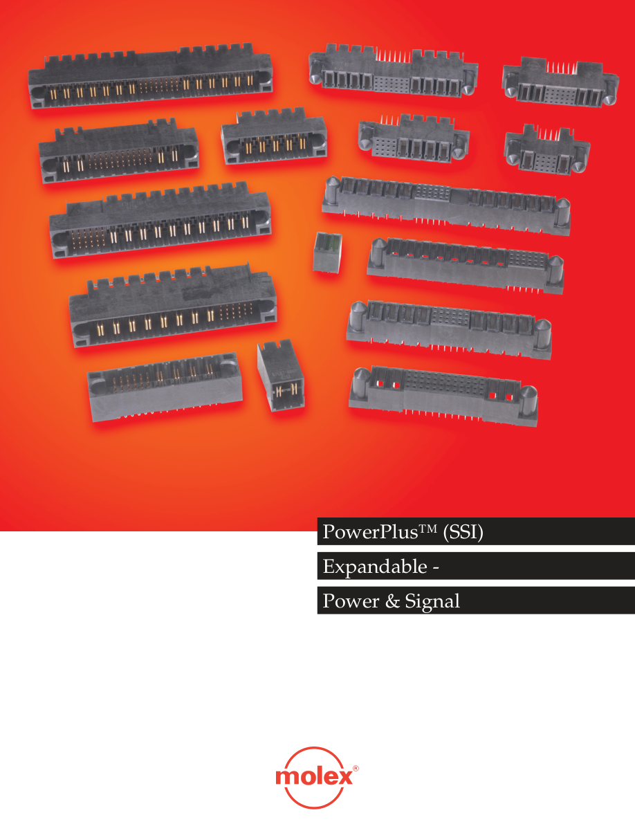
Molex’s successfully introduced a new series of power connectors that conform to Server System Infrastructure (SSI) open specifi cation (http://www.ssiforum.org). The DPS and MPS offer a standard variation of 2 & 11 power blades with mixed layout of 24 signal pins. The contact support up to 30 amperes of current. With demand for more fl exibility and options in variations, Molex have further expanded the series to cater to the needs and requirement from our customers.
FEATURES AND BENEFITS
Recessed pins-sequential mating (Last-Mate-First-Break) allows hot swapping of power supply units Guide Pockets (headers) or guide posts (receptacles) facilitate easy blind-mating Shrouded headers prevent contact damage Stamped and selectively plated power contacts provide greater electrical reliability
APPLICATIONS
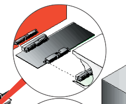
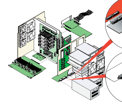
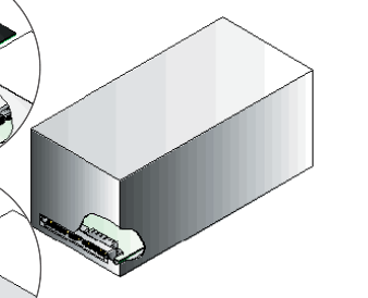
They feature recessed signal-pins and sequential mating (Last-Mate- First-Break) that allows hot-swapping of power supply units on the male side. The receptacle could also provide for LMFB with recess power blade. The selection options include any number of power (up to 20) or signals (up to 128), placing power or signal at different location, fork lock or screw mount, AC or DC current (different pitch), Guide post option, Standard and Long Power blades. Molex offers standard through-hole right angle headers and receptacles as well as through- hole and press fi t vertical receptacles.
Rigid tails for easy PCB insertion Metal forklocks or screw mounts for strong board retention reduce board warpage during soldering High temperature thermoplastic housing material ensures thermal reliability
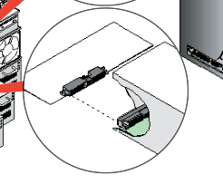
Page 3
SELECTION GUIDE
| (1) Gender | - Plug (Male) - Receptacle (Female) |
| (2) Connector Orientation | - Vertical - Right Angle |
| (3) Termination Method | - Through Hole - Press-Fit |
| (4) Type | - Power-Signal-Power (P-S-P) - Power(Alpha)-Signal (Pa-S) - All Power (AP) - Signal-Power(Beta) (S-Pb) - AC Power/DC Power (AC/DC) |
| (5) Power & Signal | - Number of power at Alpha. Example, 2 power pins at Alpha = 2 Pa - Number of Signal pins. Example, 24 signal pins = 24 S - Number of power at Beta. Example, 3 power pins at Beta = 3 Pb |
| (6) Recess | - Recess Power only on Receptacle Power Alpha or Beta. Example, Recess Pa #1, Pb #3 etc. - Recess Signal only on Plug. Example, Recess Signal at A3, B4 etc. 1 2 3 4 5 6 D C B A Plug Recess Signal Receptacle Recess Power |
| (7) Retention to PCB | - Board Lock - Screw Mount |
| (8) Guide Post | - With Guide Post - Without Guide Post |
| (9) Pitch | - DC Power: 6.35mm (.25”) Pitch / 5.08mm(.20”) Pitch - AC Power: 7.62mm (.30”) Pitch |
Page 4
SPECIFICATIONS
Electrical
Mechanical
Voltage:
Mating Force:
Power – 48V
Power – 6.95N (1.56 lb) per pin
Signal – 48V
Signal – 1.00N (.22 lb) per pin
Current:
Unmating Force:
Power – 30A
Power – 2.23N (.50 lb) per pin
Signal – 2.5A
Signal – 0.10N (.022 lb) per pin
Contact Resistance:
Durability: 100 cycles
Power – 0.5 mΩ max. Signal – 20 mΩ max. Dielectric Withstanding Voltage: Power – 2,500V AC Signal – 1,000V AC Insulation Resistance: Power – 20,000 MΩ min. Signal – 5,000 MΩ min.
SSI - MPS
Physical Unmated Height: 12.09mm (.476”) Housing: Black High Temperature Thermoplastic, Glass-fi lled, UL 94V-0 Contact: Copper (Cu) Alloy Plating: Contact – 0.76µm (30µ”) Gold (Au) Tail – 2.54µm (100µ”) Tin/Lead (Sn/Pb) Underplating – Nickel (Ni) Operating Temperature: -40 °C to +105
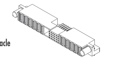
87616
Right Angle,
Through Hole Receptacle
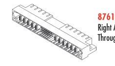
Right Angle, Through Hole Header
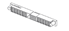
Press-Fit Receptacle
SSI - DPS
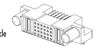
87607
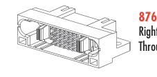
Right Angle, Through Hole Receptacle
87606
Right Angle,
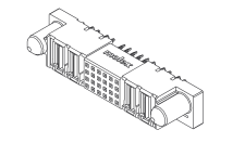
Through Hole Header
Vertical, Press-Fit Receptacle
Page 5
Power-Signal-Power (P-S-P)
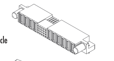
87632
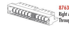
Right Angle, Through Hole Header
All Power
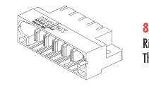
87658 Right Angle, Through Hole Header
Power(Alpha)-Signal (Pa-S)
Right Angle, Through Hole Receptacle
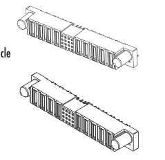
87622 Vertical, Through Hole Receptacle
87633 Vertical, Press-Fit Receptacle
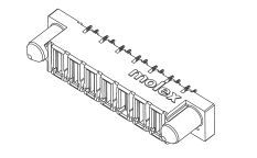
87691 Vertical, Press-Fit Receptacle
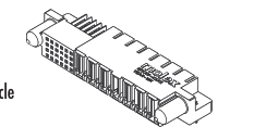
87700
Right Angle, Through Hole Receptacle
87696 Right Angle,
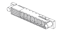
Through Hole Header
87697 Vertical, Press-Fit Receptacle
Page 6
Signal-Power(Beta) (S-Pb)
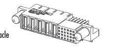
87668
Right Angle,
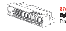
Through Hole Receptacle
87667 Right Angle,
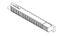
Through Hole Header
87710 Vertical, Press-Fit Receptacle
AC/DC
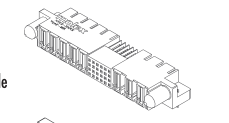
87664
Right Angle,
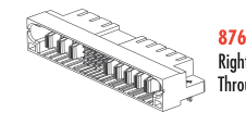
Through Hole Receptacle
87663 Right Angle,
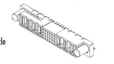
Through Hole Header
87734 Right Angle, Through Hole Receptacle
Bringing People & Technology Together, Worldwide
SM
Far East North Headquarters Far East South Headquarters
America Headquarters Lisle, Illinois 60532 U.S.A.
Yamamoto, Kanagawa, Japan
Jurong, Singapore
Tel: 1-800-78Molex
Tel: 81-462-65-2324
Tel: 65-6268-6868
Fax: 1-630-969-1352
Fax: 81-462-65-2366
Fax: 65-6265-2985
European Headquarters
Corporate Headquarters
Munich, Germany
2222 Wellington Court
Tel: 49-89-413092-0
Lisle, Illinois 60532 U.S.A.
Fax: 49-89-401527
Tel: 1-630-969-4550 Fax: 1-630-969-1352
© 2003, Molex