
DATASHEET SEARCH SITE
Document overview
- Manufacturer or author: Provided By www.digicamel.com(FREE DATASHEET DOWNLOAD SITE)
- PDF pages: 6
Technical content
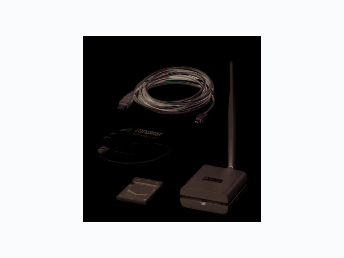
Master with antenna for the WIN signal tower wireless system PSD-S WIN MA/UL © PHOENIX CONTACT Data sheet The WIN (Wireless Information Network) wireless system is an inexpensive, wireless-based machine data acquisition system (MDA system). It enables wireless transmission of signal statuses from sev- eral signal towers and therefore central monitoring on the PC of up to 50 different machines. A master as receiving unit, at least one slave as wireless ele- ment and software for displaying and evaluating the signal statuses make up the wireless system. The following is included in scope of supply: – One master with antenna including accessories –O n e U S B c a b l e – Software CD with WIN software The master is the receiving unit for the signals that are trans- mitted by the slave. The master is connected to the USB connection of a PC. You can therefore display and evaluate received signal statuses with the WIN software on the PC and store them in a data- base. WIN master features – Use of the 915 MHz frequency band – Can operated parallel to ot her wireless applications (e. g., WLAN, Bluetooth) – Simultaneous detection of up to 50 wireless elements (slaves) WIN software features – License-free software for wireless monitoring of the ma- chine park on the PC at a glance – Scope of functions: monitoring of system statuses, trou- bleshooting, wireless path diagnostics, productivity anal- ysis for increasing machine efficiency and availability, storing in a database – Easy installation – No programming knowledge required – Error messages from the software can be sent via e-mail NOTE: This version of WIN is only approved for use in North America. NOTE: Do not use the WIN system for safety-related applications! Make sure you always use the latest documentation. It can be downloaded from the product at www.phoenixcontact.net/products. 8642_en_00 2013-02-04
8642_en_00 PHOENIX CONTACT 2 2T a b l e o f c o n t e n t s Description Type Order No. Pcs. / Pkt. Master with antenna for the WIN signal tower wireless system, with USB in- terface, voltage supply via USB interface, software CD, USB cable (3 m), four rubber feet and material for wall mounting of the master PSD-S WIN MA/UL 2701664 1 3O r d e r i n g d a t a Additional product required Type Order No. Pcs. / Pkt. Slave with C-UL-US approval for creating or extending the WIN signal tower wireless system, 24 V AC/DC, black PSD-S WIN SL/UL 2701565 1 Set comprises Type Order No. Pcs. / Pkt. Set with C-UL-US approval for the WIN signal tower wireless system, con- sisting of one master with antenna, three slaves, software CD, USB cable (3 m), four rubber feet, and mounting material for wall mounting the master PSD-S WIN SET-1MA-3SL/UL 2701563 1 Starter kit with C-UL-US approval for the WIN signal tower wireless system, consisting of one master with antenna, three slaves, nine LED permanent light elements (red, yellow, green), three connection elements, three mounting feet with integrated tube, software CD, USB cable (3 m), four rub- ber feet, and mounting material for wall mounting the master PSD-S WIN STARTERKIT/UL 2701564 1 Documentation Type Order No. Pcs. / Pkt. User manual, German, wireless system for signal towers, only approved for use in North America! UM DE PSD-S WIN/UL - - User manual, English, wireless system for signal towers, only approved for use in North America! UM EN PSD-S WIN/UL - - User manual, French, wireless system for signal towers, only approved for use in North America! UM FR PSD-S WIN/UL - -
8642_en_00 PHOENIX CONTACT 3
4 Technical data
Dimensions (in mm) Width 77 mm Height 188 mm Depth 117 mm Note on dimensions Height and depth when antenna is perpendicular 117 3,5 30,5 188 General data Material Acrylonitrile butadiene styrene (ABS) Color black Weight 106 g Ambient temperature (operation) -20 °C ... 50 °C Degree of protection IP20 Diagnostics / Message Wireless connection / LED Electrical data of the master Interfaces USB Operating voltage 5 V DC (USB; only use USB cables with a maximum length of 3 m.) Inrush current 100 mA Current consumption max. 100 mA Wireless interface Modulation type 2 FSK Frequency range 913 Hz ... 917 Hz Frequency band 915 MHz ISM band Transmission power 10 dBm (at 50 Ohm) Range 300 m, maximum Transmission speed 38.4 kbps (can be adjusted via WIN software) , 76.8 kbps (default) Wireless modules that can be connected Up to 50 (2701565 PSD-S WIN SL/UL)
8642_en_00 PHOENIX CONTACT 4
5 Scope of supply
Figure 1 Elements within the scope of supply Key:
1 Master
2 USB cable
3 CD with WIN software
4 Fixing element 1 (screw to master; two screws included)
5 Fixing element 2 (screw to the wall)
6 Rubber feet
Conforms with guidelines: FCC Part 15.249/IC: RSS-210 Issue 8, RSS-GEN Issue 4, RSS-102 Issue 4 For the latest approvals, please visit www.phoenixcontact.net/products. Wireless licences Country ID USA , Canada
8642_en_00 PHOENIX CONTACT 5 6U s e l i m i t a t i o n
6.1 FCC approval
FCC = Federal Communications Commission This device complies with Part 15 of the FCC regulations. Operation is subject to the following two requirements: 1. This device may not cause harmful disturbances. 2. This device must withstand all disturbances received, in- cluding disturbances which could lead to unintentional operation. Normally, the following FCC warning applies: The user's permission to operate the equipment could be de- clared void by making any changes or modifications to this unit which are not expressly approved by the party responsi- ble for compliance. Contains: transmitter module FCC ID: ZGHWIN1
6.2 IC approval
This device complies with the RSS rule(s) of Industry Canada. Operation is subject to the following two requirements: 1. This device may not cause harmful disturbances. 2. This device must withstand all disturbances received, in- cluding disturbances which could lead to unintentional operation. Contains: transmitter module IC: 9619A-WIN1 7S a f e t y n o t e s – Do not use the system for sa fety-related applications. – Also please observe the documentation on the individual elements of the signal tower (data sheets, package in- serts) and the user manual regarding the wireless system for signal towers. – Use only with 24 V signal towers. – Only a qualified electrician can connect the system. – Only use power supply units wi th safe isolation and PELV voltage (protection class 2). – This device does not replace personal protective equip- ment (e.g., protective goggles, foot protection, etc.). – This system cannot eliminate the need for or replace pro- tective machine equipment, a safety circuit, a protective device, a safety regulation or supervision. – Test this device and all pr otective machine equipment and safety devices at the start of each shift to ensure that it is functioning correctly. – Always take the machines out of operation when replac- ing worn parts. – When guards are removed, always implement the “OS- HA lock-out/tag-out” regulations. NOTE: This version of WIN is only approved for use in North America. CAUTION: Observe the following safety notes when using the WIN wireless system!
8642_en_00 6PHOENIX CONTACT GmbH & Co. KG • 32823 Blomberg • Germany www.phoenixcontact.com
8 Mounting the master
You can mount the master either on the wall or position it next to the PC. If you do not mount the master on the wall, stick the four rub- ber feet provided to the four corners on the underside of the master. They serve to protect against scratching and slipping. If you mount the master on the wall, proceed as follows. Figure 2 Mounting the master on the wall
- Screw the fixing element 1 to the master (fig. A). Use the screws supplied.
- Screw the fixing element 2 to the wall (fig. B). The screws are not supplied.
- Snap the master with fixing element 1 into fixing element 2 (fig. C).
9 Master supply voltage
The WIN master is supplied with voltage from the PC con- nected to it via the USB connection of the PC.
10 Diagnostics
The status of the wireless connection is indicated by the LED band that surrounds the master.
11 WIN software
The ideal wireless connection is achieved when as few objects as possible influence the WIN master and WIN slave. B C A Meaning Red LED Green LED No wireless connection to the WIN slave Wireless connection to at least one WIN slave Please obtain information on the WIN software from the corresponding User Manual.