
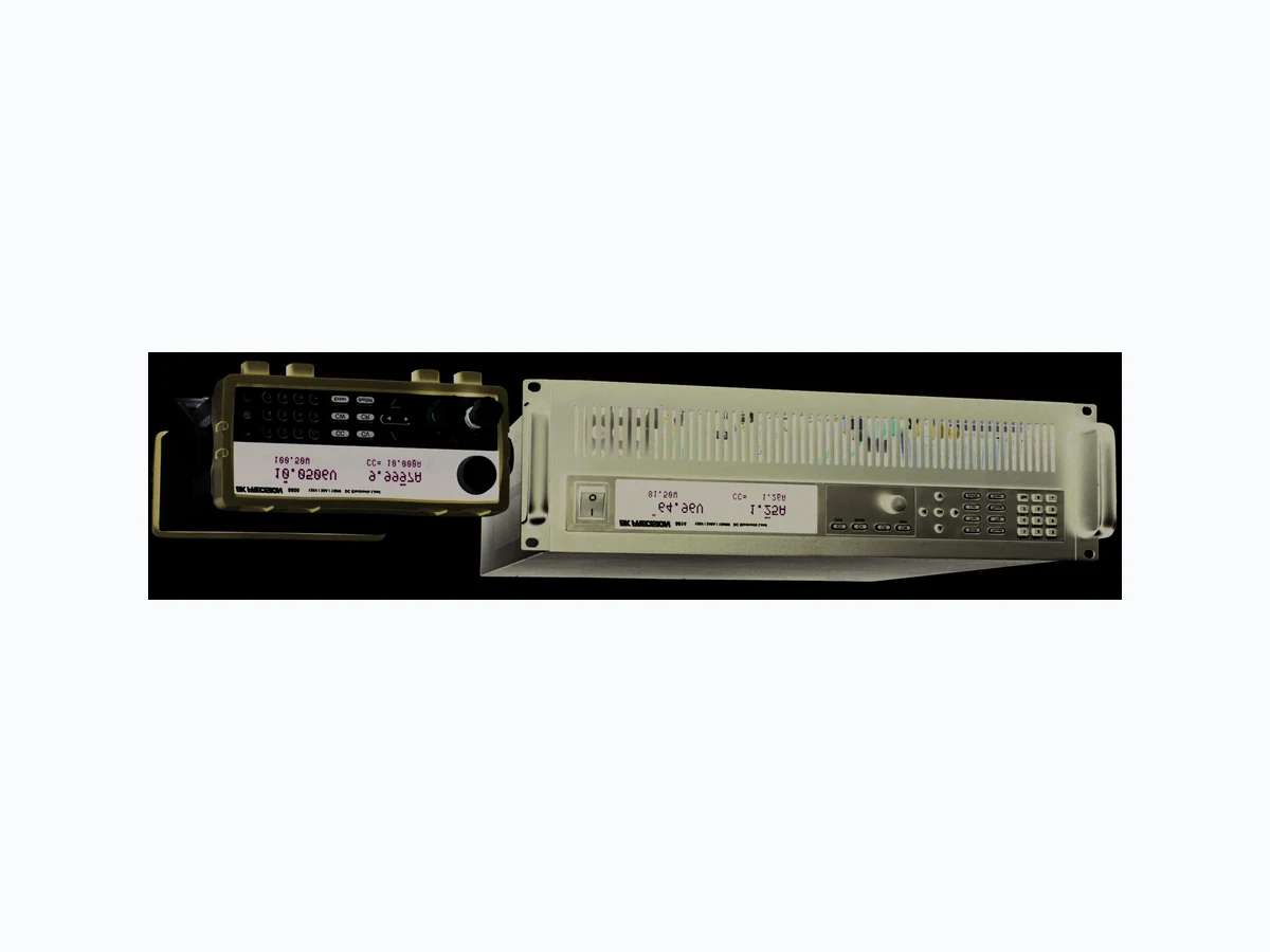
8600 ETC2
Document overview
- Manufacturer or author: Provided By www.digicamel.com(FREE DATASHEET DOWNLOAD SITE)
- PDF pages: 7
Technical content
Features
I Voltage range up to 500 V I Current range up to 24 0 A I CC/CV/CR/CW operating m odes I 1 6 -bit voltage and current m easurem ent system providing 1 m V / 0.1 m A resolution I Transient m ode up to 25 kH z in CC m ode I List m ode function I Store and recall up to 1 00 setups I A djustable slew rate in CC m ode I Flexible triggering options via front panel, external input, tim er, or bus I B uilt-in battery test function with voltage level, capacity level, and tim er stop conditions I T est m odes to validate the O CP/O PP protection functions of a power supply I CR-LED m ode to sim ulate the loading behavior of typical LED s I Rem ote sense I A nalog current control and m onitoring I Therm ostatically controlled fan I Standard U SB (U SB TM C-com pliant), RS23 2, and GPIB interfaces supporting SCPI com m ands for rem ote control I O VP/O CP/O PP/O TP including local and rem ote reverse voltage (LRV/RRV) protection I Com pact 1 9” half-rack form factor allows for side-by-side rack m ounting of two units (m odels 86 00, 86 01 and 86 02) M odel 8600 8601 8602 8610 8612 8614 8616 Power 1 50 W 250 W 200 W 750 W 750 W 1 500 W 1 200 W O perating Voltage 0 – 1 20 V 0 – 1 20 V 0 – 500 V 0 – 1 20 V 0 – 500 V 0 – 1 20 V 0 – 500 V Rated Current 0 – 3 0 A 0 – 6 0 A 0 – 1 5 A 0 – 1 20 A 0 – 3 0 A 0 – 24 0 A 0 – 6 0 A areas for quick system recall. A ll load param eters such as voltage, current, slew rate, and width can be set via the front panel or program m ed rem otely. The 86 00 Series provides standard U SB (U SB TM C-com pliant), GPIB , or RS-23 2 serial interfaces for rem ote com m unication. T o ensure the reliability of your testing, the 86 00 Series provides a power-on system self-test and num erous protection features: overtem perature (O TP), overvoltage (O VP), overcurrent (O CP), overpower (O PP), and local/rem ote reverse voltage (LRV/RRV) protection. Special A pplications The 86 00 Series provides a built-in battery test m ode to m easure the am pere-hour (A h) characteristic of a battery and a unique CR-LED m ode to sim ulate the loading behavior of a typical LED .
w w w .bkprecision.com Program m able D C Electronic Loads
8600 Series
M odels 8600, 8601 & 8602 Bright dual-line display The 86 00 Series display shows both m easured input values and set param eters sim ultaneously. Front panel Rear panel Rotary control knob Cooling fan RS-2 32 interface U SB interface G PIB interface Current m onitor BN C output O utputs a 0-1 0 V signal that follows 0-full range of the input current. I/O term inal block External trigger, external analog program m ing, external input O n/O ff control, voltage fault pin, and rem ote sense term inals Line voltage selector N um eric keypad Function keys Cursor keys Load input term inal Intuitive user interface The num eric keys and rotary knob provide a convenient interface for setting the operating m ode and desired current, voltage, and resistance levels quickly and precisely. H igh current test lead accessory m odel TLPW R1
w w w .bkprecision.com Program m able D C Electronic Loads M odels 8610, 8612, 8614 & 8616 N um eric keypad Function keys Cursor keys Bright dual-line display The 86 00 Series display shows both m easured input values and set param eters sim ultaneously. Pow er sw itch O perating m ode keys Cooling fan I/O term inal block External trigger, external analog program m ing, external input O n/O ff control, voltage fault pin, and rem ote sense term inals Input fuse holder A C line input Current m onitor BN C output O utputs a 0-1 0 V signal that follows 0-full range of the input current. Input term inals Front panel Rear panel
w w w .bkprecision.com Program m able D C Electronic Loads The 86 00 Series can execute m ultiple test sequences in autom atic test m ode. U p to 1 00 different sequences can be linked to run steps of various operating m odes and loading conditions. Each sequence can also be program m ed with upper and lower lim it Pass/Fail criteria. W hen applied in production testing, you can easily judge whether the test param eters of your devices are within the specification lim its and adjust your process according to the Pass/Fail verdict. List m ode N ot lim ited to just switching between two levels, list m ode lets you generate m ore com plex sequences of input changes with several different levels. U p to 7 groups of list files can be saved and executed in CC m ode via internal or external trigger. Each list can contain up to 84 steps with varying slew rates and a m inim um width tim e of 20 μs per step. CR-LED m ode U se the load’s unique CR-LED operating m ode to test LED drivers. This function allows users to configure the LED ’s operating resistance and forward voltage to sim ulate the loading behavior of typical LED s. Low voltage operation The 86 00 Series can operate at low voltages for applications such as fuel cell and solar cell testing. Vd = Forward voltage of the LED Rd = LED operating resistance Vo = LED operating voltage Io = LED operating current Voltage (V ) Current (A ) 123450 Typical m inim um operating voltage at full scale current 8600 8601 8602 8610 8612 8614 8616 86 1 4 86 1 0 86 02 86 01 86 1 6 86 00 86 1 2 I V LED I-V Curve Transient operation enables the load to periodically switch between two load levels (A /B ). A power supply’s regulation and transient characteristic can be evaluated by m onitoring the supply’s output voltage under varying com binations of load levels, duty cycle, and slew rate. The 86 00 Series can sim ulate these conditions in CC, CV , CW , and CR m ode. Transient operation A level Trigger 01 2 3 4 5 6 7 8 Steps t A Slew Rate B level A t I V CC 1 A 1 s 0.5 s 1 .5 s 2.5 s CV 3 V Io Vd Vo Rd CW 0.5 W CR 2 Ω pass pass pass fail 24 0 1 20 6 0 3 0
w w w .bkprecision.com Program m able D C Electronic Loads Pow erful com m unication interfaces The 86 00 Series provides standard GPIB , U SB , and RS23 2 interfaces for rem ote com m unication. These interfaces offer SCPI and U SB TM C standard com m unication protocols to control your electronic load from a PC. PC software is provided for front panel em ulation, generating and executing test sequences, or logging m easurem ent data without the need to write source code. A dditionally, this application software integrates with N I D ata D ashboard for LabVIEW apps, which allows users to create a custom dashboard on a tablet com puter or sm artphone to rem otely m onitor 86 00 Series D C loads via this PC software. I Rem ote m onitoring on iO S, A ndroid or W indows 8 com patible tablets or sm artphones via N I D ata D ashboard for LabVIEW apps I Log voltage, current, and power values with tim estam p I Run transient operation and list m ode program s rem otely I Create an unlim ited num ber of external list files to be executed from PC m em ory A pplication softw are In addition to front panel and rem ote interface control, current values can also be program m ed with an analog control signal. The electronic loads can be externally controlled from zero to full scale with a 0-1 0 V input signal. A B N C output is available on the rear for m onitoring the current with a 0-1 0 V output signal. External analog program m ing and m onitoring interface Control the input turn on state for the D C electronic load by configuring the Von latch function. This can be used to start and stop discharging of a battery or other power source at a specified voltage level. Voltage-on (Von) latch operation Battery test function The built-in battery test function uses CC m ode to calculate the battery capacity using a fixed current load discharge. U sers can specify cut-off voltage level, capacity level, and tim e stop conditions. A djustable slew rate In CC m ode, users can control the rate or slope of the change in current in a transient response test. Set the slew rate to as slow as 0.001 A /m s or as fast as 2.5 A /µs depending on the m odel and selected current range. t V t A Von Level Load Sink Current t A Slew Rate Rise Rate A /µs Rem ote control and program m ing Typical battery discharge curve H ours Volts 0.4 1 .8 1 .6 1 .4 1 .2 1 .0 0.8 0.6 The 86 00 Series can m easure the rise or fall tim e from a specified start and stop voltage level of the m easured input without the need for an oscilloscope. This function can also be used as an internal tim er to count how long the input has been enabled. Built-in rise and fall tim e m easurem ent O scilloscope display 86 00 Series display
w w w .bkprecision.com Program m able D C Electronic Loads M odel 8600 8601 8602 8610 8612 8614 8616 Input ratings Input voltage 0 – 1 20 V 0 – 1 20 V 0 – 500 V 0 – 1 20 V 0 – 500 V 0 – 1 20 V 0 – 500 V Input current Low 0 – 3 A 0 – 6 A 0 – 3 A 0 – 1 2 A 0 – 3 A 0 – 24 A 0 –6 A H igh 0 – 3 0 A 0 – 6 0 A 0 – 1 5 A 0 – 1 20 A 0 – 3 0 A 0 – 24 0 A 0 –6 0 A Input power 1 50 W 250 W 200 W 750 W 1 500 W 1 200 W M inim um operating voltage CV m ode Range Low 0 – 1 8 V 0 – 50 V 0 – 1 8 V 0 – 50 V 0 – 1 8 V 0 – 50 V H igh 0 – 1 20 V 0 – 500 V 0 – 1 20 V 0 – 500 V 0 – 1 20 V 0 – 500 V Resolution Low 0.1 m V 1 m V 0.1 m V 1 m V 0.1 m V 1 m V H igh 1 m V 1 0 m V 1 m V 1 0 m V 1 m V 1 0 m V A ccuracy Low ± (0.05% + 0.02% FS) ± (0.025% + 0.05% FS) ± (0.05% + 0.025% FS) ± (0.025% + 0.05% FS) H igh ± (0.05% + 0.025% FS) ± (0.025% + 0.05% FS) ± (0.05% + CC m ode Range Low 0 – 3 A 0 – 6 A 0 – 3 A 0 – 1 2 A 0 – 3 A 0 – 24 A 0 – 6 A H igh 0 – 3 0 A 0 – 6 0 A 0 – 1 5 A 0 – 1 20 A 0 – 3 0 A 0 – 24 0 A 0 – 6 0 A Resolution Low 0.01 m A 0.1 m A 1 m A 0.1 m A 1 m A 0.1 m A H igh 0.1 m A 1 m A 1 0 m A 1 m A 1 0 m A 1 m A A ccuracy CR m ode Range H igh 1 0 Ω - 7.5 kΩ Resolution 1 6 bit A ccuracy Low 0.01 % + 0.08 S H igh 0.01 % + 0.0008 S CW m ode Range 1 50 W 250 W 200 W 750 W 1 500 W 1 200 W Resolution 1 0 m W 1 00 m W Transient m ode (CC m ode) T1 & T2 (1 ) 20 µs – 3 6 00 s / Resolution: 1 0 µs A ccuracy 5 µs + 1 00 ppm Slew Rate (2) (1 ) Fast pulse trains with large transitions m ay not be achievable. (2) The slew rate specifications are not warranted, but are descriptions of typical perform ance. The actual transition tim e is defined as the tim e for the input to change from 1 0% to 90% , or vice versa, of the program m ed current values. In case of very large load changes, e.g. from no load to full load, the actual transition tim e will be larger than the expected tim e. The load will autom atically adjust the slew rate to fit within the range (high or low) that is closest to the program m ed value.
w w w .bkprecision.com Program m able D C Electronic Loads M odel 8600 8601 8602 8610 8612 8614 8616 Readback voltage Range Low 0 – 1 8 V 0 – 1 8 V 0 – 50 V 0 – 1 8 V 0 – 50 V 0 – 1 8 V 0 – 50 V H igh 0 – 1 20 V 0 – 1 20 V 0 – 500 V 0 – 1 20 V 0 – 500 V 0 – 1 20 V 0 – 500 V Resolution Low 0.1 m V 1 m V 0.1 m V 1 m V 0.1 m V 1 m V H igh 1 m V 1 0 m V 1 m V 1 0 m V 1 m V 1 0 m V A ccuracy ± (0.05% + 0.05% FS) Readback current Range Low 0 – 3 A 0 – 6 A 0 – 3 A 0 – 1 2 A 0 – 3 A 0 – 24 A 0 – 6 A H igh 0 – 3 0 A 0 – 6 0 A 0 – 1 5 A 0 – 1 20 A 0 – 3 0 A 0 – 24 0 A 0 – 6 0 A Resolution H igh 0.1 m A 1 m A 0.1 m A 1 0 m A 1 m A 1 0 m A 1 m A A ccuracy ± (0.05% + 0.05% FS) ± (0.05% + 0.1 % FS) ± (0.05% + 0.05% FS) ± (0.05% + 0.1 % FS) ± (0.05% + 0.05% FS) ± (0.05% + 0.1 % FS) ± (0.05% + 0.05% FS) Readback pow er Range 1 50 W 250 W 200 W 750 W 1 500 W 1 200 W Resolution 1 0 m W 1 00 m W Protection range (typical) O PP □1 50 W □250 W □200 W 76 0 W 1 550 W 1 250 W O CP H igh □3 3 A □6 6 A □1 6 .5 A 1 3 2 A 3 3 A 26 4 A 6 6 A O VP □1 20 V □1 20 V □500 V 1 3 0 V 53 0 V 1 3 0 V 53 0 V O TP 1 85 ºF□(85 °C) G eneral (typical) Short circuit Current (CC) Low 3 A 6 A 3 A 1 2 A 3 A 24 A 6 A H igh 3 0 A 6 0 A 1 5 A 1 20 A 3 0 A 24 0 A 6 0 A Voltage (CV) 0 V Resistance (CR) □3 5 m Ω □3 0 m Ω □3 00 m Ω 1 0 m Ω 1 20 m Ω 6 m Ω 6 0 m Ω Input term inal im pedance 1 50 k Ω 3 00 kΩ 1 M Ω 3 00 kΩ 1 M Ω 3 00 kΩ 1 M Ω A C input 1 1 0 V/220 V ± 1 0% , 50/6 0 H z O perating tem perature 3 2 ºF to 1 04 ºF (0 °C to 4 0 °C) Storage tem perature 1 4 ºF to 1 4 0 ºF (-1 0 °C to 6 0 °C) H um idity Indoor use, ≤ 95% Safety EN 6 1 01 0-1 :2001 , EU Low Voltage D irective 2006 /95/EC Electrom agnetic com patibility M eets EM C D irective 2004 /1 08/EC, EN 6 1 000-3 -2:2006 , EN 6 1 000-3 -3 :1 995+ A 1 :2001 + A 2:2005 W eight 9.9 lbs (4 .5 kg) 54 lbs (24 .6 kg) Three-Year W arranty Standard accessories U ser m anual, power cord, certificate of calibration & test report O ptional accessories TLPW R1 high current test leads, IT-E1 51 rackm ount kit (m odels 86 00, 86 01 , and 86 02 only) v102615