
DATASHEET SEARCH SITE
Document overview
- Manufacturer or author: Provided By www.digicamel.com(FREE DATASHEET DOWNLOAD SITE)
- PDF pages: 18
Technical content
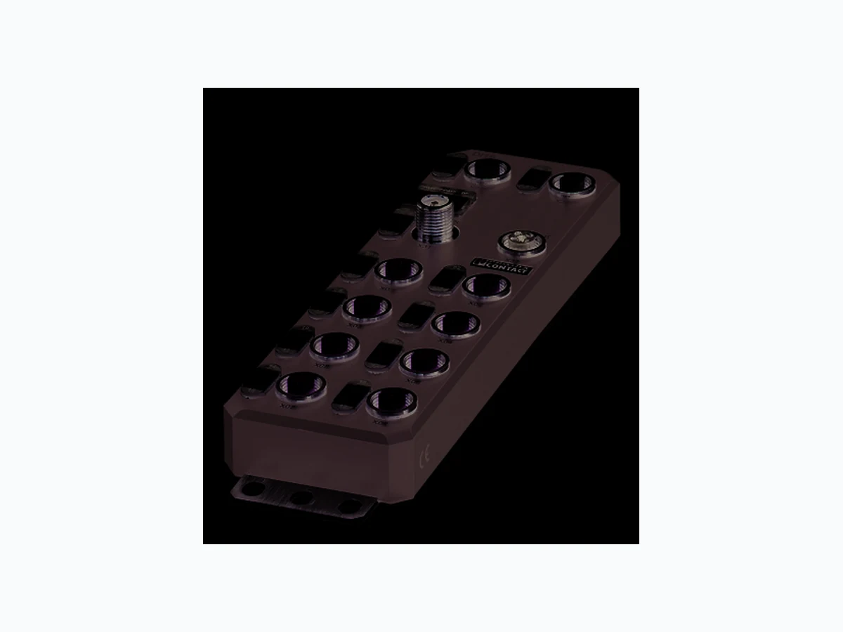
Axioline E Ethernet device, plastic housing, 16 inputs, 24 V DC, M12 fast connection technology AXL E ETH DI16 M12 6P © PHOENIX CONTACT Data sheet The Axioline E device is designed for use within an Ethernet network (Modbus/TCP). It is used to acquire digital signals. Ethernet features – 2 Ethernet ports (wit h integrated switch) – Supported protocols: SNMP v1, HTTP, TFTP, FTP, BootP, DHCP – Specification: Modbus application protocol V1.1b –F i r m w a r e c a n b e u p d a t e d – Integrated web server for web-based management Axioline E features – Connection to Ethernet network (Modbus/TCP) using M12 connectors (D-coded) – Transmission speed of 10 Mbps and 100 Mbps – Connection of digital sensors using M12 connectors (A-coded) – Diagnostic and status indicators – Short-circuit and overload protection of the sensor supply – IP65/67 degree of protection This data sheet is only valid in association with the associated user manual. Make sure you always use the latest documentation. It can be downloaded from the product at phoenixcontact.net/products. 8551_en_03 2016-02-08
8551_en_03 PHOENIX CONTACT 2 2T a b l e o f c o n t e n t s
8551_en_03 PHOENIX CONTACT 3 Description Ty pe Order No. Pcs./Pkt. Axioline E-Ethernet device in a plastic housing with 16 digital inputs,
24 V DC, M12 fast connection technology
AXL E ETH DI16 M12 6P 2701533 1 Accessories Ty pe Order No. Pcs./Pkt. An M12 screw plug for the unoccupied M12 sockets of the sensor/actuator cable, boxes and flush-type connectors (Protection and sealing elements) PROT-M12 1680539 5 Snap-in markers, Sheet, white, unlabeled, can be labeled with: THERMOMARK CARD, BLUEMARK CLED, BLUEMARK LED, TOPMARK LASER, Mounting type: snapped into marker carrier, Lettering field: 7 x 10 mm (Marking) UCT-EM (7X10) 0830765 10 Documentation Ty pe Order No. Pcs. / Pkt. User manual, English, Axioline E: system and installation UM EN AXL E SYS INST - - Application note, English: Updating the firmware of AXL E devices using the Windows Explorer AH EN FIRMWARE UPDATE AXL E - - Application note, English: Startup of Axioline E Ethernet devices (Modbus/TCP) using the ModScan32 Modbus master tool AH EN AXL E ETH MODSCAN32 - - Additional ordering data For additional accessories, visit phoenixcontact.net/products. 3O r d e r i n g d a t a
8551_en_03 PHOENIX CONTACT 4 Dimensions (nominal sizes in mm) Width 60 mm Height 185 mm Depth 30.5 mm Note on dimensions The height is 212 mm including fixing clips. General data Housing material Pocan ® Color anthracite Weight 480 g Ambient temperature (operation) -25 °C ... 60 °C CAUTION: Risk of burns If the device is used at an ambient temperature above 50°C, the contact temperature of metal surfaces may exceed 70°C. Ambient temperature (storage/transport) -25 °C ... 85 °C Permissible humidity (operation) 5 % ... 95 % Permissible humidity (storage/transport) 5 % ... 95 % Air pressure (operation) 70 kPa ... 106 kPa (up to 3000 m above sea level) Air pressure (storage/transport) 70 kPa ... 106 kPa (up to 3000 m above sea level) Degree of protection IP65/IP67 Protection class III, IEC 61140, EN 61140, VDE 0140-1 Connection data Connection method M12 connector Interface Ethernet Connection method M12 connectors, D-coded Designation connection point Copper cable Number of positions 4 Transmission speed 10/100 MBit/s (with auto negotiation) Cycle Time min. 1 ms
4 Technical data
30,5 198,5 60 30
8551_en_03 PHOENIX CONTACT 5 Modbus/TCP Equipment type Modbus slave (server) Modbus protocols Modbus/TCP Additional protocols SNMP v1, HTTP, TFTP, FTP, BootP, DHCP Specification Modbus application protocol V1.1b Supply: Module electronics and sensors (US) Connection method M12 connector (T-coded) Number of positions 4 Supply voltage 24 V DC Nominal supply voltage range 18 V DC ... 31.2 V DC (including all tolerances, including ripple) Typical current consumption 1 90 mA ±15 % (at 24 V DC) Current consumption max. 12 A Supply: Actuators (UA) for additional devices Connection method M12 connector (T-coded) Number of positions 4 Supply voltage 24 V DC Nominal supply voltage range 18 V DC ... 31.2 V DC (including all tolerances, including ripple) Typical current consumption 3 mA ±15 % (at 24 V DC) Current consumption max. 12 A Digital inputs Number of inputs 16 (EN 61131-2 types 1 and 3) Connection method M12 connector, double occupancy Connection method 2, 3, 4-wire Nominal input voltage 24 V DC Nominal input current typ. 3 mA Sensor current per channel typ. 0.75 mA (from Us) Total sensor current max. 1.2 A (per device) Input voltage range "0" signal -30 V DC ... 5 V DC Input voltage range "1" signal 11 V DC ... 30 V DC Input filter time < 1000 µs Permissible conductor length to the sensor 30 m Overload protection, short-circuit protection of sensor supply Yes
8551_en_03 PHOENIX CONTACT 6 Electrical isolation/isolation of the voltage areas Test section Tes t volta ge
24 V supply (communications power and sensor supply, digital inputs)/
bus connection (Ethernet 1)
500 V AC, 50 Hz, 1 min
bus connection (Ethernet 2)
24 V supply (communications power and sensor supply, digital inputs)/FE 500 V AC, 50 Hz, 1 min
Bus connection (Ethernet 1)/FE 500 V AC, 50 Hz, 1 min Bus connection (Ethernet 2)/FE 500 V AC, 50 Hz, 1 min Bus connection (Ethernet 1)/bus connection (Ethernet 2) 500 V AC, 50 Hz, 1 min
24 V supply (actuator supply)/
24 V supply (communications power and sensor supply, digital inputs)
24 V supply (actuator supply)/bus connection (Ethernet 1) 500 V AC, 50 Hz, 1 min
24 V supply (actuator supply)/bus connection (Ethernet 2) 500 V AC, 50 Hz, 1 min
24 V supply (actuator supply)/FE 500 V AC, 50 Hz, 1 min
Vibration resistance in acc. with EN 60068-2-6/IEC 60068-2-6 5g Shock in acc. with EN 60068-2-27/IEC 60068-2-27 30g, 11 ms period, half-sine shock pulse Continuous shock according to EN 60068-2-27/IEC 60068-2-27 10g Conformance with EMC Directive 2004/108/EC Noise immunity test in accordance with EN 61000-6-2 Electrostatic discharge (ESD) EN 61000-4-2/IEC 61000-4-2 Criterion B; 6 kV contact discharge, 8 kV air discharge Electromagnetic fields EN 61000-4-3/IEC 61000-4-3 Criterion A; Field intensity: 10 V/m Fast transients (burst) EN 61000-4-4/IEC 61000-4-4 Criterion B, 2 kV Transient surge voltage (surge) EN 61000-4-5/IEC 61000-4-5 Criterion B; DC supply lines: ±0 .5 kV/±0.5 kV (symmetrical/asymmetrical) Conducted interference EN 61000-4-6/IEC 61000-4-6 Criterion A; Test voltage 10 V Noise emission test as per EN 61000-6-4 Radio interference properties EN 55022 Class A Approvals For the latest approvals, please visit phoenixcontact.net/products.
8551_en_03 PHOENIX CONTACT 7
5 Internal circuit diagram
Figure 1 Internal wiring of connections Key: Key: Green area: Network Blue area: U S Yellow area: U A X31 X32 X01 X02 X03 X04 X05 X06 X07 X08 2 2 2 2 24 V 3.3 V µC U OUTS U OUTA UI NS UI NA X21 X22 ETH1 ETH2 Transmitter with electrical isolation Power supply unit with electrical isolation Microcontroller Digital input LED µC
8551_en_03 PHOENIX CONTACT 8
6 Pin assignment
6.1 Ethernet and power supply connection
Figure 2 Connections for Ethernet and voltage supply
6.2 Ethernet pin assignment
Figure 3 Ethernet pin assignment, D-coded
6.3 Pin assignment of the power supply U S/UA
Figure 4 Pin assignment of the power supply, T-coded Designation Meaning Port 1 (X21) Ethernet port 1 Port 2 (X22) Ethernet port 2 US IN (X31) Power supply IN (logic and sensors) UA IN (X31) Power Supply IN (actuators) for additional devices US OUT (X32) Power supply OUT for additional devices UA OUT (X32) Power supply OUT for additional devices Ground the device by means of the mounting screws. Port 1 Port 2 Pin Ethernet port 1 (X21) Ethernet port 2 (X22) 1T X + T X + 2R X + R X + 3T X - T X - 4R X - R X - The shield is connected to FE in the device. The thread is used for additional shielding.Pin IN OUT Conductor colors 1+ 2 4 V D C ( U S) +24 V DC (U S)B r o w n 2G N D ( U A)G N D ( U A)W h i t e 3G N D ( U S)G N D ( U S)B l u e 4+ 2 4 V D C ( U A) +24 V DC (U A)B l a c k 1 2 X21 2 3 X22 X32X31 1 4 3 2
8551_en_03 PHOENIX CONTACT 9
6.4 Input connection
Figure 5 Input connections
6.5 Pin assignment of the inputs
Figure 6 Pin assignment of the inputs, A-coded Designation Meaning Pin Input socket 1 +24 V DC (U S) 3G N D 5F E X01, X03, X05, X07 X02, X04, X06, X08 2 3
8551_en_03 PHOENIX CONTACT 10
7 Connection example
Figure 7 Typical connection of sensors
8 Connection notes
+24 V IN 5 IN 12 +24 V IN 11 Note: data corruption or loss Implement the FE connection using mounting screws, in order to ensure immunity to inter- ference. NOTE: device damage To ensure IP65/IP67 protection, cover unused sockets with protective caps. NOTE: Damage to the electronics Only supply the sensors with the voltage U S provided at the terminal points. NOTE: Damage to the electronics Observe the correct polarity of the supply volt- ages US and UA in order to prevent damage to the device. NOTE: Malfunction When connecting the sensors, observe the assignment of the connections to the Ethernet input data. Secure the device to a level surface or to a profile. Do not use this device to bridge gaps, in order to prevent forces being transmitted via the device. Use standard M5 screws with toothed lock washer and self-locking nuts. Observe the maximum torque of the screws.
8551_en_03 PHOENIX CONTACT 11
9 Configuration via rotary encoding switch
You can configure the address assignment and other func- tions using rotary encoding switches. After modifying the switch position, restart the device, as the modification to the switch position does not take effect during operation. Figure 8 Rotary encoding switch The code results from the sum of S1 x 10 plus S2 x 1. The image shows code 77 (7 x 10 + 7).
9.1 Remote access
At this switch position, it is possible to remotely configure the device using corresponding tools (e.g., Startup+, web- based management (WBM)). Behavior during initial startup, after resetting the IP pa- rameters or after resetting to default settings Default: BootP aktiviert, DHCP deaktiviert A valid IP address is not assigned (0.0.0.0) and communica- tion is therefore not possible. The device transmits continuous BootP requests, until a valid IP address has been received. Valid IP parameters are then automatically saved as config- uration data on the device. Each additional startup BootP activated BootP requests are transmitted even in the case of a valid configuration. If the device receives a BootP reply, the new IP parameters are applied. Otherwise the device starts with the last valid configuration. DHCP activated For behavior, see switch position 51 ... 159. The station name can be selected in WBM, the default station name is the MAC address with "-" used as the separator. Static (BootP and DHCP deactivated) The device starts with the last valid assigned IP configura- tion.
9.2 Manual address assignment
Switch position 01 ... 50 Default: BootP deactivated, DHCP activated The first three octets in the IP address are preset as 192.168.0.x. The subnet mask is 255.255.255.0. Specify the last byte with the switch position. As such, you can select IP addresses between 192.168.0.1 and 192.168.0.50. Prior to transferring the IP address, a test is performed to check for any potential IP address conflicts. If a conflict is detected, the device temporarily switches the IP address to 0.0.0.0 (no IP communication). In this case, the NET LED flashes red. Eliminate the conflict and restart the device.
9.3 DHCP name assignment
Switch position 51 ... 159 This switch position is used to easily specify the DHCP host name for the device. The host name is provided to the DHCP server via DHCP options. This is therefore able to send a DNS update to the DNS server. The DNS name consists of one set part, which is based on the order designation, and a variable part, which is deter- mined by the switch position. The first part of the station name is AXL-E-ETH-. The set number is added. This results in the following station names: AXL-E-ETH-051 ... AXL-E-ETH-159. S1 S2 Code Function 0 0 00 Remote access (default)
0 A 0A Static address
0 E 0E Resetting IP parameters
0 F 0F Resetting to the
B C D E F x10 810 x10
8551_en_03 PHOENIX CONTACT 12 Behavior during initial startup, after resetting the IP pa- rameters or after resetting to default settings A valid IP address is not assigned (0.0.0.0) and communica- tion is therefore not possible. The device transmits continuous DHCP discover messages until a valid IP address has been received. Each additional startup The device transmits continuous DHCP requests. There are two possible scenarios: 1. The DHCP server assigns a new IP address. The device applies the new IP parameters. 2. The DHCP server does not respond. The device transmits continuous DHCP Discover messages until new IP parameters have been received.
9.4 Static address
Behavior during initial startup, after resetting the IP pa- rameters or after resetting to default settings A valid IP address is not assigned (0.0.0.0) and communica- tion is therefore not possible. Assign an address initially with another switch position. Each additional startup After a voltage reset, the device maintains the IP address which was assigned last.
9.5 Resetting IP parameters
The IP parameters stored on the device are reset. All other settings made on the device are retained. – BootP is activated for switch position 00. – IP address, subnet mask: 0.0.0.0 As long as the switch position 0E remains selected, no con- nection to the device can be established. IP communication is deactivated (LED NET static yellow).
9.6 Resetting to the default settings
All settings are reset to default settings, including IP param- eters.
9.7 Reserved/invalid switch position
The device starts with the previous settings, e.g., with the settings that were valid before the device was restarted. An invalid switch position is indicated by the RDY LED (red on). With this switch position, modifying the IP ad- dress via tools or web-based management is not possible. The device is ready for operation after power- ing up, as soon as the RDY LED lights up green. A connection to the device however cannot be established in this switch position. As soon as the RDY LED lights up green, a new switch position can be selected on the ro- tary encoding switch and the device can be restarted.
8551_en_03 PHOENIX CONTACT 13
10 Local status and diagnostic indicators
10.1 Indicators for Ethernet ports and power supply
Figure 9 Indicators for Ethernet ports and power supply Designation Color Mean- ing State Description LNK 1/2 Green Link Green ON Connection pr esent at port 1/2. OFF Connection not present at port 1/2. ACT 1/2 Yellow Activity Yellow ON Data transmission present at port 1/2. OFF Data transmission not present at port 1/2. RDY Green/ yellow/ red Ready Green ON Device is ready for operation. Green flashing Firmware up date is being performed. Flashing green/ yellow Over- or undervoltage at US Temperature of the device is in the critical area. And red US LED: sensor supply overload Red ON Rotary encoding sw itches are set to an invalid/reserved position. OFF Device is not ready for operation. NET Green/ yellow/ red Network status Green flashing A connection can be established to the device. Green ON At least one connection ha s been established to the device. Yellow flashing BootP request or DHCP requests/discover messages are being transmitted. Yellow ON The IP configuration/IP address (0.0.0.0) is invalid. Red flashing An IP address conflict has occu rred during static configuration via ro- tary coding switches (IP address assigned twice). Red ON A network error has occurred. The monitoring function detected an error or the process data watchdog was activated. OFF Device is not ready for operation. US Green/ red U Sensorik Green ON Communications powe r/sensor voltage present OFF Communications power/sensor voltage not present or too low. Red ON Sensor voltage overload UA Green U Aktorik ON Actuator voltage present. OFF Actuator voltage not present.
8551_en_03 PHOENIX CONTACT 14
10.2 Input indicators
Figure 10 LEDs of the inputs Designation Color Meaning State Description 00 ... 07, 10 ... 17 Yellow Status of the inputs ON Input is set. OFF Input is not set. The numbering of the LEDs is as follows: the first number specifies the byte, the second number specifies the bit.
8551_en_03 PHOENIX CONTACT 15
11 Modbus protocols and registers
The device supports a Modbus/TCP server. As such, the Modbus protocol can be used in a connection- related (TCP) manner.
11.1 Modbus connections
The device supports up to eight Modbus/TCP connections at the same time. The connection can access different addresses simultane- ously. Since eight connections are supported, a connection can quickly be restored. This means that the client can success- fully restore an interrupted Modbus connection.
11.2 Modbus conformity classes
The device supports Modbus conformity classes 0 and parts of classes 1 and 2.
11.3 Modbus function codes
The following function codes are supported:
11.4 Modbus register
FC1 Read coils Read output and input bits FC2 Read input discretes Read multiple input bits FC3 Read holding registers Read words from outputs and inputs FC4 Read input registers Read words from inputs FC5 Write coil Write an output bit FC6 Write single registers Write word for output data FC15 Write multiple coils Write multiple output bits FC16 Write multiple registers Write several output words FC23 Read/write mul- tiple registers Read and write several pro- cess data for inputs and out- puts Modbus register (16-bit word) Access Function Access with function code Special register
2006 W Command register FC6, FC16, FC23
7996 R Status register FC3, FC4, FC23
7997 R Diagnostic status register FC3, FC4, FC23
8000 R Input process data FC1, FC2, FC3, FC4, FC23
In write access to the Modbus/TCP clients on the “Read only” register, the data is not transferred and is an- swered with exception code 02.
8551_en_03 PHOENIX CONTACT 16
11.5 Command register (2006)
Only set one bit for the command register, otherwise an error message is output. Only write access is enabled for the reg- ister.
11.6 Status register (7996)
11.7 Diagnostic status register (7997)
(hex) Meaning 0 0001 Reserved 1 0002 Reserved 2 0004 Reserved 3 0008 Reserved 4 0010 Reserved 5 0020 Reserved 6 0040 Reserved 7 0080 Delete a detected I/O warning/malfunction 8 0100 Reserved 9 0200 Reserved 10 0400 Reserved 11 0800 Reserved 12 1000 Reserved 13 2000 Reserved 14 4000 Reserved 15 8000 Reserved Bit Code (hex) Meaning 0 0001 1 An error occurred (e.g., a bit in the di- agnostic register is set). For addi- tional information, please refer to reg- ister 2004.
0 No error
(hex) Meaning 0 0001 Reserved 1 0002 Reserved 2 0004 Undervoltage of sensor supply 3 0008 Surge voltage of sensor supply 4 0010 Short circuit or overload of the sensor supply 5 0020 Reserved 6 0040 Reserved 7 0080 Reserved 8 0100 Reserved 9 0200 Reserved 10 0400 Overtemperature of the device 11 0800 Reserved 12 1000 Reserved 13 2000 Reserved 14 4000 Reserved 15 8000 Reserved
8551_en_03 PHOENIX CONTACT 17
11.8 Figure of process data on Modbus register 8000
Key:
12 Startup
12.1 Delivery state/ default settings
By default upon delivery, the following functions and fea- tures are available: IP settings Firmware update System identification Web-based Management (WBM)
12.2 Restoring the default settings
There are two options for resetting the default settings: – Via web-based management, go to the Administration web page > default settings and follow the instructions. – Via the rotary coding sw itch, switch position 0F
12.3 Starting the firmware
Once you have connected the power, the firmware is started. After completion of the firmware boot process, the NET LED either lights up or flashes green. Process data input word 8000 Byte Byte 0 Byte 1 B i t 7654321076543210 IN 07 06 05 04 03 02 01 00 17 16 15 14 13 12 11 10 Connection X04 X03 X02 X01 X08 X07 X06 X05 P i n 2424242424242424 DI 8 7 6 5 4 3 2 1 16 15 14 13 12 11 10 9 Bit: Process data assignment IN: LED marking DI: Device input IP parameters: 0.0.0.0 Subnet mask: 0.0.0.0 Default Gateway: 0.0.0.0 BootP: activated Firmware update on next re- start: deactivated TFTP server IP address: 192.168.210.211 Firmware file name: FIRMWARE.NXF Device name: No name assigned Description: No description assigned Device location: No location assigned Contact: No contact assigned User name: admin Password: private
8551_en_03 18PHOENIX CONTACT GmbH & Co. KG • 32823 Blomberg • Germany phoenixcontact.com
13 SNMP - Simple Network Manage-
The device supports SNMP v1. Management Information Base - MIB For the object descriptions, please refer to the ASN1 de- scriptions for this product. The password for read access is “public” and cannot be changed. By default upon delivery, the password for write/read access is “private” and can be modified at any time.
14 WBM - Web-based management
The device has a web server, which generates the required pages for web-based management and, depending on the requirements of the user, sends them to a standard web browser. Web-based management can be used to access static information (e.g., technical data, MAC address) or dy- namic information (e.g., IP address, status information). Calling web-based management The device web server can be addressed using the IP ad- dress if configured accordingly. The homepage (web page) of the device is accessed by entering the URL “http://ip-address”. Example: http://172.16.113.38 The default user name is “admin”, the default password is “private”.
15 Firmware update
In order to update the firmware of the device, the device must be provided with a firmware container via a TFTP server or it must be loaded onto the device via FTP. Any FTP client or TFTP server can be used for this. The update must always be initiated by the web-based management. When carrying out the firmware update, the RDY LED flashes yel- low.
16 Quick Connect
The device supports Quick Connect Class A. After switching on the mains voltage, it is ready to operate in under 350 ms in order to process a connection request. A cyclic process data connection can be established in under 500 ms.
17 Endianness
The Modbus specification stipulates Big Endian format; words (16-bit) are mapped 1:1. Individual bytes (modules with a process data width of 1 byte) are mapped to the lower byte (low byte) of a register. In the read direction, the upper byte (high byte) contains 00hex and is ignored in the write direction. The corresponding latest MIBs are available on the Internet at phoenixcontact.net/products. If you cannot access the WBM pages, check the connection settings in your browser and deactivate the proxy, if set.