
DATASHEET SEARCH SITE
Document overview
- Manufacturer or author: Provided By www.digicamel.com(FREE DATASHEET DOWNLOAD SITE)
- PDF pages: 25
Technical content
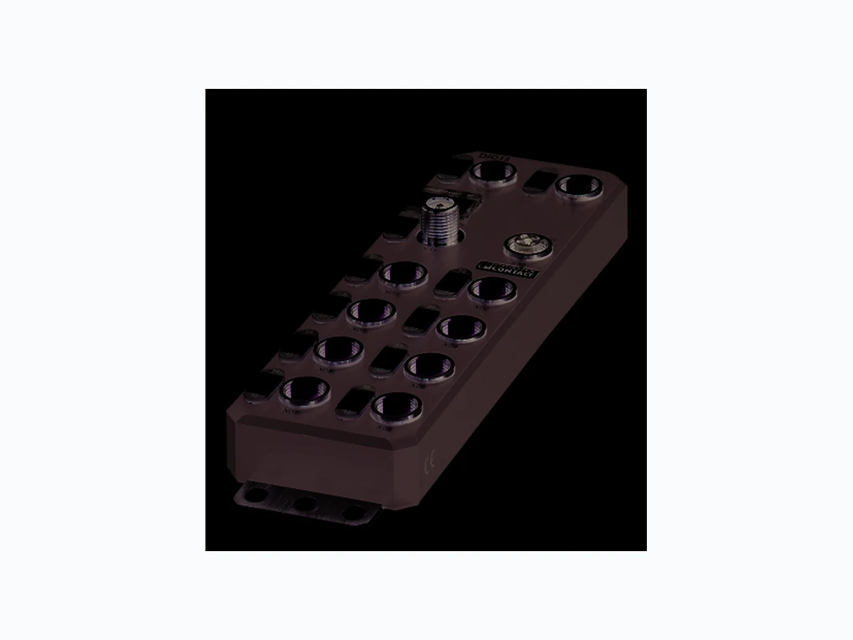
Axioline E EtherCAT® device, plastic housing, 16 freely configurable inputs or outputs, 24 V DC, M12 fast connection technology AXL E EC DIO16 M12 6P © PHOENIX CONTACT Data sheet The Axioline E device is designed for use within an EtherCAT® network. It is used to acquire and output digital signals. EtherCAT® is a registered trademark and patented technol- ogy, licensed by Beckhoff Auotmation GmbH, Germany. EtherCAT® features –2 E t h e r n e t - P o r t s – Automatic addressing – Identification: – Rotary coding switch for assigning the ID for the “Explicit Device ID” mechanism – Configured Second Station Alias –H o t C o n n e c t – Acyclic data communication (CoE and FoE mailbox protocols) – Supports the EtherCAT ® cycle time of min. 100 µs – Supports distributed clocks (jitter << 1 μs) – Specification: ETG.1000 V1.02 – Device description by means of ESI –F i r m w a r e c a n b e u p d a t e d Axioline E features – Connection to EtherCAT ® network using M12 connectors (D-coded) – Transmission speed 100 Mbps – Connection of digital sensors and actuators to M12 connectors (A-coded) – Diagnostic and status indicators – Short-circuit and overload protection of the sensor supply – IP65/67 degree of protection This data sheet is only valid in association with the associated user manual. Make sure you always use the latest documentation. It can be downloaded from the product at phoenixcontact.net/products. Abbreviations used – CoE: CAN application layer over EtherCAT ® – DC: distributed clocks – FoE: file access over EtherCAT ® 8542_en_03 2015-09-10
8542_en_03 PHOENIX CONTACT 2 2T a b l e o f c o n t e n t s
8542_en_03 PHOENIX CONTACT 3 Description Type Order No. Pcs. / Pkt. Axioline E-EtherCAT® device in a plastic housing with 16 freely configu- rable inputs or outputs, 24 V DC, M12 fast connection technology AXL E EC DIO16 M12 6P 2701522 1 Accessories Type Order No. Pcs. / Pkt. An M12 screw plug for the unoccupied M12 sockets of the sensor/actuator cable, boxes and flush-type connectors (Protection and sealing elements) PROT-M12 1680539 5 Snap-in markers, Sheet, white, unlabeled, can be labeled with: THERMOMARK CARD, BLUEMARK CLED, BLUEMARK LED, TOPMARK LASER, Mounting type: snapped into marker carrier, Lettering field: 7 x 10 mm (Marking) UCT-EM (7X10) 0830765 10 Documentation Type Order No. Pcs. / Pkt. User manual, English: Axioline E: system and installation UM EN AXL E SYS INST - - Application note, English: Updating the firmware of Axioline E-EtherCAT® devices with TwinCAT® AH EN FIRMWARE UPDATE AXL E EC - - Additional ordering data For additional accessories, visit phoenixcontact.net/products. 3O r d e r i n g d a t a
8542_en_03 PHOENIX CONTACT 4 Dimensions (nominal sizes in mm) Width 60 mm Height 185 mm Depth 30.5 mm Note on dimensions The height is 212 mm including fixing clips. General data Housing material Pocan ® Color anthracite Weight 480 g Ambient temperature (operation) -25 °C ... 60 °C CAUTION: Risk of burns If the device is used at an ambient temperature above 50°C, the contact temperature of metal surfaces may exceed 70°C. Ambient temperature (storage/transport) -25 °C ... 85 °C Permissible humidity (operation) 5 % ... 95 % Permissible humidity (storage/transport) 5 % ... 95 % Air pressure (operation) 70 kPa ... 106 kPa (up to 3000 m above sea level) Air pressure (storage/transport) 70 kPa ... 106 kPa (up to 3000 m above sea level) Degree of protection IP65/IP67 Protection class III, IEC 61140, EN 61140, VDE 0140-1 Connection data Connection method M12 connector Interface EtherCAT® Number 2 Connection method M12 connectors, D-coded Designation connection point Copper cable Number of positions 4 Transmission speed 100 MBit/s (with autonegotiation) Cycle Time < 100 µs
4 Technical data
30,5 198,5 60 30
8542_en_03 PHOENIX CONTACT 5 EtherCAT® Equipment type EtherCAT ® slave Mailbox protocols CANopen® over EtherCAT®, File access over EtherCAT® Type of addressing Auto-increment addressing Fixed position addressing Logical addressing Specification ETG.1000 V1.02 Supply: Module electronics, sensors and actuators (US) Connection method M12 connector (T-coded) Number of positions 4 Supply voltage 24 V DC Nominal supply voltage range 18 V DC ... 31.2 V DC (including all tolerances, including ripple) Typical current consumption 1 90 mA ±15 % (at 24 V DC) Current consumption max. 12 A Supply: Actuators (UA) for additional devices Connection method M12 connector (T-coded) Number of positions 4 Supply voltage 24 V DC Nominal supply voltage range 18 V DC ... 31.2 V DC (including all tolerances, including ripple) Typical current consumption 3 mA ±15 % (at 24 V DC) Current consumption max. 12 A Digital inputs Number of inputs 16 (EN 61131-2 types 1 and 3) Connection method M12 connector, double occupancy Connection method 2, 3, 4-wire Nominal input voltage 24 V DC Nominal input current typ. 3 mA Sensor current per channel typ. 0.75 mA (from US) Total sensor current max. 1.2 A (per device) Input voltage range "0" signal -30 V DC ... 5 V DC Input voltage range "1" signal 11 V DC ... 30 V DC Input filter time < 1000 µs Permissible conductor length to the sensor 30 m Overload protection, short-circuit protection of sensor supply Yes Digital outputs Number of outputs 16 Connection method M12 connector, double occupancy Connection method 2, 3-wire Nominal output voltage 24 V DC (from voltage US) Output voltage range 18 V DC ... 31.2 V DC Maximum output current per channel 0.5 A Nominal load, ohmic 12 W (48 Ω; with nominal voltage) Nominal load, inductive 12 VA (1.2 H; 48 Ω; with nominal voltage) Signal delay max. 150 µs (when switched on) Signal delay max. 200 µs (when switched off)
8542_en_03 PHOENIX CONTACT 6 Switching frequency max. 5500 per second (with at least 50 mA load current) Switching frequency max. 1 per second (with inductive load) Limitation of the voltage induced on circuit interruption -28 V ... -17 V Output voltage when switched off max. 1 V Output current when switched off max. 20 µA Behavior with overload Auto restart Reverse voltage resistance to short pulses Reverse voltage proof Overcurrent shut-down min. 0.7 A Overload protection, short-circuit protection of outputs Electronic Electrical isolation/isolation of the voltage areas Test section Test voltage
24 V supply (communications power/sensor supply, digital inputs/outputs)/
bus connection (Ethernet 1)
500 V AC, 50 Hz, 1 min
bus connection (Ethernet 2) Bus connection (Ethernet 1)/FE 500 V AC, 50 Hz, 1 min Bus connection (Ethernet 2)/FE 500 V AC, 50 Hz, 1 min Bus connection (Ethernet 1)/bus connection (Ethernet 2) 500 V AC, 50 Hz, 1 min
24 V supply (actuator supply)/24 V supply (communications power and
sensor supply, digital inputs/outputs)
24 V supply (actuator supply)/bus connection (Ethernet 1) 500 V AC, 50 Hz, 1 min
24 V supply (actuator supply)/bus connection (Ethernet 2) 500 V AC, 50 Hz, 1 min
24 V supply (actuator supply)/FE 500 V AC, 50 Hz, 1 min
Vibration resistance in acc. with EN 60068-2-6/IEC 60068-2-6 5g Shock in acc. with EN 60068-2-27/IEC 60068-2-27 30g, 11 ms period, half-sine shock pulse Continuous shock according to EN 60068-2-27/IEC 60068-2-27 10g Conformance with EMC Directive 2004/108/EC Noise immunity test in accordance with EN 61000-6-2 Electrostatic discharge (ESD) EN 61000-4-2/IEC 61000-4-2 Criterion B; 6 kV contact discharge, 8 kV air discharge Electromagnetic fields EN 61000-4-3/IEC 61000-4-3 Criterion A; Field intensity: 10 V/m Fast transients (burst) EN 61000-4-4/IEC 61000-4-4 Criterion B, 2 kV Transient surge voltage (surge) EN 61000-4-5/IEC 61000-4-5 Criterion B; DC supply lines: ±0 .5 kV/±0.5 kV (symmetrical/asymmetrical) Conducted interference EN 61000-4-6/IEC 61000-4-6 Criterion A; Test voltage 10 V Noise emission test as per EN 61000-6-4 Radio interference properties EN 55022 Class A Approvals For the latest approvals, please visit phoenixcontact.net/products. Digital outputs
8542_en_03 PHOENIX CONTACT 7
5 Internal circuit diagram
Figure 1 Internal wiring of connections Key: Key: Green area: Network Blue area: U S Yellow area: U A X31 X32 X01 X02 X03 X04 X05 X06 X07 X08 16 16 24 V 3.3 V µC U OUTS U OUTA UI NS UI NA 2## 2## 2## 2## X21 X22 EC IN EC OUT Transmitter with electrical isolation Power supply unit with electrical isolation Microcontroller Digital input Digital output LED Transistor The U S voltage supplies the freely configu- rable inputs and outputs. µC
8542_en_03 PHOENIX CONTACT 8
6 Pin assignment
6.1 EtherCAT ® and power supply connection
Figure 2 Connections for EtherCAT ® and voltage supply
6.2 EtherCAT ® pin assignment
Figure 3 Pin assignment, D-coded
6.3 Pin assignment of the power supply U S/UA
Figure 4 Pin assignment of the power supply, T-coded Designation Meaning EC IN (X21) EtherCAT ® IN EC OUT (X22) EtherCAT ® OUT US IN (X31) Power supply IN (logic, sensors and actuators) UA IN (X31) Power Supply IN (actuators) for additional devices US OUT (X32) Power supply OUT for additional devices UA OUT (X32) Power supply OUT for additional devices Ground the device by means of the mounting screws. EC IN EC OUT EC IN EC OUT Pin EC IN (X21) EC OUT (X22) 1T X + T X + 2R X + R X + 3T X - T X - 4R X - R X - The shield is connected to FE in the device. The thread is used for additional shielding. Pin IN OUT Conductor colors 1+ 2 4 V D C ( U S) +24 V DC (U S)B r o w n 2G N D ( U A)G N D ( U A)W h i t e 3G N D ( U S)G N D ( U S)B l u e 4+ 2 4 V D C ( U A) +24 V DC (U A)B l a c k 1 2 X21 2 3 X22 X32X31 1 4 3 2
8542_en_03 PHOENIX CONTACT 9
6.4 Connecting inputs and outputs
Figure 5 Input and output connections
6.5 Pin assignment of the inputs and outputs
Figure 6 Pin assignment of the inputs and outputs, A-coded Designation Meaning DIO1 ... DIO16 Pin Input/output socket 1 +24 V DC (U S) 2 Input/output 2, 4, 6, ... 16 3G N D 4 Input/output 1, 3, 5, ... 15 5F E X01, X03, X05, X07 X02, X04, X06, X08 2 3
8542_en_03 PHOENIX CONTACT 10
7 Connection example
Figure 7 Example of connection of sensors and actuators
8 Connection notes
+24 V IN/OUT 5 IN/OUT 12 +24 V IN/OUT 11 Note: data corruption or loss Implement the FE connection using mounting screws, in order to ensure immunity to inter- ference. NOTE: device damage To ensure IP65/IP67 protection, cover unused sockets with protective caps. NOTE: Damage to the electronics Only supply the sensors with the voltage U S provided at the terminal points. NOTE: Damage to the electronics Observe the correct polarity of the supply volt- ages US and UA in order to prevent damage to the device. NOTE: Malfunction When connecting the sensors and actuators, observe the assignment of the connections to the EtherCAT® input and output data. Secure the device to a level surface or to a profile. Do not use this device to bridge gaps, in order to prevent forces being transmitted via the device. Use standard M5 screws with toothed lock washer and self-locking nuts. Observe the maximum torque of the screws.
8542_en_03 PHOENIX CONTACT 11
9 Identification
In the case of EtherCAT® devices, a distinction is made be- tween address assignment and identification. Addresses are used for direct communication between the EtherCAT® master and the relevant slave. In doing so, the master assigns each slave a unique 16-bit address. Identifications are used to uniquely identify a slave in an EtherCAT® network. Identifications for AXL E EC devices are: – Device Identification Value – Configured Second Station Alias
9.1 Configuration via ro tary encoding switch
(Device Identification Value) You can configure the address assignment using the rotary coding switch. After modifying the switch position, restart the device, as the modification to the switch position does not take effect dur- ing operation. Figure 8 Rotary encoding switch The code results from the sum of S1 x 10 plus S2 x 1. The image shows code 77 (7 x 10 + 7). Switch position 01 ... 159 Set the EtherCAT® explicit device identification manually with this switch position. Reserved/invalid switch position The device starts with the previous settings, e.g., with the settings that were valid before the device was restarted.
9.2 Configured Second Station Alias
For information on how to use the “Configured Second Sta- tion Alias” identification, please consult your configuration software.
9.3 Hot Connect
The Hot Connect functionality allows preconfigured sections to be removed from or added to the data traffic before the start or during operation of the system. This can be carried out by disconnecting/connecting the communication line or by switching a device on/off, for example. This is called “flex- ible topology” or “Hot Connect”.S1 S2 Code Function Other Reserved The device is ready for operation after power- ing up, as soon as the RDY LED lights up green. A connection to the device cannot be estab- lished in the firmware startup phase. As soon as the RDY LED lights up green, a new switch position can be selected on the ro- tary coding switch and the device can be re- started. 89A B C D E F x10 810 x10
8542_en_03 PHOENIX CONTACT 12
10 Local status and diagnostic indicators
10.1 Indicators for EtherCAT ® and power supply
Figure 9 Indicators for EtherCAT ® and power supply L/A L/A EC OUTEC INL/A Designation Color Meaning State Description L/A Green Link/Activity Green ON Connection present at EC IN/EC OUT. OFF Connection not present at EC IN/EC OUT. RDY Green/ yellow/ red Ready Green ON Device is ready for operation. Yellow flashing Firmware update is being performed. Flashing green/ yellow Over- or undervoltage at U S Temperature of the device is in the critical area. And red US LED: sensor supply overload Red ON Rotary encoding sw itches are set to an invalid/reserved position. OFF Device is not ready for operation. RUN Green RUN OFF Device is in the Init state. Flashing slowly (2.5 Hz) Device is in the Pre-Operational state. Single pulse 200 ms on, 1000 ms off; device is in the Safe-Operational state. Green ON Device is in the Operational state. Flashing (10 Hz) Device is in the Bootstrap state.
8542_en_03 PHOENIX CONTACT 13
10.2 Input and output indicators
Figure 10 Input and output indicators ERR Red Error ON Critical error in the device Flashing slowly (2.5 Hz) Configuration error, a state transition initiated by the master cannot be executed. Single pulse Local application error Double pulse Watchdog timeout. The EtherCAT® watchdog for monitoring the pro- cess data has elapsed. OFF No error US Green/ red USensorik Green ON Communications power/sensor voltage present OFF Communications power/sensor voltage not present or too low. Red ON Sensor voltage overload UA Green U Aktorik ON Actuator voltage present. OFF Actuator voltage not present. Designation Color Meaning State Description DIO1 ... DIO 16 Designation Color Meaning State Description 00 ... 07, 10 ... 17 Yellow Status of the inputs and outputs when used as an input ON Input is set. OFF Input is not set. 00 ... 07, 10 ... 17 Yellow/red Status of the inputs and outputs when used as an output Yellow ON Output is set. Red ON Output is short circuited or overloaded. OFF Output is not set. The numbering of the LEDs is as follows: the first number specifies the byte, the second number specifies the bit.
8542_en_03 PHOENIX CONTACT 14
11 EtherCAT ®
The CAN application layer over EtherCAT® (CoE) mailbox protocol is the basis of the Device Profile and enables parameter- ization of EtherCAT® devices via the object dictionary. The object dictionary is accessed via CoE using Service Data Object (SDO) services. The objects implemented on the device are described in the “EtherCAT® object dictionary” section.
12 EtherCAT ® object dictionary (CoE objects)
The device object dictionary contains objects which can be addressed via SDO services. The device supports standard ob- jects and manufacturer-specific objects. The standard objects are described in ETG.1000.6 (Application Layer Protocol Specification). The manufacturer-specific objects are listed below. The objects are addressed using a combination of index and subindex. Subindex 0 lists the number of subindices.
8542_en_03 PHOENIX CONTACT 15 The following applies for the tables below: Length = Length of the elements in bytes R = Read Rights = Access rights W = Write Index (hex) Object name Data type Rights Device Identity Objects (1)
1000 Device Type UINT32 RO
1008 Manufacturer Device Name STRING RO
1009 Manufacturer Hardware Version STRING RO
100A Manufacturer Software Version STRING RO
1018 Identity IDENTITY RO
1C00 Sync Manager Communication Type UINT8 RO 1C10 Sync Manager 0 PDO Assignment (Mail out control register) UINT16 RO 1C11 Sync Manager 1 PDO Assignment (Mail out control register) UINT16 RO 1C12 Sync Manager 2 PDO Assignment (proce ss data output control register) UINT16 RO 1C13 Sync Manager 3 PDO Assignment (process data input control register) UINT16 RO 1C32 Sync Parameter of SM2 SYNC_PAR RO 1C33 Sync Parameter of SM3 SYNC_PAR RO Device Identity Objects (2)
2001 Component Name STRING RO
2002 Vendor Name STRING RO
2003 Vendor URL STRING RO
2004 Order Number STRING RO
2005 Manufacturing Date STRING RO
2006 QS Date STRING RO
2007 Installation Location STRING R/W
2008 Operational Hours UINT32 RO
2009 Service Date STRING RO
200A Equipment Ident STRING R/W Safe State Objects
2100 Safe State Mode UINT8 R/W
2102 Safe State Values UINT8 R/W
2F00 Reset to Factory Settings UINT8 R/W PDO Mapping Objects
1600 RxPDO Mapping Digital Outputs PDO Mapping RO
1A00 TxPDO Mapping Digital Intputs PDO Mapping RO 1A01 RxPDO Mapping IO Status PDO Mapping RO
4000 Digital inputs UINT8 RO
4001 IO Status UINT32 RO
5000 Digital Outputs UINT8 RO
8542_en_03 PHOENIX CONTACT 16
12.1 Device Identity Object s (device rating plate)
The device has objects for identification. They contain information about the manufacturer and device and make up the de- vice rating plate. The objects that form the device rating plate are described below.
12.2 Sync Manager Objects
The EtherCAT® protocol provides two types of communication, these are: – Mailbox mode – and buffered mode. The mailbox mode is used for acyclic transmission of commands to slaves. If a slave receives a mailbox message, this must be processed first before anything else can be processed. In contrast, the buffered mode enables the master and slave to use a shared data area. The master and slave can read or write data in this area (buffer) at any time. The sync manager manages the data exchange for both processes to ensure there are no data collisions. A detailed description of all registers can be found in the “EtherCAT Slave Controller” description from the EtherCAT ® user organization (www.EtherCAT.org). Index (hex) Subindex Object name Data type Rights Meaning/value 1000 - Device Type UINT32 RO 00000000 hex (0) 1008 - Manufacturer Device Name STRING RO Product name 1009 - Manufacturer Hardware Version STRING RO Hardware version, version ID 100A - Manufacturer Software Version STRING RO Firmware version, version ID
1018 Identity
00 Number of entries UINT8 RO Nu mber of object subindices
01 Vendor ID UINT32 RO 00000084h ex (132)
02 Product Code UINT32 RO Order No.
04 Serial number UINT32 RO Serial number
2001 - Component Name STRING RO Digital EtherCAT ® I/O devices 2002 - Vendor Name STRING RO Phoenix Contact 2003 - Vendor URL STRING RO www.phoenixcontact.com 2004 - Order Number STRING RO Order No. 2005 - Manufacturing Date STRING RO YYYY-MM-DD T HH:MM:SS Z (date and time of manufacture) 2006 - QS Date STRING RO YYYY-MM-DD T HH:MM:SS Z (date and time of final manufacturing test) 2007 - Installation Location STRING R/W User- defined device installation location 2008 - Operational Hours UINT32 RO Operating hours counter 2009 - Service Date STRING RO YYYY-MM-DD T HH:MM:SS Z (date and time of a service) 200A - Equipment Ident STRING R/W User-defined device name
8542_en_03 PHOENIX CONTACT 17
12.3 Safe state objects (sub stitute value behaviors)
The device monitors the cyclic communication to the EtherCAT® master (controller) and responds to potential errors, such as communication abortions/failures. If EtherCAT® communication fails (an EtherCAT® state other than operational), all device outputs are set to the parameter- ized substitute values.
12.4 Reset Objects
The device can be reset to its factory settings. To do so, use the following object: Index (hex) Subindex Object name Data type Rights Meaning/value 2100 - Safe State Mode UINT8 R/W 00hex = set all outputs to “0” (default). 01hex = set all outputs to “1”. 02hex = all outputs keep the last value. 03hex = set substitute value sample (-> object 2102 is active.)
2102 Safe State Values
01 Failsafe values output
bits 07 UINT8 R/W Substitute value sample (for all outputs) is only valid if 03hex (substitute value sample) was pre- viously set in object 2100.02 Failsafe values output bits 815 UINT8 R/W The CoE objects for configuring the substitute value behavior can only be set in the EtherCAT® “pre-operation- al” state. Index (hex) Subindex Object name Data type Rights Meaning/value 2F00 - Reset to Factory Settings UINT8 R/W 00hex = Normal operation (default) 01hex = Reset device Other = Reserved The reset is carried out once the device is restarted.
8542_en_03 PHOENIX CONTACT 18
12.5 PDO mapping objects
In addition to the cyclical I/O process data, the device has other status and diagnostic data which is included in the cyclic process image. This data has a total length of 4 bytes (object 1A01hex). PDO Mapping Register Index (hex) Subindex Object name Data type Rights Meaning/value
1600 RxPDO mapping digital outputs
00 Number of
UINT8 RO 02 hex (2) 01 UINT32 RO Bit 31 ... bit 16 Index of the output data object (5000 hex) Bit 15 ... bit 8 Subindex of the output data object (01 hex) Bit 7 ... bit 0 Subindex length of the output data object (8) 02 UINT32 RO Bit 31 ... bit 16 Index of the output data object (5000 hex) Bit 15 ... bit 8 Subindex of the output data object (02 hex) Bit 7 ... bit 0 Subindex length of the output data object (8) 1A00 TxPDO mapping digital inputs UINT8 RO 02 hex (2) 01 UINT32 RO Bit 31 ... bit 16 Index of the input data object (4000 hex) Bit 15 ... bit 8 Subindex of the input data object (01 hex) Bit 7 ... bit 0 Subindex length of the input data object (8) 02 UINT32 RO Bit 31 ... bit 16 Index of the input data object (4000 hex) Bit 15 ... bit 8 Subindex of the input data object (02 hex) Bit 7 ... bit 0 Subindex length of the input data object (8) 1A01 TxPDO mapping IO status
00 UINT8 RO 01 hex (1)
01 UINT32 RO Bit 31 ... bit 16 Index of the IO status object (4001 hex) Bit 15 ... bit 8 Subindex of the IO status object (01 hex) Bit 7 ... bit 0 Subindex length of the IO status object (32)
8542_en_03 PHOENIX CONTACT 19 PDO register Index (hex) Subindex Object name Data type Rights Meaning/value
4000 Digital inputs
00 Number of entries UINT8 RO 02 hex (2)
01 Digital inputs
bit 0 ... bit 7 digital input 1 (X01.4)
02 Digital inputs
bit 8 ... bit 15 digital input 9 (X05.4)
4001 IO status
00 Number of entries UINT8 RO 01
hex (1) 01 IO Status Value UINT32 RO Bit 31 ... bit 16 Reserved Bit 5 Undervoltage of sensor supply Bit 4 Surge voltage of sensor supply Bit 3 Undervoltage of actuator supply Bit 2 Short circuit/overload of the actuator supply Bit 1 Output surge voltage Bit 0 Output short circuit 5000 Digital outputs
01 Digital outputs
bit 0 ... bit 7 digital output 1 (X05.4)
02 Digital outputs
bit 8 ... bit 15 digital output 9 (X05.4)
8542_en_03 PHOENIX CONTACT 20
13 EtherCAT ® State Machine: AL Objects
The device has a state machine, called the EtherCAT® State Machine (ESM). The EtherCAT® master sends state change requests to the AL control register of the slave. The slave displays the current state in the AL status register and make additional error codes available in the AL status code register in the event of errors.
13.1 AL control and AL status register
If the master writes to the AL control register, then the corresponding state transition is triggered in the device state machine by the slave. The AL status register reflects the current state of the slave. Index (hex) Object name Data type Rights Meaning/value 0120 AL Control UINT16 R/W Bit 0 ... bit 3 State (AL status requested by master) 01hex = Init (I) 02hex = Pre-Operational (P) 03hex = Bootstrap (B) 04hex = Safe-Operational (S) 08hex = Operational (O) Bit 4 Acknowledge (Master acknowledge bit) 00hex = Parameter Change of the AL Status Register will be un- changed. 01hex = Parameter Change of the AL Status Register will be re- set. Bit 5 ... bit 7 Reserved 00hex = Shall be zero 0130 AL Status UINT16 RO Bit 0 ... bit 3 AL Status (AL status requested by master) 01hex = Init (I) 02hex = Pre-Operational (P) 03hex = Bootstrap (B) 04hex = Safe-Operational (S) 08hex = Operational (O) Bit 4 Change (Error Flag, Master acknowledge bit) 00hex = Confirmation of state in AL Control Register 01hex = A change has happened or an error occurred. Bit 5 ... bit 7 Reserved Bit 8 ... bit 15 Application Specific Reserved
0134 AL Status
UINT16 RO Bit 0 ... bit 15 All Status Code (send by slave)
8542_en_03 PHOENIX CONTACT 21
13.2 AL Status Code Register
If the state transition requested by the master is not possible, then the slave sets an error flag in the AL status register (bit 4) and writes an error code to the AL status code register. AL status code (hex) Description State or transition Resulting state
0000 No error Any Current state
0001 Unspecified error Any Any + E
0011 Invalid requested state change I →S, I→O, P→O
O→B, S→B, P→B Current state + E
0012 Unknown requested state Any Current state + E
0015 Invalid Mailbox Conf iguration for Bootstrap I →BI + E
0016 Invalid Mailbox Configurat ion for Pre-Operational State I →PI + E
0017 Invalid Sync Manager Configuration P →S, S→O Current state + E
001B Sync Manager Watchdog O, S S + E 001D Invalid output configuration O, S P→S S + E P + E 001E Invalid input co nfiguration O, S, P →SP + E
8542_en_03 PHOENIX CONTACT 22
14 Process data
14.1 TxPDO Mapping Digital Inputs
Key:
14.2 RxPDO Mapping Digital Outputs
Key:
14.3 TxPDO Mapping IO Status
14.4 Configuration of digital inputs and outputs
A channel, whether an input or an output, is configured by using the IN or OUT process data according to the channel func- tion. Parameterization is not necessary. Input process data Byte Byte 0 Byte 1 B i t 7654321076543210 IN 07 06 05 04 03 02 01 00 17 16 15 14 13 12 11 10 Connection X04 X03 X02 X01 X08 X07 X06 X05 P i n 2424242424242424 DI 8 7 6 5 4 3 2 1 16 15 14 13 12 11 10 9 Bit: Process data assignment IN: LED marking DI: Input of the device Output process data Byte Byte 0 Byte 1 B i t 7654321076543210 O U T 0 70 60 50 40 30 20 10 01 71 61 51 41 31 21 11 0 Connection X04 X03 X02 X01 X08 X07 X06 X05 P i n 2424242424242424 DO 8 7 6 5 4 3 2 1 16 15 14 13 12 11 10 9 Bit: Process data assignment OUT: LED marking DO: Output of the device Byte Byte 3 ... 5 Byte 2 Bit 31 ... 8 7 6 5 4 3 2 1 0 Port Reserved Reserved Entire device Function Reserved Reserved Sensor supply Actuator supply Outputs Undervolt- age Surge voltage Undervolt- age Short-cir- cuit/over- load Surge voltage Short-circuit If the channel is used as an output, the status of the channel is also mapped to the IN process data. This can be useful, e.g., for diagnostic purposes. If the channel is used as an input, the channel cannot simultaneously be used as an output.
8542_en_03 PHOENIX CONTACT 23
15 Emergency messages
Emergency messages are messages that are actively sent from the device to the EtherCAT® master if certain events/prob- lems occur. They are an unverified service which is based on CoE. In this way, all errors can be indicated to the master by the slave. This takes the form of messages which are specified in ETG.1000.6. An emergency message is structured as follows: The following emergency messages are supported by the device: CoE emergency message 2 bytes 1 byte 5 bytes Error code Error register Diagnostic data Error code (hex) Error register Diagnostic data (hex) Localization Meaning
3001 Bit 2 set 00, 01, 00, 00 Device level Supply voltage overcurrent
3002 Bit 2 set 00, 02, 00, 00 Device level Supply surge voltage
3003 Bit 2 set 00, 03, 00, 00 Device level Supply undervoltage
3004 Bit 2 set 00, 04, 00, 00 Device le vel Surge voltage of actuator supply
3005 Bit 2 set 00, 05, 00, 00 Device level Undervoltage of actuator supply
4001 Bit 4 set 00, 06, 00, 00 Device level Overtemperature
The device sends emergency messages for an incoming and outgoing error. Once the problem has been solved, an emergency message with the error code 0000hex (reset error) is sent by the slave. The value of the corresponding bit in the error register is then 0. The diagnostic data value does not change.
8542_en_03 PHOENIX CONTACT 24
16 Synchronization
There are two modes for synchronizing the application which can be selected in the engineering system. - SM Synchronous (process data update when an SM event occurs) - DM Synchronous (process data update when a SYNC0 event occurs)
16.1 SM Synchronous
In this mode, the EtherCAT® communication system and the I/Os operate asynchronously. The I/Os are in Auto-Run mode and run with the minimum cycle time possible for the current device configuration. This mode is set by default in the device.
16.2 DC Synchronous
In this mode, the I/Os are synchronized with the EtherCAT®cycle. The implemented Distributed Clocks unit is used for the time synchronization of processes. In synchronous operation, the time points for outputting and reading the process data of the individual I/Os are synchronized with the higher-level network. EtherCAT® Distributed Clocks (DC) are used for this synchronization. Figure 11 Synchronization model The figure shows the synchronization model of the EtherCAT® device. The “DC Sync0 event” is used for synchronization. After the “Sync0 event” has occurred and a fixed delay time (output delay time) has elapsed, the process data is output. The inputs are likewise read after a fixed delay (input delay time). In order to activate DC Synchronous mode in TwinCAT®, it must be selected in the DC tab under Operation Mode and the slave must be started up again by means of the EtherCAT® master. TwinCAT® should be operated in Run mode.
8542_en_03 25PHOENIX CONTACT GmbH & Co. KG • 32823 Blomberg • Germany phoenixcontact.com
17 Restoring the default settings
The following option is available for restoring the default set- tings: – Write the value “1” to CoE object 2F00 hex. After power- ing on again, the device is in the default settings.
18 Firmware started
Once you have connected the power, the firmware is started. After completion of the boot process of the firmware, the RDY LED lights up green or flashes depending on the bus status.
19 Monitoring/substitute value
The device monitors the connection for network communi- cation. In the event of a connection timeout, the device switches its outputs to the previously configured safe state. For further information, please refer to “Safe state objects”.
20 Firmware update
It is possible to carry out a firmware update via EtherCAT®. The File Access over EtherCAT® (FoE) mechanism is used for this, which is provided via your engineering system. For detailed instructions for the firmware update with TwinCAT®, please refer to AH EN FIRMWARE UPDATE AXL E EC. The application note can be downloaded at phoenixcontact.net/products.
21 Device description file (ESI)
In the case of EtherCAT®, a device description file is re- quired for various configuration tools. This file is called EtherCAT® Slave Information (ESI). A single ESI file is provided for all Axioline E EtherCAT® de- vices.
22 Endianness
EtherCAT® uses Little Endian format. All variables, param- eters, and data in this document are in Little Endian format (Intel), i.e., LSB/MSB.