
DATASHEET SEARCH SITE
Document overview
- Manufacturer or author: Provided By www.digicamel.com(FREE DATASHEET DOWNLOAD SITE)
- PDF pages: 19
Technical content
Features
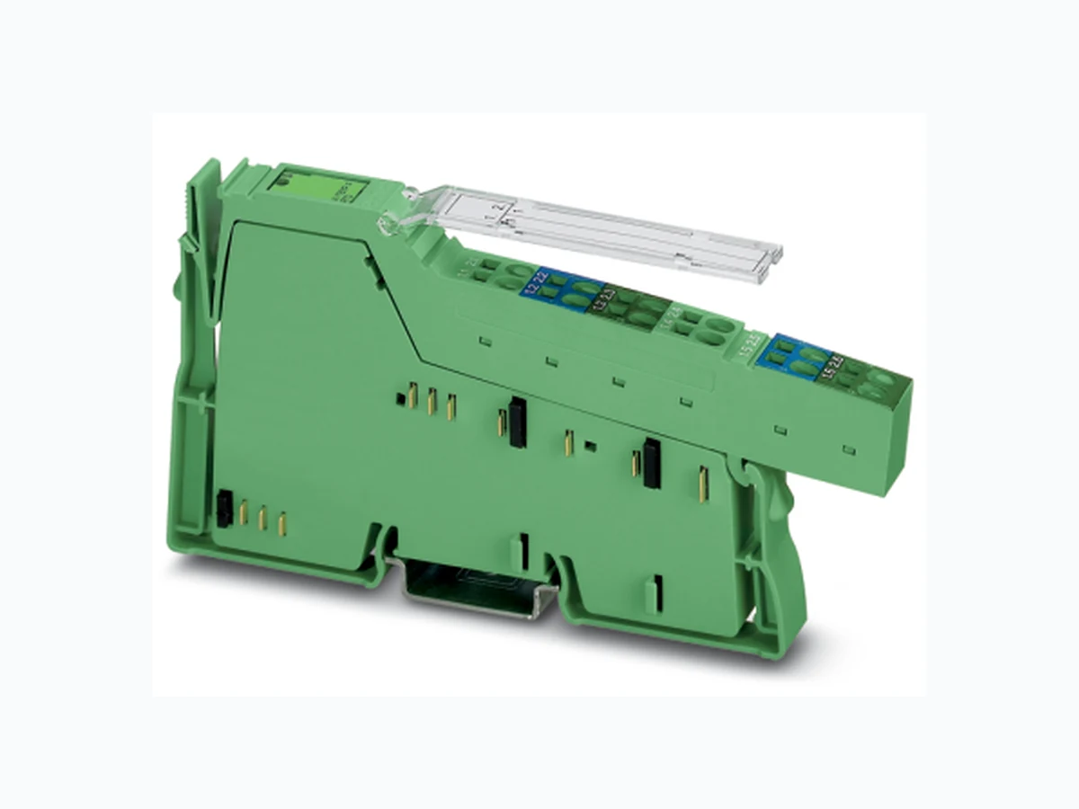
– Four measuring inputs that can be configured as – Voltage inputs 0 V ... 10 V – Inputs for resistance measurements up to 300 k Ω with output either in ohms or percent (potentiometer measurement) – Input for temperature measurements – The terminal supports – Platinum sensors according to DIN EN 60751/ IEC 60751 and the SAMA guideline – Nickel sensors according to DIN 43760 and the SAMA guideline – KTY81-110, KTY81-210, KTY84 sensors – Viessmann Ni 500, Viessmann NTC10 k sensors – Siemens LG-Ni 1000 sensor – Connection of sensors in 2-wire technology – Communication via process data – Channels are configured in dependently of one another using the bus system. – Diagnostic indicators – Can be used under extreme ambient conditions –P a i n t e d P C B s – Extended temperature range of -40°C … +70°C (see “Tested successfully: Use under extreme ambient conditions” on page 5) Inline analog input terminal, version for extreme conditions, 4 inputs, 2-wire connection method This data sheet is only valid in association with the IL SYS INST UM E user manual. Make sure you always use the latest documentation. It can be downloaded at phoenixcontact.net/products.
IB IL AI/TEMP 4 RTD-XC-PAC 8360_en_00 PHOENIX CONTACT 2/1 9 Table of contents
IB IL AI/TEMP 4 RTD-XC-PAC 8360_en_00 PHOENIX CONTACT 3/1 9 2O r d e r i n g d a t a
3 Technical data
Description Type Order No. Pcs. / Pkt. Inline analog input terminal, version for extreme conditions, complete with accessories (connector and labeling field), 4 inputs, 0-10 V, resistance temperature detector (RTD), 2-wire connection technology IB IL AI/TEMP 4 RTD-XC-PAC 2701165 1 Accessories Description Type Order No. Pcs. / Pkt. Connector as replacement item IB IL SCN-12-OCP 2727624 10 Documentation Description Type Order No. Pcs. / Pkt. “Automation terminals of the Inline product range” user manual IL SYS INST UM E 2698724 1 Dimensions (nominal sizes in mm) Housing dimensions (width x height x depth) 12.2 x 140.5 x 71.5 mm 140,5 119,8 71,5 General data Color Green Weight 68 g (with connector) Operating mode Process data mode with 2 words Connection method for sensors 2-wire technology Ambient temperature (operation) -25°C ... +55°C (Standard) -40 °C ... +70°C (Extended, see also the “Tested successfully: Use under extreme ambient conditions” section of the data sheet). Ambient temperature (storage/transport) -40 °C ... +85°C Permissible humidity (operation/storage/transport) 10% ... 95%, according to DIN EN 61131-2 Permissible air pressure (operation/storage/transport) 70 kPa ... 106 kPa (up to 3000 m above sea level) Degree of protection IP20 Protection class III, IEC 61140, EN 61140, VDE 0140-1
IB IL AI/TEMP 4 RTD-XC-PAC 8360_en_00 PHOENIX CONTACT 4/1 9 Connection data Designation Inline connector Connection method Spring-cage connection Conductor cross section [AWG] 28 ... 16 Inline local bus interface Connection method Inline data jumper Transmission speed 500 kbps Power consumption Communications power UL 7.5 V Current consumption from UL ≤ 60 mA (typical) Total power consumption ≤ 0.45 W (typical) Supply of the module electronics and I/O through bus coupler/power terminal Connection method Potential routing Analog inputs Number 4 Connection of signals 2-wire, shielded sensor cable Sensor types that can be used Pt, Ni, KTY, voltage 0 V ... 10 V Standards for characteristic curves According to DIN EN 60751: 07/1996/ according to SAMA RC 21-4-1966 Conversion time of the A/D converter 150 ms Process data update time of all four channels 600 ms Protective equipment None Electrical isolation The terminal is only supplied with power from the logic circuit (communications power UL = 7.5 V). All four analog inputs refer to one potential that is electrically isolated from all other circuits (UL, main circuit UM, segment circuit US, analog circuit UANA). FE (functional earth ground) is a separate potential area that is connected with shield and analog ground via a coupling network consisting of a 1 MΩ resistor and a 1 nF capacitor connected in parallel. Separate potentials in the IB IL AI/TEMP 4 RTD-XC-PAC terminal Test distance Test voltage Analog inputs / UL, UM, US, UANA 500 V AC, 50 Hz, 1 min Error messages to the higher-level control or computer system None Error messages via process data Peripheral fault/user error Yes (see page 16) Mechanical requirements Vibration, IEC 60068-2-6; EN 60068-2-6 5g Shock, IEC 60068-2-27; EN 60068-2-27 30g
IB IL AI/TEMP 4 RTD-XC-PAC 8360_en_00 PHOENIX CONTACT 5/1 9
4 Tested successfully: Use unde r extreme ambient conditions
XC terminals have been tested successfully over 250 temperature change cycles in accordance with IEC 61131-2 in the range from -40°C to +70°C. The following conditions were observed: – The Inline devices for all connecting cables were connected with a minimum conductor cross section of 0.5 mm² – The Inline station was inst alled on a wall-mounted horizontal DIN rail – Fans were used to ensure continuous movement of air in the control cabinet – The Inline station was not exposed to vibration or shock – The Inline station was oper ated with a maximum of
24.5 V (ensured by using regulated power supply units)
Figure 1 Temperature change cycle Programming data Local bus (INTERBUS) ID code 5Fhex (95dec) Length code 02 hex Input address area 2 words Output address area 2 words Parameter channel (PCP) 0 bytes Register length (bus) 2 words For the programming data/configuration data of other bus systems, please refer to the corresponding electronic device data sheet (e.g., GSD, EDS). Approvals For the latest approvals, please visit www.phoenixcontact.net/catalog. Temperature in the control cabinet/ambient temperature Cycle WARNING: The terminal is not approved for use in potentially explosive areas. The terminal is not approved for use in safety technology. 3 h + 30 min 3 h + 30 min (3 0,6) K/min+
3 K+Tmin
2 K+Tmax
IB IL AI/TEMP 4 RTD-XC-PAC 8360_en_00 PHOENIX CONTACT 6/1 9
5 Internal circuit diagram
Figure 2 Internal circuit diagram UL+ UANA UL- Local bus +24V US +24V UM µC MUX 3.3V UL REF EEPROM OPC OPC Protocol chip Microcontroller with multiplexer and analog digital converter- DC/DC converter with electrical isolation Coupling network Analog ground Optocoupler Voltage reference Non volatile memory- EEPROM REF µC MUX 3.3V UL Other symbols used are explained in the IL SYS INST UM E user manual.
IB IL AI/TEMP 4 RTD-XC-PAC 8360_en_00 PHOENIX CONTACT 7/1 9
6 Local diagnostic indicator
Figure 3 Local diagnostic indicator Function identification Green
7 Terminal point assignment
Figure 4 Terminal point assignment 2-wire connection Des. Color Meaning D Green Diagnostics D Terminal points Signal Assignment 1.1 +AI 1 Resistance/voltage input of channel 1
1.2 AGND* Sensor ground of channel 1
1.3 Shield* Shield connection of channel 1
1.4 +AI 2 Resistance/voltage input of channel 3
1.5 AGND* Sensor ground of channel 3
1.6 Shield* Shield connection of channel 3
2.1 +AI 3 Resistance/voltage input of channel 2
2.2 AGND* Sensor ground of channel 2
2.3 Shield* Shield connection of channel 2
2.4 +AI 4 Resistance/voltage input of channel 4
2.5 AGND* Sensor ground of channel 4
2.6 Shield* Shield connection of channel 4
- AGND and shield are connected internally. 1.1 2.1 1.2 2.2 1.3 2.3 1.4 2.4 1.5 2.5 1.6 2.6 1.1 1.2 1.3 1.4 1.5 1.6 2.1 2.3 2.4 2.2 2.5 2.6
IB IL AI/TEMP 4 RTD-XC-PAC 8360_en_00 PHOENIX CONTACT 8/1 9
8 Installation instructions
High current flowing through potential jumpers UM and US leads to a temperature rise in the potential jumpers and inside the terminal. To keep the current flowing through the potential jumpers of the analog terminals as low as possible, always place the analog terminals after all the other terminals at the end of the main circuit (for the sequence of the Inline terminals, see also IL SYS INST UM E user manual).
9 Connection notes
10 Connection examples
Figure 5 Examples for connecting RTDs and sensors for voltage measurement Always connect the analog sensors using shielded, twisted pair cables. A shield may reduce the influence of electromagnetic interference. Connect the shield at one end with the shield connection of the terminal and insulate it at the sensor. Connect unused sensor inputs with sensor ground. Connect the shield externally in areas with strong EMI, and insulate it at the device and the sensor AI/TEMP 4 RTD 1.5 2.5 1.6 2.6 D 1.2 2.2 1.3 2.3 1.4 2.4 1.1 2.1 +AI1 AGND Shield +AI2 AGND Shield +AI3 AGND Shield +AI4 AGND Shield AI/TEMP 4 RTD 1.5 2.5 1.6 2.6 D 1.2 2.2 1.3 2.3 1.4 2.4 1.1 2.1 +AI1 AGND Shield +AI2 AGND Shield +AI3 AGND Shield +AI4 AGND Shield OUT1 OUT3 OUT2 OUT4
IB IL AI/TEMP 4 RTD-XC-PAC 8360_en_00 PHOENIX CONTACT 9/1 9
11 Process data
11.1 Process data output words OUT
Two process data output words are available. Configure the terminal channels via the process data output words OUT1 and OUT2. In this context, the output word OUT1 contains the command and output word OUT2 contains the parameters belonging to this command. The configuration settings are stored in a volatile memory. If you change the configuration, the message "Measured value invalid" appears (diagnostic code 8004hex), until new measured values are available.
11.1.1 Output word OUT1 (control word)
Bit 15 to bit 8 (command code): CC = Channel number Bit 9 and bit 8: Channel number Please note that extended diagnostics is only possible if the IB IL format or standardized representation are configured as the format for representing the measured values. As the IB IL format is preset on the terminal, it is available immediately after the voltage has been applied. OUT1 B i t 1 5 1 4 1 3 1 2 1 1 1 0 9876543210 Assignment C o m m a n d c o d e 00000000 Bit 15 to bit 8 OUT1 Command function 0 0 0 0 0 0 C C 0x00hex Read measured value in IN2 channel-by-channel. 0 0 0 1 0 0 C C 1x00hex Read configuration in IN2 channel-by-channel. 0 0 1 1 1 1 0 03 C 0 0 hex Read firmware version and module ID in IN2. 0 1 0 0 0 0 C C 4x00hex Configure channel, configuration in OUT2. 0 1 0 1 0 0 C C 5x00hex Configure channel and read measured value of the channel, configuration in OUT2, measured value in IN2. 1 0 0 1 0 0 C C 9x00hex Read and write R0 value of the channel. Code Channel number dec bin 0 00 Channel 1 1 01 Channel 2 2 10 Channel 3 3 11 Channel 4
IB IL AI/TEMP 4 RTD-XC-PAC 8360_en_00 PHOENIX CONTACT 10 / 19
11.1.2 Output word OUT2 (parameter word)
The parameters for the commands 4x00hex, 5x00hex, and 9x00hex must be specified in OUT2. This parameter word is only evaluated for these commands. Commands 4x00hex, 5x00hex: Command 9x00hex: The following configurations are possible: Selecting the resistance of the sensor at 0°C; The configurable nominal resistance R0 is taken for the temperature calculation based on nickel and platinum sensors. Should the desired resistance not be found in the code table, the nominal resistance of 1Ω to 65535 Ω can be configured with increments of 1 Ω. To do this, use the command 9x00hex with the R0 value in the OUT2 process data word. Filter Selection of mean value generation. After every conversion, the measured value is saved in a mean value memory via which the mean value is generated. The memory size can be selected with the filter option. E.g., for a 16-sample mean value, the mean value is generated using the last 16 measured values. Resolution Quantization of the measured value, select between °Celsius or °Fahrenheit. Format Representation of the measured value in the IN process data Sensor type Sensor type setting; The configurable sensor type determines the conversion of the electrical signal present at the input into a physical size. Sensor type and measurement mode must be set for a sensor to be connected to receive a measuring result with a suitable accuracy. If, for instance, a Pt 1000 sensor is to be connected, a resistance measurement for the range from 0 Ω ... 3 kΩ can be used as a measurement mode. Also, a resistance measurement would be possible for the range from 0 Ω ... 300 kΩ, however, this measurement mode provides a considerably lower accuracy in the resistance range relevant for Pt 1000. Measurement mode Setting the selected measurement mode; The measuring mode determines the signal conditioning by the configurable inputs. Every input can be configured for voltage or resistance measurement as desired. For the resistance measurement, an auxiliary current that generates a voltage drop over the resistance to be measured is generated. The current supply is deactivated for the voltage measurement. The parameter word is only evaluated when the control word contains a valid command code. Reserved parameters may not be used. OUT2 B i t 1 5 1 4 1 3 1 2 1 1 1 0 9876543210 Assignment R0 Filter Resolution Format Sensor type Measurement mode OUT2 B i t 1 5 1 4 1 3 1 2 1 1 1 0 9876543210 Assignment R0 value, 1 Ω increments Configuration Short desig- nation Default Value of reference resistance R0 R0 1000 Ω Selection of mean value generation (filtering) Filter No mean value Resolution settings Resolution 0.1 Ω/0.01%/0.01 K Selection of formats for the representation of measured values Format IB IL format Sensor type setting Sensor type 0 V ... 10 V Setting the measurement mode Measure- ment mode Voltage measurement 0 V ... 10 V The resolution for voltage measurements depends only on the transmission format.
IB IL AI/TEMP 4 RTD-XC-PAC 8360_en_00 PHOENIX CONTACT 11 / 19
11.1.3 Parameters for configuration
The values in bold are default settings. Bit 15 to bit 13 Bit 12 and bit 11 Bit 10 and bit 9 Bit 8 and bit 7 Bit 6 to bit 3: Bit 2 to bit 0: Code Nominal resistance R0 [Ω] dec bin hex 0 000 0 1000 1 001 1 100 2 010 2 500 3 011 3 2000 4 100 4 5000 5 101 5 10000 6 110 6 Reserved 7 111 7 20000 (can be set) Code Filter dec bin 00 0 N o m e a n v a l u e 10 1 8 - s a m p l e m e a n v a l u e 2 10 32-sample mean value 3 11 Reserved Code Resolution for sensor type dec bin 1 (Resistance [Ω]) (Potentio- meter [%]) 3 ... 12 (Tempe- rature) 0 00 0.1 0.01 0.01°C 10 1 1 0 . 1 0 . 1 ° C 2 10 10 1 0.01°F 3 11 Reserved 0.1°F Code Format dec bin 0 00 IB IL (15 bits + sign bit with extended diagnostics) 10 1 I B S T (12 bits + sign bit + 3 diagnostic bits) 2 10 S7-compatible (15 bits + sign bit) 3 11 Standardized representation (15 bits + sign bit with extended diagnostics) Code Sensor type dec bin 0 0000 0 V ... 10 V 1 0001 Resistor 2 0010 Potentiometer [%] 3 0011 Pt DIN 4 0100 Pt SAMA 5 0101 Ni DIN 6 0110 Ni SAMA 7 0111 KTY 81-110 8 1000 KTY 81-210 9 1001 KTY 84 10 1010 Ni 1000 (Siemens LG) 11 1011 Ni 500 (Viessmann) 12 1100 NTC 10 k (Viessmann) 13 1101 Reserved 14 1110 Reserved 15 1111 Not configured Code Measurement mode dec bin 0 000 Voltage measurement 0 V ... 10 V 10 0 1 R e s e r v e d 20 1 0 R e s e r v e d 3 011 Resistance measurement 0 Ω ... 3 kΩ 4 100 Resistance measurement 0 Ω ... 300 kΩ 51 0 1 R e s e r v e d 61 1 0 R e s e r v e d 7 111 Not configured
IB IL AI/TEMP 4 RTD-XC-PAC 8360_en_00 PHOENIX CONTACT 12 / 19
11.2 Process data input words IN
11.2.1 Input word IN1 (status word)
The IN1 word is a copy of the OUT1 process data word. Mirroring of the command code: A command code mirrored from the control word.
11.2.2 Input word IN2
The measured values, the configuration or the firmware version are transmitted to the controller board or the PC via the process data input word IN2 according to the configuration. For control word 3C00 hex, IN2 provides the firmware version and the module ID. Example: Firmware version 1.23: For control word 9x00hex, IN2 provides the configuration and R0. Basically four formats are available for the representation of the measured values. For more detailed information on the formats, please refer to “Formats for representing measured values” on page 13. IB IL, S7-compatible, standardized representation formats IB ST format IN1 B i t 1 5 1 4 1 3 1 2 1 1 1 0 9876543210 Assignment M i r r o r i n g o f t h e c o m m a n d c o d e 00000000 IN2 B i t 1 51 41 31 21 11 09 8 7 6 5 4 3 2 1 0 Assign- ment (hex) 12 3 E hex Meaning Firmware version 1.23 Module ID MSB LSB 15 14 13 12 11 10 9 8 7 6 5 4 3 2 1 0 Configuration / R0 MSB LSB 15 14 13 12 11 10 9 8 7 6 5 4 3 2 1 0 SB Analog value MSB LSB 15 14 13 12 11 10 9 8 7 6 5 4 3 2 1 0 SB Analog value 0 O C O R MSB Most significant bit LSB Least significant bit SB Sign bit
0 Reserved
IB IL AI/TEMP 4 RTD-XC-PAC 8360_en_00 PHOENIX CONTACT 13 / 19
12 Formats for represen ting measured values
12.1 IB IL format (default setting)
The measured value is represented in bits 14 to 0. An additional bit (bit 15) is available as a sign bit. This format supports extended diagnostics. Values >8000hex and <8100hex indicate an error (see “Diagnostic codes in the in formats IB IL and standardized representation” on page 16). Measured value representation in IB IL format, 15 bits Typical analog values MSB LSB 15 14 13 12 11 10 9 8 7 6 5 4 3 2 1 0 SB Analog value SB Sign bit Sensor type Voltage Resistance Potentiometer Temperature Sensor/code 0 1 2 3 ... 12 Resolution (bits 10 and 9) – 00bin 01bin 01bin/11bin Process data item (= analog value) [V] [Ω] [%] [°C]/[°F] hex dec 8001 -32767 > 10.837 > 3251.2 1 1 In the resistance measurement mode 0 Ω 3 kΩ is limited to 3000.0 Ω. > 3251.2 > 3251.2 7F00 32512 10.837 3251.2 1 3251.2 3251.2 7530 30000 10.000 3000.0 3000.0 3000.0 0001 1 0.333 mV 0.1 0.1 0.1 0000 0 0 0 0 0
IB IL AI/TEMP 4 RTD-XC-PAC 8360_en_00 PHOENIX CONTACT 14 / 19
12.2 IB ST format
The measured value is represented in bits 14 to 3. The remaining 4 bits are sign and error bits. Measured value representation in IB ST format, 12 bits Typical analog values MSB LSB 15 14 13 12 11 10 9 8 7 6 5 4 3 2 1 0 SB Analog value 0 OC OR SB Sign bit OC Open circuit/short circuit OR Overrange Sensor type Voltage Resistance Potentiometer Temperature Sensor/code 0 1 2 3 ... 12 Resolution (bits 10 and 9) – 00bin 01bin 01bin/11bin Process data item (= analog value) [V] [Ω] [%] [°C]/[°F] hex dec 7FF9 32761 Value is outside the valid range 7FF8 32760 9.999 3276.0 1 1 In the resistance measurement mode 0 Ω 3 kΩ is limited to 3000.0 Ω. 3276.0 3276.0 4000 16384 5.000 1638.4 1638.4 1638.4 2710 10000 3.052 1000.0 1000.0 1000.0 0008 8 2.441 mV 0.8 0.8 0.8 0002 2 - Open circuit 0001 1 Value is outside the valid range 0000 0 0.000 0.0 0.0 0.0 FC18 -1000 -0.305 - - -100.0 8001 -32767 Value is outside the valid range If the measured value is outside the representation area of the process data, bit 0 is set to 1. In the event of an open/short circuit, bit 1 is set to
IB IL AI/TEMP 4 RTD-XC-PAC 8360_en_00 PHOENIX CONTACT 15 / 19
12.3 S7-compatible format
The measured value is represented in bits 14 to 0. An additional bit (bit 15) is available as a sign bit. Overrange or underrange are indicated with the values 7FFFhex or 8000hex. Measured value representation in S7-compatible format; 15 bits Typical analog values MSB LSB 1 5 1 4 1 3 1 2 1 1 1 0 9876543210 SB Analog value SB Sign bit Sensor type Voltage Resistance Potentiometer Temperature Sensor/code 0 1 2 3 ... 12 Resolution (bits 10 and 9) – 00bin 01bin 01bin/11bin Process data item (= analog value) [V] [Ω] [%] [°C]/[°F] Hex Dec 7FFF 32767 Overrange 6C00 27648 10.000 2764.8 2764.8 2764.8 2710 10000 3.617 1000.0 1000.0 1000.0 03E8 1000 0.362 100.0 100.0 100.0 0001 1 3.617 mV 0.1 0.1 0.1 0000 0 0.000 0.0 0.0 0.0 FC18 -1000 -0.362 - - -100.0 8000 32768 Underrange
IB IL AI/TEMP 4 RTD-XC-PAC 8360_en_00 PHOENIX CONTACT 16 / 19
12.4 Standardized representation format
The measured value is represented in bits 14 to 0. An additional bit (bit 15) is available as a sign bit. The data is standardized with regard to measuring range and resolution and does not need to be converted. The setting of the resolution is 1Ω for resistance measurements and 1°C for temperature measurements. It has no influence on voltage measurements. This format supports extended diagnostics. Values >8000hex and <8100hex indicate an error (see “Diagnostic codes in the in formats IB IL and standardized representation” on page 16). Measured value representation in S7-compatible format, 15 bits Typical analog values Resolution 0.1
13 Diagnostic codes in the in formats
The following diagnostic codes are possible: MSB LSB 1 5 1 4 1 3 1 2 1 1 1 0 9876543210 SB Analog value SB Sign bit Sensor type Voltage Resistance Potentiometer Temperature Sensor/code 0 1 2 3 ... 12 Resolution (bits 10 and 9) – 00bin 01bin 01bin/11bin Process data item (= analog value) [V] [Ω] [%] [°C]/[°F] hex dec 8001 32769 >10.837 - - - 2710 10000 10.000 1000.0 1000.0 1000.0 0001 1 0.001 0.1 0.1 0.1 0000 0 0.000 0.0 0.0 0.0 FFFF -1 - - - -0.1 FC18 -1000 -1.000 - - -100.0 Code (hex) Error
8001 Overrange
8002 Open circuit (only for resistance measurements)
8004 Measured value invalid/no valid measured value
available (e.g., because channel was not configured)
8010 Configuration invalid (after a reset or with an
invalid configuration)
8040 Terminal faulty
8080 Underrange
IB IL AI/TEMP 4 RTD-XC-PAC 8360_en_00 PHOENIX CONTACT 17 / 19
14 Selecting measuring ranges and sensors
14.1 Systematic errors
Systematic errors can cause large measuring error when measuring resistances and also with temperature measurements with RTDs. The largest systematic error for resistance measurements with 2-wire connection method is the influence of the sensor connecting cables and contact resistances. Measuring errors may be more or less large depending on the resistance ratio between sensor supply cable and the coefficient of the sensor. This error can only be compensated to a limited extent by subsequent calibration since the resistance of the connecting cable depends on the temperature. The temperature coefficient of Pt 100 sensors is approximately 0.385 Ω/K. The resistance of a 10 m connecting cable with a cross-section of 0.5 mm² is approximately 0.712 Ω and, therefore, falsifies the measuring result by almost 2 K. In addition there is the temperature-dependent change of the cable and contact resistances. For Pt 1000, the temperature coefficient is 10 times higher than for Pt 100 and the effect of cable and contact resistances is 10 times lower. Other temperature coefficients, such as NTC sensors, offer considerably higher temperature coefficients.
14.2 Tolerance and drift
The influence of measuring errors resulting from tolerance and drift of the measuring circuit can be minimized by selecting appropriate measuring ranges and sensor types. Basically the same recommendations apply as for the systematic errors. The table “Tolerances of the measurement modes” on page 18 provides an overview of the tolerances and drift of the measuring ranges of the device. The table “Selected sensor parameters” on page 19 gives an overview of temperature coefficients of selected sensor types so that in connection with table “Tolerances of the measurement modes” on page 18 it can be estimated which errors might result for certain sensor measuring combinations. Select sensor types with the greatest possible temperature coefficients to minimize the influence of systematic measuring errors. We recommend sensors of the appropriate type (preferably NTC) or sensors with a nominal resistance of more than 1000 Ω (with Ni or Pt). Please note the information given under “Installation instructions” on page 8 to minimize a temperature rise of the terminal within the Inline station and a temperature drift of the terminal.
IB IL AI/TEMP 4 RTD-XC-PAC 8360_en_00 PHOENIX CONTACT 18 / 19 Tolerances of the measurement modes Measurement mode Range1 Tolerance Typical Maximum Absolute Relative2 Absolute Relative2 TA = 25°C 5 kΩ - 20 kΩ ±20 Ω ±0.1% ±40 Ω ±0.2% 20 kΩ - 100 kΩ ±300 Ω ±0.3% ±600 Ω ±0.6% 100 kΩ - 300 kΩ ±2500 Ω ±0.8% ±5000 Ω ±1.7% TA in the range from -25°C to +55°C 0 Ω ... 3 kΩ 0 kΩ - 2.2 kΩ 5 kΩ - 20 kΩ ±80 Ω ±0.4% ±160 Ω ±0.8% 20 kΩ - 100 kΩ ±1500 Ω ±1.5% ±3000 Ω ±3.0% 100 kΩ - 300 kΩ ±12000 Ω ±4.0% ±24000 Ω ±8.0% 1 A measuring mode may cover several virtual ranges. Each is considered separately since the accuracy highly varies across the entire range. 2 Relative data refers to the upper lim it of the respective measuring range. 3 Tolerances only valid up to 2.2 k Ω. The percentage tolerance values refer to the respective positive measuring range final value. Unless stated otherwise, nominal operation (nominal voltage, preferred mounting position, default format, default filter setting, identical measuring range setting for channels) is used as the basis. The tolerance values refer to the operating temperature range specified in the tables. The operable range outside this range is not taken into consideration. Please also observe the values for temperature drift and the tolerances under influences of electromagnetic interference. The maximum tolerance values represent the worst case measurement inaccuracy. They contain the theoretical maximum possible tolerances in the corresponding measuring ranges as well a the theoretical maximum possible tolerances of the calibration and test equipment.
IB IL AI/TEMP 4 RTD-XC-PAC 8360_en_00 19 / 19PHOENIX CONTACT GmbH & Co. KG • Flachsmarktstraße 8 • 32825 Blomberg • Germany phoenixcontact.com Selected sensor parameters Sensor type Temperature range Resistance range Temperature coefficient at 25°CFrom To From To NTC10 k, B = 3988 0°C 70°C 32650.0 Ω 1752.0 Ω -461.00 NTC20 k, B = 4300 0°C 70°C 71126.0 Ω 3061.0 Ω -996.00 Pt 1000 DIN -100°C 850°C 603.4 Ω 3904.8 Ω 3.88 Pt 1000 SAMA -200°C 600°C 166.6 Ω 3118.7 Ω 3.88 Ni 1000 DIN -60°C 180°C 695.2 Ω 2232.2 Ω 5.81 Ni 1000 SAMA Type I -40°C 200°C 779.0 Ω 2490.2 Ω 6.11 KTY81-110 -55°C 150°C 490.0 Ω 2211.0 Ω 7.80 KTY81-210 -55°C 150°C 980.0 Ω 4280.0 Ω 15.60 KTY84 -40°C 300°C 359.0 Ω 2624.0 Ω 4.40 Siemens LG Ni 1000 -30°C 160°C 871.7 Ω 1863.6 Ω 4.70 Viessmann Ni 500 -40°C 40°C 412.0 Ω 576.0 Ω 2.40 Viessmann NTC 10 k 10°C 110°C 20000.0 Ω 400.0 Ω -625.00