
DATASHEET SEARCH SITE
Document overview
- Manufacturer or author: Provided By www.digicamel.com(FREE DATASHEET DOWNLOAD SITE)
- PDF pages: 13
Technical content
Features
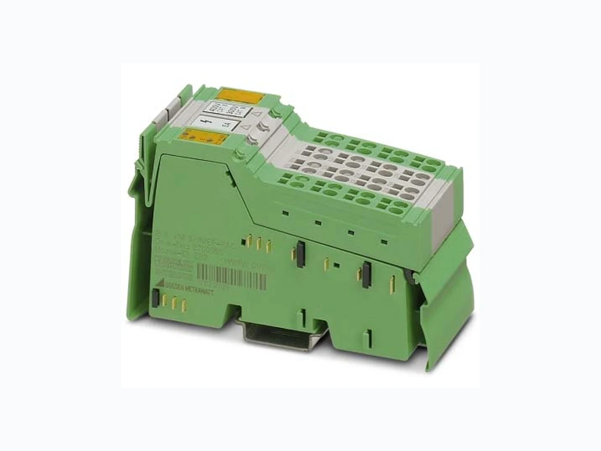
– Four 1 A/5 A AC inputs for phase currents and neutral conductor current – Supports direct connection of three inputs for phase conductor voltages up to 690 V AC – Triggers for measurement intervals can be freely de- fined – Harmonics analysis – Determination of maximum values – Operating hours counter –P o w e r m e t e r – Bimetal filtering – Short-time control – Diagnostic and status indicators This data sheet is only valid in association with the IL SYS INST UM E Inline user manual. For more detailed information on the power measurement terminal, please refer to the UM EN IB IL PM 3P/N/ EF-PAC user manual. Make sure you always use the latest documentation. It can be downloaded at phoenixcontact.net/products. Inline modular power measurement terminal
IB IL PM 3P/N/EF(-2MBD)-PAC 8214_en_08 PHOENIX CONTACT 2 Table of contents
IB IL PM 3P/N/EF(-2MBD)-PAC 8214_en_08 PHOENIX CONTACT 3 2O r d e r i n g d a t a
3 Technical data
Description Type Order No. Pcs. / Pkt. Inline modular power measurement terminal for direct measurement of AC currents up to 5 A, including neutral conductor current and phase conductor voltages up to 400 V AC (phase to neutral conductor) or 690 V AC (phase to phase) complete with accessories (connectors and labeling fields) IB IL PM 3P/N/EF-PAC 2700965 1 Inline modular power measurement terminal for direct measurement of AC currents up to 5 A, including neutral conductor current and phase conductor voltages up to 400 V AC (phase to neutral conductor) or 690 V AC (phase to phase) complete with accessories (connectors and labeling fields). Transmission speed: 2 Mbaud IB IL PM 3P/N/EF-2MBD-PAC 2700576 1 Accessories Description Type Order No. Pcs. / Pkt. Current transformer PACT MCR ... See Phoenix Contact catalog Documentation Description Type Order No. Pcs. / Pkt. “Automation terminals of the Inline product range” user manual IL SYS INST UM E – – “Inline Modular power measurement terminal: connection methods, operating modes, process data and PCP” user manual UM EN IB IL PM 3P/N/EF(-2MBD)-PAC – – Dimensions (nominal sizes in mm) Width 48.8 mm Height 136 mm Depth 71.5 mm 140,5 119,8 71,5 General data Color Green Weight 200 g Number of connectors 4 (coded) Operating mode Process data mode with 12 words/PCP with 2 words Permissible temperature (operation) -25°C ... +60°C Permissible temperature (storage/transport) -25°C ... +85°C Permissible humidity (operation/storage/transport) 10% ... 95% without condensation (according to IEC 61131-2) Permissible air pressure (operation/storage/transport) 80 kPa ... 106 kPa (up to 2000 m above sea level)
IB IL PM 3P/N/EF(-2MBD)-PAC 8214_en_08 PHOENIX CONTACT 4 Measuring category CAT II/400 V according to EN 61010-1 CAT III/300 V according to EN 61010-1 Real energy accuracy According to IEC 62053-21 Class 1 Reactive energy accuracy According to IEC 62053-23 Class 2 Degree of protection IP20 according to IEC 60529 Protection class III, IEC 61140, EN 61140, VDE 0140-1 General data Connection data Designation Inline connector plug Connection method Spring-cage connection Conductor cross section 0.2 mm² to 1.5 mm² (solid or stranded), AWG 24 - 16 Inline local bus interface Connection method Inline data jumpers Transmission speed of IB IL PM 3P/N/EF-PAC 500 kbps Transmission speed of IB IL PM 3P/N/EF-2MBD-PAC 2 Mbps Power consumption Communications power UL 7.5 V DC Current consumption from UL 130 mA, typical Power consumption at UL 1 W, typical Power dissipation 1 W, typical Inputs: Current measuring input 4 inputs for phase currents and neutral conductor current for direct current measurement up to 5 A AC: Adjustable nominal range 1 0 A … 1 A Adjustable nominal range 2 0 A … 5 A Currents greater than 5 A AC with AC current transformers (PACT): Adjustable transformer ratio 1 A ... 30,000 A 1 A or 5 A Adjustable transformer ratio range ±100 per mill Nominal value 1 A AC or 5 A AC Accuracy 0.25% of nominal value; for mains frequencies of 20 Hz ... 100 Hz Overload 140% continuous; 150 A for 10 ms (1 half wave at fN) Cable length 10 m, maximum (please observe the data of the measuring transducer) Inputs: Voltage measuring input Supports direct connection of 3 inputs for phase conductor voltages up to 690 V AC (phase to phase) Mains frequency 20 Hz ... 100 Hz Phase to phase 0 V AC ... 690 V AC Not phase to phase: phase - neutral (N) 0 V AC ... 400 V AC Neutral conductor (N) – ground 45 V AC, maximum There is no maximum voltage limit when voltage transducers are used: Adjustable transformer ratio range +/- 100 per mill Phase nominal value 400 V AC phase voltage (690 V/ √3) Neutral conductor maximum value 45 V AC to ground, maximum Measuring range 0 V AC ... 440 V AC Accuracy 0.25% of nominal value; for mains frequencies of 20 Hz ... 100 Hz Overload 120% continuous Cable length 10 m, maximum (please observe the data of the measuring transducer)
IB IL PM 3P/N/EF(-2MBD)-PAC 8214_en_08 PHOENIX CONTACT 5 Scanning rate Internal scanning values for each full wave for all measuring inputs 64, synchron ous with the mains frequency in the range 20 Hz ... 100 Hz Process data update Scanning measured values mode 10 values every 2 ms Other operating modes Period length (20 ms at 50 Hz) or multiples can be set Limitations No limitation of simultaneity, no derating Programming data ID code (hex) DC ID code (dec) 220 Length code (hex) 0C Length code (dec) 12 Process data channel 192 bits Input address area 12 words Output address area 12 words Parameter channel (PCP) 2w o r d s Register length (bus) 14 words For the programming data/configuration data of other bus systems, please refer to the corresponding electronic device data description (e.g., GSD, EDS). Error messages to the higher-level control or computer system Two phase conductors mixed up Yes, peripheral fault message One phase conductor not connected or phase conductor open circuit Yes, peripheral fault message Measuring circuit fault Yes, peripheral fault message Value range for transformer/transducer factors exceeded Yes, peripheral fault message Value range for other settings exceeded Yes, peripheral fault message Electrical isolation/isolation of the voltage areas Common potentials The voltage inputs are connected to the neutral conductor via protective impedance. The neutral conductor connection is safe to touch when not connected. (Total current <3.5 mA according to EN 61010-1: 2010) Separate potentials (Each at least 2.5 kV AC 1 minimum, according to EN 61010-1) The current inputs are isolated from all other circuits. Impulse withstand capability of current and voltage inputs 4 kV (according to EN 61010-1) 24 V main voltage UM, 24 V segment voltage US, 24 V analog power supply UANA, GND, and FE are not interrupted, are not used, and are isolated from all other potentials. UL+, UL-, and the local bus are isolated from all other potentials.
IB IL PM 3P/N/EF(-2MBD)-PAC 8214_en_08 PHOENIX CONTACT 6
4 Internal basic circuit diagram
Figure 1 Internal basic circuit diagram Signal isolation using current transformers Signal isolation using protective impedances Pseudo-synchronous multi-channel A/D converter Measuring potential(Measuring) CPU Signal transmission with electrical isolation Power supply with electrical isolation Inline local bus Bus driver Protocol chip SUPI4 Communications potential U+L U-L UANA L1 L2 L3 N I1 I2 I3 IN
IB IL PM 3P/N/EF(-2MBD)-PAC 8214_en_08 PHOENIX CONTACT 7
5 Local diagnostic and status indica-
Figure 2 Local diagnostic and status indicators
6 Terminal point assignment
Figure 3 Terminal point assignment LED Color Meaning D Green Diagnostics (bus and communica- tions power) On Bus active Flashing (0.5 Hz) Communications power present, bus not active Flashing (4 Hz) Local bus error TR Green PCP communication On PCP communication active E Red Error On An error has occurred: –T w o p h a s e c o n d u c t o r s m i x e d up (voltage paths) – Phase conductor not connect- ed (voltage paths) – Overload of measuring inputs – Measuring circuit fault – Firmware runtime error 400V 300V CAT II CAT III5A D TR E PM 3P/N/EF Connector Terminal point Assign- ment Remark Connector 1 (green) Not used Connector 2 (gray) I1l, I2l, I3l, INl Current measure- ment Output I1k, I2k, I3k, INk Current measure- ment Input Connector 3 (gray) U1, U2, U3 Voltage measure- ment UN Neutral conductor connec- tion (45 V AC, maximum) Remains open on three-wire mains without neutral con- ductors. Connector 4 (green) Not used 1234 /c731l U1 UN /c731k /c732l /c732k /c733l /c733k /c73NI /c73Nk
IB IL PM 3P/N/EF(-2MBD)-PAC 8214_en_08 PHOENIX CONTACT 8
7 Operating modes
You can run the terminal in different operating modes: – Basic measured values – Scanning measured values – Heating current measured values – Single-phase or three- phase synchronization
7.1 Basic measured values
Basic measured values measurement mode acquires mains variables. The basic measured values can be output by full wave or av- eraged over 2, 4, 8, or a multiple of 4 full waves. The following are mains variables: –M a i n s f r e q u e n c y –P h a s e v o l t a g e s – Phase conductor voltages – Phase currents – Neutral conductor current – Real, reactive, and apparent powers – Real power factors of the phases – Power flow direction – Power meter accuracy – For real energy: accordin g to IEC 62053-21 Class 1 – For reactive energy: according to IEC 62053-23 Class 2
7.2 Scanning measured values
Scanning measured values are the instantaneous values (scanning values) of a measured signal. You can select the following signals: –C u r r e n t o f a p h a s e – Voltage of a phase – Neutral conductor current – Instantaneous real power of a phase This measurement mode is used to analyze the curve shape of the measurement signal.
7.3 Heating current measured values
Heating current measured values are used for non-equiva- lence monitoring of heating systems for temperature con- trollers, in order to detect faults at an early stage before they can lead to overtemperature or undertemperature. – Measurement is the same as for basic measured val- ues. – The measured values are output per full wave. – Only phase currents and phas e voltages are measured. – If voltage compensation is activated (secondary nomi- nal heating voltage ≥50 V), heating current fluctuations caused by mains voltage fluctuations are compensat- ed. This corresponds to a conductivity measurement. – For evaluation, a function block is required that corre- lates the binary heating actuating signals of the control- ler instances with the measured values (non- equivalence monitoring).
7.4 Synchronization
The synchronization modes provide measured values which can be used to control the voltage, speed, and phase angle of a generator, so that connection to the mains is pos- sible. One-phase synchronization mode – Measurement is the same as for basic measured val- ues. – Economy circuits are not possible. – The measured values are output per full wave. – One phase voltage each from the mains, generator, and perhaps load, the phase angle between both voltages, and the frequency differences and the frequencies are measured. – The currents are measured independently. – Harmonics analysis and measurement of phase con- ductor voltages are not possible. The function block for PC Worx can be download- ed at phoenixcontact.net/products
IB IL PM 3P/N/EF(-2MBD)-PAC 8214_en_08 PHOENIX CONTACT 9 Three-phase synchronization mode – Connection and configuration are the same as for basic measured values. – Economy circuits are not possible. – The bus cycle triggers measurement of object 0089 hex. – All the basic measured values are also available. – The basic measured values are output per full wave. – In addition, the phase relati ons of each voltage and the average phase relation of the mains related to the bus cycle are calculated in order to be able to calculate the phase difference across several terminals. – Harmonics analysis is not available. Bus cycle for three-phase synchronization mode – The process data for control word 0900 hex (object 0089hex, synchronization angle) must only be request- ed at an interval of one period (20 ms at 50 Hz) plus about 4 ms or more because otherwise, synchroniza- tion would not be possible. If this is not the case, an er- ror message is output and the phase angles are invalid. – In between, any control words can be used to read ba- sic measured values. – The bus cycle should not be faster than about 4 ms be- cause synchronization would then be unreliable.
8 Description of individual functions
Triggers for measurement intervals can be freely de- fined Measurement intervals can be triggered at will for creating load profiles, e.g., using the synchronization pulse of the power supply company. The power values (real, reactive, and apparent power) of the elapsed interval averaged in the interval can be buffered for each interval in a remanent buf- fer in the controller ready for evaluation. Harmonics analysis FFT (Fast Fourier Transformation) is used to measure the r.m.s. values of both the fundamental waves and the har- monics of voltages and currents twice per second up to at least the 31st harmonic. The individual harmonic distortion and total harmonic distor- tion are then calculated from this. Determination of maximum values Maximum values by amount are determined for most mea- sured values. Operating hours counter Operating hours are counted whenever currents greater than 0.5% of the nominal current are flowing. Power meter Operating times for real and reactive power are counted separately for consumption and supply or for inductive and capacitive. S0 pulses S0 pulses can be forwarded for energy recording outside the controller. They are available in three different rates. Bimetal filtering Filtered values are also available for the currents. The filter characteristic corresponds to bimetal measuring devices with time settings from one to twenty minutes. Short-time control Some operations in the terminal have to be triggered in real- time. These include: – Freezing or resetting the power meter in order to ac- quire the energy consumption in an installation by pro- duction unit, for example – Triggering power intervals in order to create a load pro- file – Resetting maximum values – Acknowledging completion or a state This can be done via process data (control word 0C00 hex) or, in the case of non-time-critical operations, via PCP (ob- ject index 008Chex). The theoretical cycle time on the local bus can be determined using the Project+ software. To do so, create the station in Project+. The cycle time for the station is displayed under “Results/ Technical data”. The Project+ software can be downloaded at phoenixcontact.net/products.
IB IL PM 3P/N/EF(-2MBD)-PAC 8214_en_08 PHOENIX CONTACT 10
9 Connection methods
Whatever connection method is used, the currents and volt- ages can be connected directly or via transformers/trans- ducers. The following example shows the wiring for a four- wire three-phase mains with measurement of the neutral conductor current. The potential of a connected neutral conductor must be close to ground and must not exceed 45 V AC to ground.
9.1 Direct connection
The power measurement terminal has the advantage that currents can be connected directly, i.e., live. Direct connec- tion is possible up to a nominal current of 5 A and a phase voltage of up to 400 V. In addition, the measuring range can be switched between 1A a n d 5A . Configuration: – Primary and secondary phase conductor voltage = 0 (default) – Primary phase current = 0 (default) – Secondary phase current = 1 A or 5 A for measuring range switchover Figure 4 Direct connection
9.2 Connection with current transformers
Current transformers are required when connecting nominal currents higher than 5 A. Ground the transformers for safety and to reduce secondary sources of interference. Configuration: – Primary and secondary phase conductor voltage = 0 (default) – Primary and secondary phase current dependent upon the current transformer used Figure 5 Connection with current transformers XXX X X X N
IB IL PM 3P/N/EF(-2MBD)-PAC 8214_en_08 PHOENIX CONTACT 11
9.3 Connection with current transformers and volt-
At voltages higher than 400 VLN/690 VLL (measuring cate- gory CAT II) or 290 VLN/500 VLL (measuring category CAT III), voltage transducers are required for the connection. Ground the secondary neutral conductor connection of the transducers. In high-voltage networks, single-position isolated voltage transducers grounded at the cold end (connection X instead of V) are used. Currents Use current transformers when connecting the currents, as the current measuring inputs are only isolated up to 290 V or 400 V dependent upon the measuring category. Configuration: – Primary and secondary phase conductor voltage de- pendent upon the voltage transducer used – Primary and secondary phas e current dependent upon the current transformer used Figure 6 Connection with current transformers
IB IL PM 3P/N/EF(-2MBD)-PAC 8214_en_08 PHOENIX CONTACT 12
9.4 Overview of the configurat ion of connection methods
The connection method parameter of the Config Table ob- ject is used to configure the connection method. Designation Neutral con- ductor pres- ent Use Connec- tion method code Bit assignment in the con- nection method parame- ter of the Config Table object 7 6 5 4 3 2 1 0 Three-phase current No Three-wire three-phas e mains with uneven load 00hex 00 0 0 0 External two-wattmeter circuit I1 + L1-N No Three-wire three-phase mains with even load, only phase 1 is measured (economy circuit) 04hex 00 0 0 4 I1 + L1-L3 No Three-wire three- phase mains with even load (economy circuit) 05hex 00 0 0 5 Three-phase current Yes Four-wire three-phase mains with uneven load 10hex 00 1 0 0 3-phase Yes Any three phases, no rotating field 11 hex 00 1 0 1 Open-Y Yes Four-wire three- phase mains with uneven load, with just two voltage transducers (econ- omy circuit) 12hex 00 1 0 2 I1 + L1-N Yes Four-wire three- phase mains with even load, only phase 1 is measured (economy circuit) 14hex 00 1 0 4 Alternating cur- rent Yes Single-phase alternating current 16 hex 00 1 0 6 Split phase Yes Two-phase mains 17 hex 00 1 0 7 With neutral conductor cur- rent Yes On all networks which have a neutral conduc- tor, the neutral conductor current can be measured additionally whatever the type of circuit. 3xhex 01 1 0 x Bit 7, 6 Not relevant Bit 5 = 0 Neutral conductor current not connected Bit 5 = 1 Neutral conductor current connected Bit 4 = 0 Neutral conductor not connected Bit 4 = 1 Neutral conductor connected Bit 3 Not relevant Bit 2 ... 0 Type of circuit
IB IL PM 3P/N/EF(-2MBD)-PAC 8214_en_08 13PHOENIX CONTACT GmbH & Co. KG • 32823 Blomberg • Germany www.phoenixcontact.com
10 Process data words
The width of the process data channel is twelve words (word 0 ... 11): one control or status word and eleven data words. The process data records are consistent along their entire length; they are mapped in full in IN0 to IN11. If a process data record is shorter than twelve words, it is re- turned left-aligned and with zeros added. For a description of the process data, please refer to the UM EN IB IL PM 3P/N/EF-PAC user manual.
11 PCP
The width of the parameter channel is two words. For a description of the manufacturer-specific objects, please refer to the UM EN IB IL PM 3P/N/EF-PAC user manual.