
DATASHEET SEARCH SITE
Document overview
- Manufacturer or author: Provided By www.digicamel.com(FREE DATASHEET DOWNLOAD SITE)
- PDF pages: 12
Technical content
Features & Benefits
10 Gb/sTelecom & Datacom
– 80C08C and 80C12 – Low- noise, High Optical Sensitivity and Broad Wavelength Conformance Testing for 10GbE LAN, WAN, and FEC, 10G Fibre Channel, and
10 Gb/s Telecom Standard
– 80C11 30 GHz Optical Bandwidth Conformance Testing and Characterization for 10 Gb/s Telecom and Datacom Standards and FEC Rates – 80C08C and 80C11 Integrated Clock Recovery Supports All Current 10 Gb/s Standards or User Defined Rate from 9.8 to 12.6 Gb/s – 80C12 Clock Recovery Available Via 80A05 Clock Recovery Module
40 Gb/s Telecom
– 80C10 Provides 65 GHz Optical Bandwidth for Signal Characterization of 40 Gb/s RZ or NRZ Data – 80C10 Provides Reference Receivers for Conformance Testing of 39.813 Gb/s (OC-768/STM-256) and 43.018 Gb/s (ITU-T G.709 FEC) Tributary Telecom & Datacom – 80C07B and 80C12 Provide Excellent Optical Sensitivity and Broad Wavelength Test Capability – 80C07B, 80C12, 80C01 Multi-rate Telecom Conformance Testing Solutions from 155 Mb/s (OC-3/STM-4) Through
9.953 Gb/s (OC-192/
STM-64) and Datacom Conformance Testing Solutions for Fibre Channel, Ethernet and InfiniBand Standards
Applications
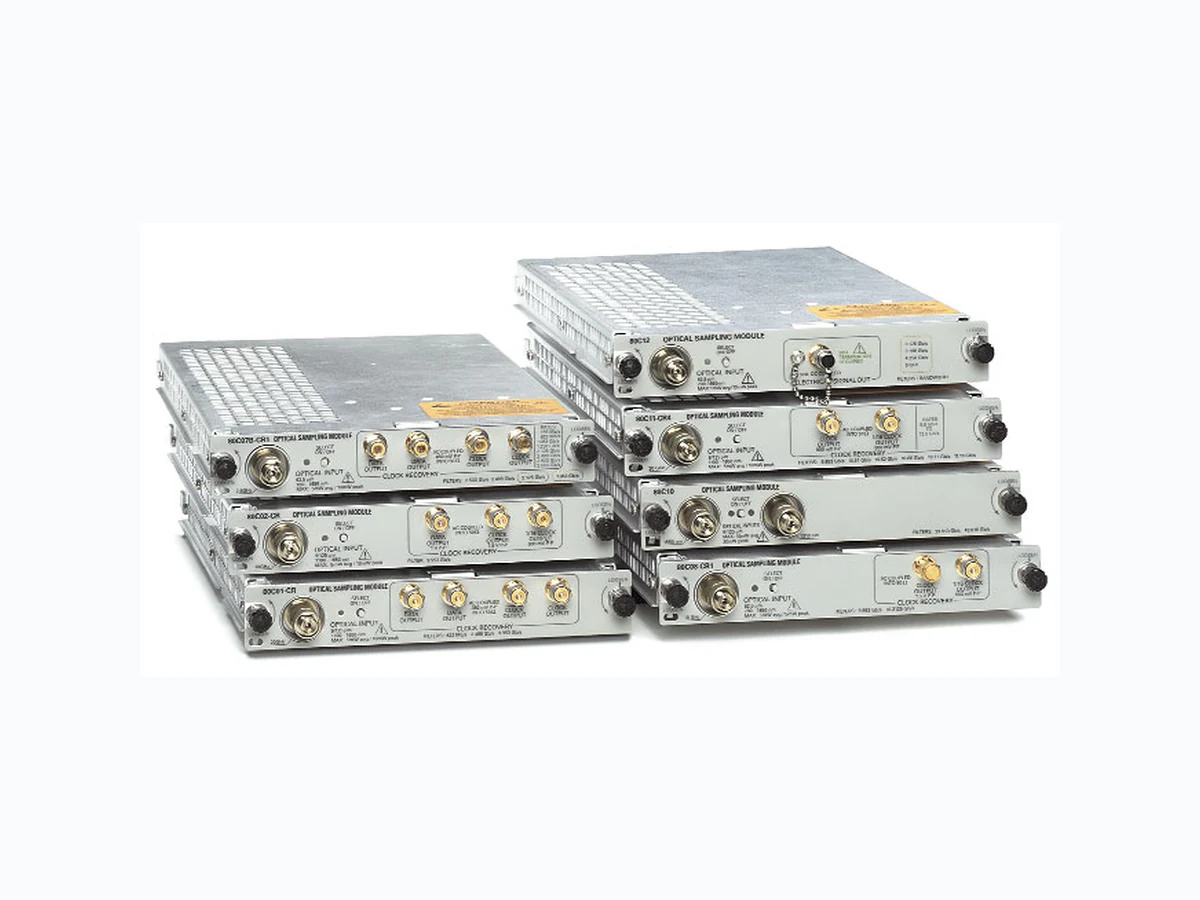
Extinction Ratio and Q-factor Measurements Eye-pattern and Pulse Shape Analysis Relaxation Oscillation Testing Optical Signal Analysis Conformance Testing NRZ and RZ Pulse Characterization Optical Sampling Modules 80C01 • 80C02 • 80C07B • 80C08C • 80C10 • 80C11 • 80C12 Optical Signal Analysis • www.tektronix.com/optical1 The CSA/TDS8000B Series Sampling Oscilloscopes, when configured with one or more optical sampling modules, provide complete optical test solutions for Telecom (155 Mb/s to 43.018 Gb/s) or Datacom (Fibre Channel, Gigabit Ethernet, 10GbE and InfiniBand) applications, as well as general purpose optical component testing. Each optical module includes all the elements necessary for optical testing: Optical to electrical converter Average power monitor One or more reference receiver filters A full bandwidth optical path A low-noise electrical sampler Optional integrated clock recovery (80C12 clock recovery is provided via the 80A05 Clock Recovery Module – sold separately) Universal optical input connector 80C01 Multi-rate Telecom Sampling Module – The 80C01 module supports waveform conformance testing of long- wavelength (1100 to 1650 nm) signals at 622, 2488 Mb/s and 9.953 Gb/s as well as general-purpose testing with up to 20 GHz optical bandwidth. With its clock recovery option, the 80C01 provides testing solutions for 622 and 2488 Mb/s telecom applications. 80C02 High-performance Telecom Sampling Module – The 80C02 module is optimized for testing of long-wavelength (1100 to 1650 nm) signals at 9.953 Gb/s (SONET OC-192/SDH STM-64). With its high optical bandwidth of 30 GHz (typical), it is also well-suited for general purpose, high-performance optical component testing. The 80C02 can be optionally configured with clock recovery that supports 9.953 Gb/s telecom standards. CSA/TDS8000B Series Sampling Oscilloscope Optical Modules
Optical Signal Analysis • www.tektronix.com/optical2 Optical Sampling Modules 80C01 • 80C02 • 80C07B • 80C08C • 80C10 • 80C11 • 80C12 80C07B Multi-rate, Datacom & Telecom Optical Sampling Module – The 80C07B module is a broad wavelength (700 to 1650 nm) multi-rate optical sampling module optimized for testing datacom/telecom signals from 155 to 2500 Mb/s. With its amplified O/E converter design, this module provides excellent signal-to-noise perform- ance, allowing users to examine low-power optical signals. The 80C07B can be option- ally configured with clock recovery that sup- ports 155, 622, 1063, 1250, 2125, 2488, 2500 and 2666 Mb/s rates. 80C08C Multi-rate, Datacom & Telecom Optical Sampling Module with 10GbE Forward Error Correction – The 80C08C module is a broad wavelength (700 to 1650 nm) multi-rate optical sampling module providing datacom rate testing for 10GbE applications at 9.953, 10.3125, 11.0957 Gb/s and 10G Fibre Channel applications at 10.51875 Gb/s. The 80C08C also provides telecom rate testing at 9.953, 10.664, and 10.709 Gb/s. With its amplified O/E converter design, this module provides excellent signal- to-noise performance and high optical sensitivity, allowing users to examine low- power level optical signals. The 80C08C can be optionally configured with clock recovery options that can support any stan- dard or user defined rate in the continuous range from 9.8 to 12.6 Gb/s. 80C10 65 GHz 40 Gb/s Optical Sampling Module with 43 Gb/s ITU-T G.709 Forward Error Correction – The 80C10 module provides integrated and selectable reference receiver filtering, enabling conformance testing at either 1310 nm or 1550 nm for 39.813 Gb/s (OC-768/STM- 256) and 43.018 Gb/s (43 Gb/s ITU-T G.709 FEC) rates. In addition to the filter rates, the user may also choose selectable bandwidths of 30 GHz or 65 GHz for optimal noise vs. bandwidth performance for accu- rate signal characterization. The 80C10 is optionally available in a bundled ordering configuration which includes a 70+ GHz electrical sampling channel. 80C11 Multi-rate, Datacom & Telecom Optical Sampling Module – The 80C11 module is a long wavelength (1100 to 1650 nm) multi-rate optical sampling module optimized for testing 10 Gb/s datacom and telecom standard rates at 9.953, 10.3125, 10.51875, 10.664, 10.709, and 11.0957 Gb/s. With its high optical band- width of up to 30 GHz (typical) it is well- suited for general purpose high-performance 10 Gb/s optical component testing. The 80C11 can be optionally configured with clock recovery options that can support any standard or user defined rate in the contin- uous range from 9.8 to 12.6 Gb/s. 80C12 Multi-rate, Datacom & Telecom Optical Sampling Module – The 80C012 module is a broad wavelength (700 to 1650 nm) multi-rate optical sampling module pro- viding 1G, 2G, and 4G telecom and datacom testing. This highly flexible module can be configured to support either lower data rate applications (1 to 4 Gb/s) or a wide variety of 10 Gb/s applications. The low data rate applications include: 1, 2, and 4 Fibre Channel and “by 4” wavelength division multiplex standards such as 10G Base-X4 and 4-Lane 10 Gb/s Fibre Channel.The supported 10 Gb/s application includes both datacom and telecom a pplication. The supported 10 Gb/s datacom applications include 10GbE appli- cations at 9.953, 10.3125, 11.0957 Gb/s and 10G Fibre Channel applications at 10.51875 Gb/s. The 80C12 also provides telecom rate testing at 9.953, 10.664, and 10.709 Gb/s. With its amplified O/E con- verter design, this module provides excellent signal-to-noise performance and high optical sensitivity, allowing users to examine low- power level optical signals. Clock recovery for the 80C12 is provided via the 80A05 (sold separately).
Optical Signal Analysis • www.tektronix.com/optical 3 Optical Sampling Modules 80C01 • 80C02 • 80C07B • 80C08C • 80C10 • 80C11 • 80C12 Optical Modules Module 80C01 80C02 80C07B Option CR CR F1 F2 F3 F4 F5 F6 F7 F8 F9 F10 CR1 (GHz) Wavelength 1100- 1100- 1100- 1100- 700- 700- 700- 700- 700- 700- 700- 700- 700- 700- 700- Range (nm) 1650 1650 1650 1650 1650 1650 1650 1650 1650 1650 1650 1650 1650 1650 1650 Fiber Input 9 9 9 9 9 & 9 & 9 & 9 & 9 & 9 & 9 & 9 & 9 & 9 & 9 & Sensitivity (dBm) Number of 1 1 1 1 1 1 1 1 1 1 1 1 1 1 1 Channels Rates Supported: ■ = Filter, ◆ = Optical Clock Recovery, ⊕= Electrical Clock Recovery
3.125 Gb/s
3.188 Gb/s
3.32 Gb/s
4.25 Gb/s
9.95 Gb/s ■■ ◆
Optical Signal Analysis • www.tektronix.com/optical4 Optical Sampling Modules 80C01 • 80C02 • 80C07B • 80C08C • 80C10 • 80C11 • 80C12 Optical Modules (continued) Module 80C08C 80C10 80C11 Option CR1 CR2 CR4 CR1 CR2 CR3 CR4 Bandwidth 10 10 10 10 65 30 30 30 30 30 (GHz) Wavelength 700-1650 700-1650 700-1650 700-1650 1290-1330 1100-1650 1100-1650 1100-1650 1100-1650 1100-1650 Range (nm) 1530-1570 Fiber Input 9 & 9 & 9 & 9 & 9 9 9 9 9 9 (µm) 62.5 62.5 62.5 62.5 Sensitivity (dBm) Number of 1 1 1 1 1 1 1 1 1 1 Channels Rates Supported: ■ = Filter, ◆ = Optical Clock Recovery, ⊕= Electrical Clock Recovery
11.1 Gb/s ■ ◆ ■ ◆
39.81 Gb/s ■
43.02 Gb/s ■
Optical Signal Analysis • www.tektronix.com/optical 5 Optical Sampling Modules 80C01 • 80C02 • 80C07B • 80C08C • 80C10 • 80C11 • 80C12 Optical Modules (continued) Module 80C12 Option F1 F2 F3 F4 F5 F6 FC 10G CR* 1 CR*2 Bandwidth 4.25 9 9 4.25 9 9 9 10 (GHz) Wavelength 700-1650 700-1650 700-1650 700-1650 700-1650 700-1650 700-1650 700-1650 Range (nm) Fiber Input 9 & 9 & 9 & 9 & 9 & 9 & 9 & 9 & Mask Test –15 –15 –15 –15 –15 –15 –15 –12 Sensitivity (dBm) Number of 1 1 1 1 1 1 1 1 Channels Rates Supported: ■ = Filter, ◆ = Optical Clock Recovery, ⊕= Electrical Clock Recovery
155 Mb/s ◆◆
622 Mb/s ◆◆
1063 Mb/s ■■ ◆◆
1250 Mb/s ◆◆
2488 Mb/s ◆◆
2500 Mb/s ◆◆
3.32 Gb/s ■ ◆◆
9.95 Gb/s ■ ◆
10.31 Gb/s ■ ◆
10.52 Gb/s ■ ◆
10.66 Gb/s ■ ◆
10.71 Gb/s ■ ◆
11.1 Gb/s ■ ◆
*1With 80A05. *2With 80A05 Option 10G.
Optical Signal Analysis • www.tektronix.com/optical6 Optical Sampling Modules 80C01 • 80C02 • 80C07B • 80C08C • 80C10 • 80C11 • 80C12 Electrical Clock Recovery Module 80A05 Option 10G Rates Supported: ⊕= Electrical Clock Recovery
155 Mb/s ⊕⊕
622 Mb/s ⊕⊕
1063 Mb/s ⊕⊕
1250 Mb/s ⊕⊕
2125 Mb/s ⊕⊕
2488 Mb/s ⊕⊕
2500 Mb/s ⊕⊕
3.125 Gb/s ⊕⊕
3.188 Gb/s ⊕⊕
3.32 Gb/s ⊕⊕
4.25 Gb/s ⊕⊕
9.95 Gb/s ⊕
10.31 Gb/s ⊕
10.52 Gb/s ⊕
10.66 Gb/s ⊕
10.71 Gb/s ⊕
11.1 Gb/s ⊕
Module 80E01 80E012 80E03 80E04 80E06 Bandwidth (GHz) 50 12.5 20 20 70 Number of Channels 1 2 2 2 1
Optical Signal Analysis • www.tektronix.com/optical 7 Optical Sampling Modules 80C01 • 80C02 • 80C07B • 80C08C • 80C10 • 80C11 • 80C12 Characteristics Optical Sampling Module Characteristics (Refer to Optical Sampling Modules User Manual for more detailed information) Application Type Standards and Number of Input Effective Calibrated Supported Filtering Channels Wavelength Range Wavelengths Rates 80C01 Tributary Telecom OC-12/STM-4 (622 Mb/s), 1 1100 nm to 1650 nm 1310 nm and OC-48/STM-16 (2.488 Gb/s), 1550 nm (±20 nm) OC-192/STM-64 (9.953 Gb/s) 80C02 10 Gb/s Telecom OC-192/STM-64 1 1100 nm to 1650 nm 1310 nm and (9.953 Gb/s) 1550 nm (±20 nm) 10GBase-W (9.953 Gb/s) 80C07B Tributary Datacom/Telecom Standard Included: 1 700 nm to 1650 nm 780 nm, 850 nm, OC-48/STM-16 (2.488 Gb/s), 1310 nm, and 1550 nm InfiniBand, 2 GbE (2.500 Gb/s); (±20 nm) Optional (choose any two): OC-3/STM-1 (155 Mb/s), OC-12/STM-4 (622 Mb/s), Fibre Channel (1.063 Gb/s), GbE (1.250 Gb/s), 2G Fibre Channel (2.125 Gb/s) 80C08C 10 Gb/s Datacom/Telecom OC-192/STM-64 (9.953 Gb/s), 1 700 nm to 1650 nm 780 nm, 850 nm, 10GBase-W (9.953 Gb/s), 1310 nm, and 1550 nm 10GBase-R (10.31 Gb/s), (±20 nm) 10G Fibre Channel (10.52 Gb/s), ITU-T G.975 FEC (10.664 Gb/s), ITU-T G.709 (10.709 Gb/s), 10GbE FEC (11.1 Gb/s) 80C10 40 Gb/s Telecom OC-768/STM-256 (39.813 Gb/s), 1 1310 nm and 1550 nm 1310 nm and ITU-T G.709 FEC (43.018 Gb/s) 1550 nm (±20 nm) 80C11 10 Gb/s Datacom/Telecom OC-192/STM-64 (9.953 Gb/s), 1 1100 nm and 1650 nm 1310 nm and 10GBase-W (9.953 Gb/s), 1550 nm (±20 nm) 10GBase-R (10.31 Gb/s), 10G Fibre Channel (10.52 Gb/s), ITU-T G.975 FEC (10.664 Gb/s), ITU-T G.709 (10.709 Gb/s), 10GbE FEC (11.1 Gb/s) 80C12 1 to 4.5 Gb/s Fibre Channel (1.063 Gb/s), 1 700 nm to 1650 nm 850 nm, Datacom/Telecom 2G Fibre Channel (2.125 Gb/s), 1310 nm, and 4G Fibre Channel (4.250 Gb/s) 1550 nm (±20 nm) 10GBase-X4 (3.125 Gb/s) 10GFC-X4 (3.1875 Gb/s) VSR5-3318 (3.318 Gb/s) 10 Gb/s OC-192/STM-64 (9.953 Gb/s), Datacom/Telecom 10GBase-W (9.953 Gb/s), 10GBase-R (10.31 Gb/s), 10G Fibre Channel (10.52 Gb/s), ITU-T G.975 FEC (10.664 Gb/s), ITU-T G.709 (10.709 Gb/s), 10GbE FEC (11.1 Gb/s)
Optical Signal Analysis • www.tektronix.com/optical8 Optical Sampling Modules 80C01 • 80C02 • 80C07B • 80C08C • 80C10 • 80C11 • 80C12 Optical Sampling Module Characteristics (continued) Clock Recovery Clock Recovery Unfiltered Optical Absolute Maximum Internal Fiber (Optional) Outputs Bandwidth* 3 Nondestructive Diameter Optical Input 80C01 Option CR: 622 Mb/s, ±Clock, ±Data 20 GHz 5 mW average; 10 mW 9 µm/125 µm single-mode
2.488 Gb/s peak power at wavelength
80C02 Option CR: 9.953 Gb/s Clock, Clock/16, 28 GHz 5 mW average; 10 mW 9 µm/125 µm single-mode Data peak power at wavelength of highest relative responsivity 80C07B Option CR1: 155 Mb/s, ±Clock, ±Data 2.5 GHz 5 mW average; 10 mW 62.5 µm/125 µm multi-mode 622 Mb/s, 1.063 Gb/s, peak power at wavelength 1.250 Gb/s, 2.125 Gb/s, of highest responsivity 2.488 Gb/s, 2.500 Gb/s,
2.666 Gb/s
80C08C Option CR1: 9.953 Gb/s, Clock, Clock/16 10 GHz 1 mW average; 10 mW 62.5 µm/125 µm multi-mode
10.31 Gb/s; peak power at wavelength
Option CR2: 10.31 Gb/s, of highest responsivity
10.52 Gb/s;
Option CR4: Continuous from 9.8 Gb/s to 12.6 Gb/s 80C10 Future Upgradeable Future 65 GHz 20 mW average; 60 mW 9 µm/125 µm single-mode peak power at wavelength of highest relative responsivity 80C11 Option CR1: 9.953 Gb/s; CR1: Clock, 28 GHz 5 mW average; 10 mW 9 µm/125 µm single-mode Option CR2: 9.953 Gb/s, Clock/16, Data; peak power at wavelength
10.664 Gb/s; Option CR3: CR2, CR3, CR4: of highest responsivity
9.953 Gb/s, 10.709 Gb/s; Clock, Clock/16 Option CR4: Continuous between 9.8 Gb/s to 12.6 Gb/s 80C12 Provided by 80A05 ELECTRICAL 9 GHz (for all 1 mW average; 10 mW 62.5 µm/125 µm (sold separately) SIGNAL OUT options except 10G) peak power at wavelength multi-mode
10 GHz (Option 10G) of highest responsivity
*3 Values shown are warranted unless printed in an italic typeface which represents a typical value.
Optical Signal Analysis • www.tektronix.com/optical 9 Optical Sampling Modules 80C01 • 80C02 • 80C07B • 80C08C • 80C10 • 80C11 • 80C12 Optical Sampling Module Characteristics (continued) Optical Return Loss Fiber Input Accepted RMS Optical RMS Optical Independent Noise (typical) Noise (maximum) Channel Deskew 80C01 >30 dB Single-mode 8.0 µW at 622 Mb/s, 12.0 µW at 622 Mb/s, Standard 2.488 Gb/s, 9.953 Gb/s, 2.488 Gb/s, 9.953 Gb/s, 12.5 GHz; 12.5 GHz; 15.0 µW at 20 GHz 25 µW at 20 GHz 80C02 >30 dB Single-mode 6.0 µW at 9.953 Gb/s, 10.0 µW at 9.953 Gb/s, Standard 12.5 GHz; 12.5 GHz mode; 10.0 µW at 20 GHz; 15 µW at 20 GHz; 15.0 µW at 30 GHz 30 µW at 30 GHz 80C07B >14 dB (multi-mode) Single- or multi-mode 0.50 µW at 155 Mb/s, 1.0 µW at 155 Mb/s, Standard >24 dB (single-mode) 622 Mb/s, 1063 Mb/s, 622 Mb/s, 1063 Mb/s,
1250 Mb/s; 1250 Mb/s;
0.70 µW 1.5 µW at 2.488/2.500 Gb/s at 2.488/2.500 Gb/s 80C08C >14 dB (multi-mode) Single- or multi-mode 1.7 µW at all filter rates 3.0 µW at all filter rates Standard >24 dB (single-mode) 80C10 >30 dB Single-mode 40 µW at 39.813 Gb/s, 60 µW at 39.813 Gb/s, Standard 43.018 Gb/s (1550 nm); 43.018 Gb/s (1550 nm); 75 µW at 39.813 Gb/s, 110 µW at 39.813 Gb/s, 43.018 Gb/s (1310 nm); 43.018 Gb/s (1310 nm); 30 µW at 30 GHz mode 50 µW at 30 GHz 55 µW at 30 GHz mode 90 µW at 30 GHz 85 µW at 65 GHz mode 120 µW at 65 GHz 150 µW at 65 GHz mode 220 µW at 65 GHz (1310 nm) (1310 nm) 80C11 >30 dB Single-mode 5.5 µW at all filter rates; 8.0 µW at all filter rates; Standard 10.0 µW at 20 GHz 14.0 µW at 20 GHz 20.0 µW at 30 GHz 30.0 µW at 30 GHz 80C12 >14 dB (multi-mode) Single- or multi-mode 1.7 µW (all filters except 3.0 µW ( all filters except Standard >24 dB (single-mode) Option 10G) Option 10G) 3.4 µW (‘Full BW’ and 6.0 µW (‘Full BW’ and Option 10G filters) Option 10G filters)
Optical Signal Analysis • www.tektronix.com/optical10 Optical Sampling Modules 80C01 • 80C02 • 80C07B • 80C08C • 80C10 • 80C11 • 80C12 Physical Characteristics for Optical Sampling Modules Dimensions (mm/inches) Weight (kg/lb) Width Height Depth Net Optical Sampling Module Characteristics (continued) Offset Capability Power Meter Power Meter Power Meter Mask Test Range Accuracy Optical Sensitivity* 4 80C01 Standard Standard +4 dBm to –30 dBm 5% of reading –8 dBm at 622 Mb/s, 2.488 Gb/s, 9.953 Gb/s; –5.0 dBm at 20 GHz 80C02 Standard Standard +4 dBm to –30 dBm 5% of reading –9 dBm at 9.953 Gb/s; –7 dBm at 20 GHz; –4 dBm at 30 GHz 80C07B Standard Standard +4 dBm to –30 dBm 5% of reading –22 dBm at 155 Mb/s,
622 Mb/s; –20 dBm at
80C08C Standard Standard 0 dBm to –30 dBm 5% of reading –15 dBm at all filter rates 80C10 Standard Standard +13 dBm to –21 dBm 5% of reading 0 dBm at 39.813 Gb/s,
43.018 Gb/s; 0 dBm at
30 GHz; +3 dBm at 65 GHz
80C11 Standard Standard +4 dBm to –30 dBm 5% of reading –10 dBm at all filter rates; –7 dBm at 20 GHz; –4 dBm at 30 GHz 80C12 Standard Standard 0 dBm to –30 dBm 5% of reading –15 dBm (for all options except Option 10G) –12 dBm (for Option 10G) *4Smallest power level for mask test. Values represent theoretical typical sensitivity of NRZ eyes for competitive comparison purp oses. Assumes instrument peak-peak noise consumes most of the mask margin.
Optical Signal Analysis • www.tektronix.com/optical 11 Optical Sampling Modules 80C01 • 80C02 • 80C07B • 80C08C • 80C10 • 80C11 • 80C12
Ordering Information
Optical Sampling Module. Includes:User manual, FC/PC optical connector. Frequency response curves for 622, 2488 and 9953 Mb/s filter rates. Opt. CR – 622 and 2488 Mb/s clock recovery. 80C02 Optical Sampling Module. Includes:User manual, FC/PC optical connector. Frequency response curves for 9.953 Gb/s filter rates. Opt. CR – 9.953 Gb/s clock recovery. 80C07B Multi-rate Datacom and Telecom Optical Sampling Module. Includes:User Manual, FC/PC Optical Connector. Frequency response curves for 2.488, 2.500 Gb/s data rates plus selected filter option data rates. Opt. CR1 – 155/622/1063/1250/2125/2488/ 2500/2666 Mb/s clock/data recovery. User must select any one (1) of the following filter options: Opt. F1 – 155, 622 Mb/s. Opt. F2 – 155, 1063 Mb/s. Opt. F3 – 155, 1250 Mb/s. Opt. F4 – 155, 2125 Mb/s. Opt. F5 – 622, 1063 Mb/s. Opt. F6 – 622, 1250 Mb/s. Opt. F7 – 622, 2125 Mb/s. Opt. F8 – 1063, 1250 Mb/s. Opt. F9 – 1063, 2125 Mb/s. Opt. F10 – 1250, 2125 Mb/s. 80C08C Multi-rate Datacom and Telecom Optical Sampling Module. Includes:User Manual, FC/PC optical connector. Frequency response curves for 9.953, 10.31, Opt. CR1 – 9.953, 10.31 Gb/s clock recovery. Opt. CR2 – 10.31, 10.52 Gb/s clock recovery. Opt. CR4 – Continuous rate clock recovery supporting any standard or user-definable rate in the range from 9.8 to 12.6 Gb/s. 80C10 Multi-rate Optical Sampling Module. Includes:User manual, FC/PC optical connector. Frequency response curves for 39.813 and 43.108 Gb/s filter rates. 80C10E1 – Bundled ordering configuration includes 80C10 plus one 80E06 single-channel 70+ GHz electrical module. 80C11 Multi-rate Datacom and Telecom Optical Sampling Module. Includes:User Manual, FC/PC optical connector. Frequency response curves for 9.953, 10.31, Opt. CR1 – 9.953 Gb/s clock recovery. Opt. CR2 – 9.953, 10.66 Gb/s clock recovery. Opt. CR3 – 9.953, 10.71 Gb/s clock recovery. Opt. CR4 – Continuous rate clock recovery supporting any standard or user-definable rate in the range from 9.8 to 12.6 Gb/s. 80C12 Multi-rate Datacom and Telecom Optical Sampling Module. Includes:User Manual, FC/PC optical connector. Frequency response curves for all included refer- ence receiver filter rates. Clock recovery is available using the 80A05. The 80C12 Multi-rate Telecom & Datacom Optical Sampling Module is available with a wide variety of factory-configured signal conditioning options. These options provide a variety of reference receiver filtering and unfiltered signal acquisition bandwidths. The user must specify one of the following options when ordering this module: Opt. F1 – 1063, 2125, 4250 Mb/s Filters, 4.25 GHz Full Bandwidth. Opt. F2 – 2125, 4250 Mb/s Filters, 9 GHz Full Bandwidth. Opt. F3 – 1063, 2125 Mb/s Filters, 9 GHz Full Bandwidth. Opt. F4 – 2125, 3125, 3187.5, 4250 Mb/s Filters, 4.25 GHz Full Bandwidth. Opt. F5 – 3125, 3187.5, 4250 Mb/s Filters, 9 GHz Full Bandwidth. Opt. F6 – 2125, 3125, 3187.5 Mb/s Filters, 9 GHz Full Bandwidth. Opt. FC – 3125, 3187.5, 3318 Mb/s Filters, 9 GHz Full Bandwidth. 11.1 Gb/s Filters, 10 GHz Full Bandwidth. Service Opt. C3 – Calibration Service 3 Years. Opt. C5 – Calibration Service 5 Years. Opt. D1 – Calibration Data Report. Opt. D3 – Calibration Data Report 3 Years (with Option C3). Opt. D5 – Calibration Data Report 5 Years (with Option C5). Opt. R3 – Repair Service 3 Years. Opt. R5 – Repair Service 5 Years. Optical Connector Accessories While the FC/PC connector is standard with the
8000 Series optical sampling modules, the input
connector type can be interchanged with any of the following standard adapters: ST/PC – Order 119-4513-00. D4/PC – Order 119-4514-00. Biconic – Order 119-4515-00. FC/APC – Order 119-5115-00. SMA 2.5 – Order 119-4517-00. SC/APC – Order 119-5116-00. DIN/PC 47256 – Order 119-4546-00. HP/PC – Order 119-4556-00. SMA – Order 119-4557-00. DIAMOND 3.5 – Order 119-4558-00.
80C01 • 80C02 • 80C07B • 80C08C • 80C10 • 80C11 • 80C12 Our most up-to-date product information is available at: www.tektronix.com Copyright © 2004, Tektronix, Inc. All rights reserved. Tektronix products are covered by U.S. and foreign patents, issued and pending. Information in this publication supersedes that in all previously published material. Specification and price change privileges reserved. TEKTRONIX and TEK are registered trademarks of Tektronix, Inc. All other trade names referenced are the service marks, trademarks or regis- tered trademarks of their respective companies. 04/04 HB/WWW 85W-15964-6 Optical Signal Analysis • www.tektronix.com/optical12 Product(s) are manufactured in ISO registered facilities. Contact Tektronix: ASEAN / Australasia / Pakistan (65) 6356 3900 Austria +43 2236 8092 262 Belgium +32 (2) 715 89 70 Brazil & South America 55 (11) 3741-8360 Canada 1 (800) 661-5625 Central Europe & Greece +43 2236 8092 301 Denmark +45 44 850 700 Finland +358 (9) 4783 400 France & North Africa +33 (0) 1 69 86 80 34 Germany +49 (221) 94 77 400 Hong Kong (852) 2585-6688 India (91) 80-22275577 Italy +39 (02) 25086 1 Japan 81 (3) 6714-3010 Mexico, Central America & Caribbean 52 (55) 56666-333 The Netherlands +31 (0) 23 569 5555 Norway +47 22 07 07 00 People’s Republic of China86 (10) 6235 1230 Poland +48 (0) 22 521 53 40 Republic of Korea 82 (2) 528-5299 Russia, CIS & The Baltics +358 (9) 4783 400 South Africa +27 11 254 8360 Spain +34 (91) 372 6055 Sweden +46 8 477 6503/4 Taiwan 886 (2) 2722-9622 United Kingdom & Eire +44 (0) 1344 392400 USA 1 (800) 426-2200 USA (Export Sales) 1 (503) 627-1916 For other areas contact Tektronix, Inc. at: 1 (503) 627-7111 Last Update March 01, 2004