

 Download PDF
8077 BURKERT
Document overview
- Manufacturer or author: Provided By digicamel.com
- PDF pages: 7
Technical content
Visit product website DATA SHEET Type 8025 Insertion flowmeter/batch controller with paddle wheel and flow transmit- ter/remote batch control- ler Type 8619 multiCELL - Multi-channel and multi-function transmitter/controller Type 8611 eCONTROL - Universal controller Type 8802 ELEMENT continuous control valve systems - overview Standard | EU | en | 2023-12-13 | 07 Flowmeter with oval rotors
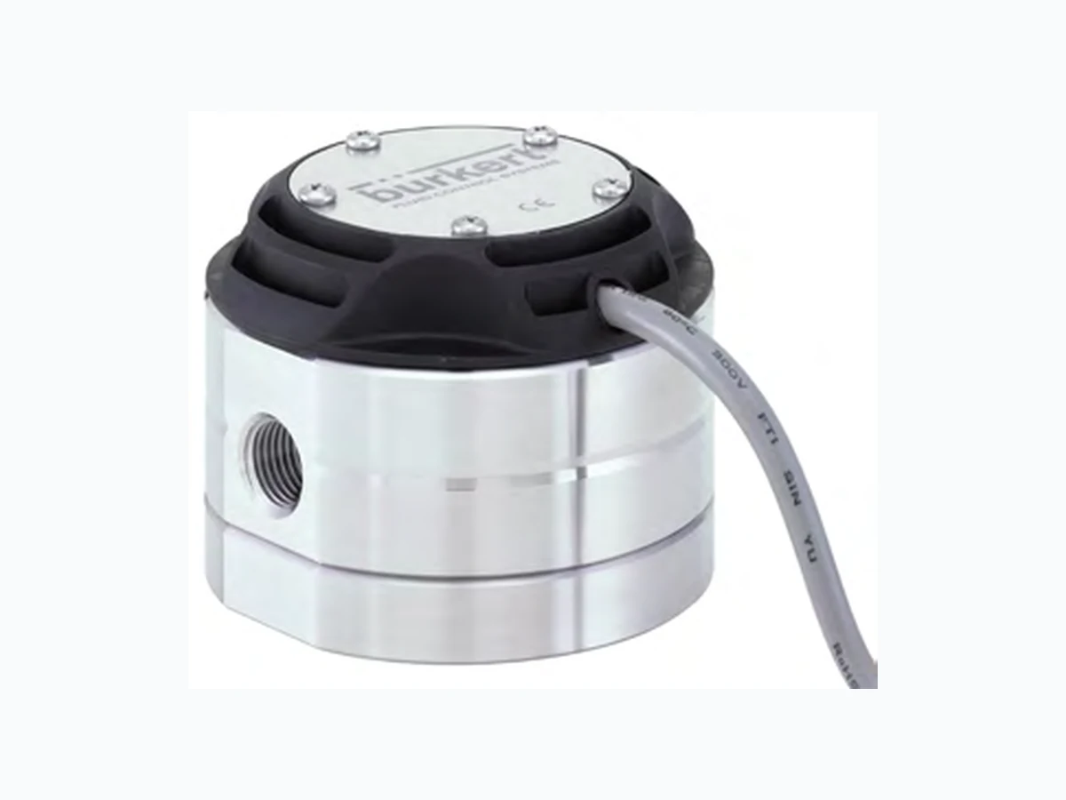
- For highly viscous fluids Value indication, monitoring, transmitting, On/Off control and batch control in combination with different transmitters This sensor is specially designed for measurement or batch control of highly vis- cous fluids like glue, honey or oil. It allows an easy connection to transmitters like types 8025, 8611 and 8619 for more functionality. The design of this low flow sensor is based on the oval rotor principle. This has proven to be a reliable and highly accurate volumetric method of measuring flow. Exceptional repeatability and high accuracy over a wide range of viscosities and flowrates are features of this design. The low pressure drop and high pressure rat- ing make it suitable for gravity and pump (in-line) applications and many others. All sensors provide Open Collector NPN frequency output and frequency output on Reed contact via 1-meter 5-wire cable. Product variants described in the data sheet may differ from the product presentation and description. Type description Can be combined with Type 8077 © Christian Bürkert GmbH & Co. KG, Subject to alteration
2 | 7Visit product website Table of contents 1. General technical data 3 Approvals and conformities 2.2. Standards .... 2.3. Pressure Equipment Directive (PED) .... Device used on a pipe 3. Materials 5 3.2. Material specifications ... 4. Dimensions 5 Product installation 6. Product operation 6 7. Ordering information 7 7.2. Bürkert product filter 7.3. Ordering chart 7.4. Ordering chart accessories ....
3 | 7Visit product website 1. General technical data Product properties Material Make sure the device materials are compatible with the fluid you are using. Further information can be found in chapter “3.1. Bürkert resistApp” on page 5 Further information on the materials can be found in chapter “3.2. Material specifications” on page 5 Non wetted parts Transmitter housing PP (20 % glass fiber) Screw Stainless steel 304 (A2) Tag plate Aluminium Wetted parts Axis Stainless steel 316L (1.4401) Oval gear Stainless steel 316L (1.4401) Sensor body Aluminium, stainless steel 316L (1.4401) Cover Aluminium, stainless steel 316L (1.4401) Seal FEP/PTFE Compatibility With Type
8025 Universal transmitter/batch controller, Type
8611 eCONTROL Universal controller or Type 8619 multiCELL transmitter/Controller Further information can be found in the respective technical data sheets, see data sheets Type 8025 , Type 8611 , Type 8619 for more information. Dimensions Further information can be found in chapter “4. Dimensions” on page 5 Measuring principle Oval gear Type of sensor Hall effect (Transistor output) or Reed contact (Reed switch output) Measuring range 0.5…500 l/h (0.13…132 gph) (depends on the variant) Standard K factor • For flow range 0.5…100 l/h: 1000 pulses/l For flow range 15…500 l/h: 400 pulses/l Performance data Measurement deviation • Standard K factor: ± % of the measured value Specific K factor (directly readable on the label of the product): ± 0.5 % of the measured value Repeatability ≤ 0.03 % of the measured value Electrical data Operating voltage 4.5…24 V DC Current consumption ≤ mA (Hall effect sensor) Output • Hall effect sensor Frequency on open collector, NPN, max. 25 mA 4.5…24 V DC Recommended load: 1.8 KΩ Pull up at 24 V DC Reed contact Frequency Switching voltage: 30 V DC, Max. current: 0.5 A Medium data Fluid temperature • With aluminium body: - 20…+ °C (- 4…+ 176 °F) With stainless steel body: - 20…+ 120 °C (- 4…+ 248 °F) Fluid pressure • With aluminium body: 55 bar (798 PSI) With stainless steel body: 55 bar (798 PSI) Dynamic viscosity η 1 Pa.s. max. (higher on request) Maximum particle size 75 µm To prevent damage from dirt or foreign matter, we strongly recommend the installation of a 75 µm (200 mesh) strainer as close as possible to the inlet side of the meter. Process/Pipe connection & communication Pipe connection Thread ⅛", ¼" (G or NPT) Electrical connection • 5-wire cable m length
4 | 7Visit product website Approvals and conformities Directives CE directive Further information on the CE Directive can be found in chapter “2.2. Standards” on page 4 Pressure equipment directive Complying with article 4, paragraph 1 of 2014/68/EU directive Further information on the pressure equipment directive can be found in chapter “2.3. Pressure Equipment Directive (PED)” on page 4 Environment and installation Ambient temperature Operation and storage: - 15…+ °C (+ 5…+ 140 °F) Relative air humidity ≤ %, without condensation Height above sea level Max. 2000 m Operating condition Continuous Device mobility Fixed Application range Indoor and outdoor Protect the device against electromagnetic interference, ultraviolet rays and, when installed outdoors, against the effects of climatic conditions. Degree of protection IP67, IP66 according to IEC/EN 60529, NEMA 6 according to NEMA 250 Installation category Category I according to UL/EN 61010 Pollution degree Degree 2 according to UL/EN 61010 2. Approvals and conformities 2.1. Conformity In accordance with the Declaration of Conformity, the product is compliant with the EU Directives. 2.2. Standards The applied standards which are used to demonstrate compliance with the EU Directives are listed in the EU-Type Examination Certificate and/or the EU Declaration of Conformity. 2.3. Pressure Equipment Directive (PED) The device conforms to article 4, paragraph 1 of the Pressure Equipment Directive (PED) 2014/68/EU under the following conditions: Device used on a pipe Note: The data in the table is independent of the chemical compatibil ity of the material and the fluid. PS = maximum admissible pressure (in bar), DN = nominal diameter of the pipe Type of fluid Conditions Fluid group 1, article 4, paragraph 1.c.i DN ≤ 25 Fluid group 2, article 4, paragraph 1.c.i DN ≤ 32 or PS*DN ≤ 1000 Fluid group 1, article 4, paragraph 1.c.ii DN ≤ 25 or PS*DN ≤ 2000 Fluid group 2, article 4, paragraph 1.c.ii DN ≤ 200 or PS ≤ 10 or PS*DN ≤ 5000
5 | 7Visit product website 3. Materials 3.1. Bürkert resistApp Bürkert resistApp – Chemical resistance chart You want to ensure the reliability and durability of the materials in your individual application case? Verify your combination of media and materials on our website or in our resistApp. Start chemical resistance check 3.2. Material specifications No. Element Material
1 Tag plate Aluminium
2 Transmitter housing PP (20
% glass fiber) 3 Sensor body Aluminium or stainless steel 316L (1.4401) 4 Rotor and axis Stainless steel 316L (1.4401)
5 Seal FEP/PTFE
6 Cover Aluminium or stainless steel 316L (1.4401) 4. Dimensions Note: Dimensions in mm, unless otherwise stated 7174
6 | 7Visit product website 5. Product installation 5.1. Installation notes Note: The device is not suitable for use in gaseous media and steam. The flowmeter can be installed in any orientation as long as the rotor shafts are always in a horizontal plane. Correct Incorrect The following installation conditions must also be observed: The pipe always has to be filled with fluid at all times near the device. The pipe design must be such that no air bubbles or cavitation can form within the medium near the device at any time. We recommend the installation of a 75 µm strainer as close as possible to the inlet side of the meter, to prevent damage from particles, Air purges can damage the appliance and should therefore be avoided. 6. Product operation 6.1. Measuring principle When liquid flows through the pipe, the rotors turn. This rotation produces a measuring signal in the associated Hall sensor. The rotation frequency of this signal is proportional to the flow velocity of the fluid. The volume of the fluid being transferred in this way is exactly determined through the sensor geometry. A conversion coefficient, specific to each meter size, enables the conversion of this frequency into a flow rate. The standard K factor depending on the meter size is available in the flowmeter’s operating instructions, see Type 8077 . To improve the measurement deviation, a device-specific K factor is given on the device label.
7 | 7Visit product website 7. Ordering information 7.1. Bürkert eShop Bürkert eShop – Easy ordering and quick delivery You want to find your desired Bürkert product or spare part quickly and order directly? Our online shop is available for you 24/7. Sign up and enjoy all the benefits. Order online now 7.2. Bürkert product filter Bürkert product filter – Get quickly to the right product You want to select products comfortably based on your technical requirements? Use the Bürkert product filter and find suitable articles for your application quickly and easily. Try out our product filter 7.3. Ordering chart Measuring range for fluid with viscosity Pipe connection Max. pressure Material Article no. 5 mPa.s < 5 mPa.s Body Rotor Shaft Seal 0.5…100 l/h (0.13…31.70 gph) 2 1.)…100 l/h (0.53…26.4 gph) G ⅛" 55 bar Aluminium Stainless steel Stainless steel FEP/PTFE 567202 bar Stainless steel Stainless steel Stainless steel FEP/PTFE 567203 0.5…100 l/h (0.13…31.70 gph) 2 1.)…100 l/h (0.53…26.4 gph) NPT ⅛" 55 bar Aluminium Stainless steel Stainless steel FEP/PTFE 567204 bar Stainless steel Stainless steel Stainless steel FEP/PTFE 567205 0.5…100 l/h (0.13…31.70 gph) 2 1.)…100 l/h (0.53…26.4 gph) G ¼" 55 bar Stainless steel Stainless steel Stainless steel FEP/PTFE 567206 15…500 l/h (4.00…132 gph) 40…500 l/h (10.56…132 gph) 55 bar Stainless steel Stainless steel Stainless steel FEP/PTFE 567207 15…500 l/h for high viscosity 2.) 55 bar Stainless steel Stainless steel Stainless steel FEP/PTFE 567208 0.5…100 l/h (0.13…31.70 gph) 2 1.)…100 l/h (0.53…26.4 gph) NPT ¼" 55 bar Stainless steel Stainless steel Stainless steel FEP/PTFE 567209 15…500 l/h (4.00…132 gph) 40…500 l/h (10.56…132 gph) 55 bar Stainless steel Stainless steel Stainless steel FEP/PTFE 567210 15…500 l/h for high viscosity 2.) 55 bar Stainless steel Stainless steel Stainless steel FEP/PTFE 567211 1.) For non-lubricating fluids = 6 l/h (e.g. water) 2.) > 1 Pa.s. 7.4. Ordering chart accessories Description Article no. Set with two rotors in stainless steel for measuring range 0.5…100 l/h 567766 Set with two rotors in stainless steel for measuring range 15…500 l/h 567767 Cover made of plastic with Hall sensor and Reed contact 567770 FEP/PTFE seal for measuring range 0.5…100 l/h 567768 FEP/PTFE seal for measuring range 15…500 l/h 567769