
 Download PDF
8001 RHOPOINT
Document overview
- PDF pages: 2
Technical content
Page 1
8000 Series/DIP Reed Relays
DIP R DIP REED R RELAYS DIP REED RELAYS DIP R DIP REED R R EED EED ELAYS ELAYS ELAYS
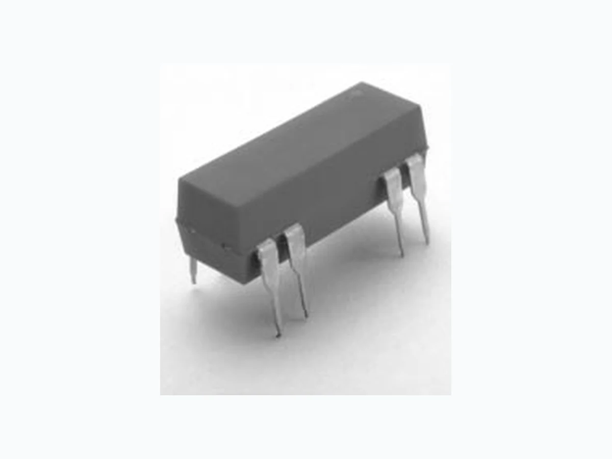
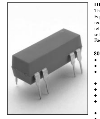
The 8000 Series is ideally suited to the needs of Automated Test Equipment, Instrumentation, Data Acquisition, and Process Control requirements. The specification tables allow you to select the appropriate relay for your particular application. If your requirements differ from the selection options, please consult your local representative or Coto’s Factory to discuss a custom reed relay.
8000 S 8000 SERIES F
F F F FEATURES
8000 SERIES 8000 S 8000 S ERIES EATURES ERIES EATURES EATURES EATURES ERIES u 14 - Pin DIP Industry standard package. u High Insulation Resistance - 1012 Ω offered on most models. u High reliability, hermetically sealed contacts for long life. Proven to 500 million operations. u Contact forms; 1A, 2A, 1B and 1C available. u Surface mount version available. u Molded thermoset body on integral lead frame design. u Optional Electrostatic Shield for reducing capacitive coupling offered on some models. u Coil suppression diode available upon request. u High Voltage Breakdown versions available.
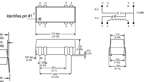
(For Model # 8061)
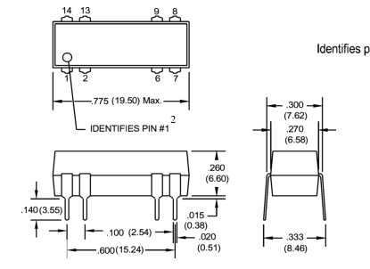
(For Model #’s 8001, 8002, 8021 & 8041)
Dimensions in Inches (Millimeters)
RHOPOINT COMPONENTS LTD Email: components@rhopoint.co.uk Website: www.rhopoint.co.uk
COTO TECHNOLOGY
Page 2
8000 Series/DIP Reed Relays

| Nom. Coil Voltage Max. Coil Voltage Coil Resistance Operate Voltage Release Voltage CONTACT RATINGS Switching Voltage Switching Current Carry Current Contact Rating Life Expectancy-Typical1 Static Contact Resistance (max. init.) Dynamic Contact Resistance (max. init.) RELAY SPECIFICATIONS Insulation Resistance (minimum) Dielectric Strength (minimum) Operate Time - including bounce - Typical Release Time - Typical | +/- 10%, 25° C Must Operate by Must Release by Max DC/Peak AC Resist. Max DC/Peak AC Resist. Max DC/Peak AC Resist. Max DC/Peak AC Resist. Signal Level 1.0V,10mA 50mV, 10mA 0.5V, 50mA at 100 Hz, 1.5 msec Between all Isolated Pins at 100V, 25°C, 40% RH Between Contacts Contacts to Shield Contacts/Shield to Coil At Nominal Coil Voltage, 30 Hz Square Wave No Suppression Diode Suppression | VDC VDC Ω VDC - Max. VDC - Min. Volts Amps Amps Watts x 106 Ops. Ω Ω Ω VDC/peak AC VDC/peak AC VDC/peak AC msec. msec. msec. | 5 12 6.5 15 500 500 3.8 9.6 0.5 1.0 200 0.5 1.0 10 500 0.150 0.200 x 10¹² 300 1500 1500 0.5 0.5 1.0 | 5 12 6.5 15 200 500 3.8 9.6 0.5 1.0 200 0.5 1.0 10 500 0.150 0.200 x 10¹² 300 1500 1500 0.5 0.5 1.0 | 5 12 6.5 15 200 500 3.8 9.6 0.5 1.0 200 0.5 1.0 10 500 0.150 0.200 x 10¹² 300 1500 1500 0.5 0.5 1.0 | 5 12 6.5 15 200 500 3.8 9.6 0.5 1.0 100 0.25 0.5 3 100 0.200 0.250 x 10¹⁰ 200 1500 1500 1.0 0.5 1.5 | 5 12 6.5 15 200 500 3.8 9.6 0.5 1.0 100 0.25 0.5 3 100 0.200 0.250 x 10¹⁰ 200 1500 1500 1.0 0.5 1.5 |
|---|---|---|---|---|---|---|---|
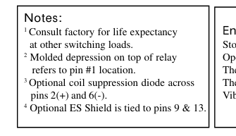
| Top View: Dot stamped on top of relay refers to pin #1 location Grid = .1"x.1" (2.54mm x 2.54mm) | |||||||
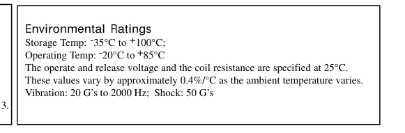
\* For SMD reed relays, maximum reflow soldering temperature is 221°C for one minute. If high temperature solder
(95% Sn / 5% Sb) is used in the relay construction, the temperature limit is 226 °C for one minute.
for through-hole relays (molded or potted), maximum wave solder temperature is 270 °C for 10 secs.