
 Download PDF
WSS AITSEMI
Document overview
- PDF pages: 4
Technical content
Page 1
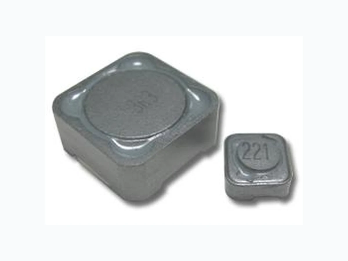
- FEATURE 1. Low core loss for high frequency power application 2. Large terminal surface
- APPLICATION 1. Portable communication equipment, notebook computer
- ORDERING INFORMATION
WSS1203
-1R3
T
PN
Inductance
M: ±20%
- SHAPE AND DIMENSION ●SCHEMATICS AND LAND
PATTERNS(mm)
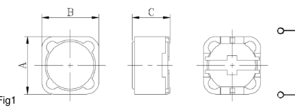
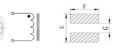
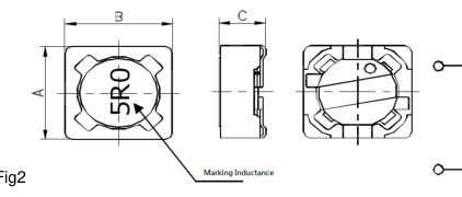
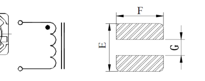
- SPECIFICATION Dimension in mm
| TYPE | A | B | C | E | F | G | Fig |
|---|---|---|---|---|---|---|---|
| WSS1203 | 12.0±0.30 | 12.0±0.30 | 3.90Max | 12.80 | 5.40 | 7.00 | 1 |
| WSS1204 | 12.0±0.30 | 12.0±0.30 | 5.00Max | 12.80 | 5.40 | 7.00 | 1 |
| WSS1205 | 12.0±0.30 | 12.0±0.30 | 6.00Max | 12.80 | 5.40 | 7.00 | 1 |
| WSS1207 | 12.0±0.30 | 12.0±0.30 | 8.00Max | 12.80 | 5.40 | 7.00 | 1 |
| WSS0603 | 6.60±0.30 | 6.20±0.30 | 3.00Max | 8.00 | 1.50 | 4.80 | 2 |
| WSS0605 | 6.60±0.30 | 6.20±0.30 | 5.00Max | 8.00 | 1.50 | 4.80 | 2 |
| WSS0703 | 7.30±0.20 | 7.30±0.20 | 3.50Max | 8.00 | 2.20 | 4.80 | 2 |
| WSS0704 | 7.30±0.20 | 7.30±0.20 | 4.50Max | 8.00 | 2.20 | 4.80 | 2 |
Note1. Measurement frequency of Inductance value : 1.0uH~7.6uH at 7.96MHz, 0.1V, 10uH~1.0mH at 1kHz, 0.1V
WSS1207:1.2uH~7.6uH at 100kHz, 0.1V
Note2. Measurement ambient temperature of L, DCR and IDC : at 25°C Note3. The rated current indicates the current when the inductance decreases to75% over of it’s nominal value or D.C. current when the temperature rising Δt=30°C lower, whichever is lower Note4. Inductance tolerance: M: ±20%
Page 2
- ELECTRICAL CHARACTERISTICS
| PART NUMBER | Inductance (uH) | D.C.R.(ΩMax)/Rated D.C. Current(A) | |||
|---|---|---|---|---|---|
| WSS1203 | WSS1204 | WSS1205 | WSS1207 | ||
| 1R3 | 1.3 | 0.012 / 8.00 | |||
| 2R1 | 2.1 | 0.014 / 7.00 | |||
| 2R2 | 2.2 | 0.015 / 7.00 | |||
| 3R1 | 3.1 | 0.017 / 6.00 | |||
| 3R3 | 3.3 | 0.015 / 5.20 | |||
| 3R9 | 3.9 | 0.015 / 6.50 | |||
| 4R4 | 4.4 | 0.020 / 5.00 | |||
| 4R7 | 4.7 | 0.018 / 5.70 | 0.016 / 6.80 | ||
| 5R6 | 5.6 | 0.037 / 5.00 | |||
| 6R8 | 6.8 | 0.023 / 4.90 | 0.022 / 4.30 | ||
| 7R5 | 7.5 | 0.024 / 4.20 | |||
| 100 | 10 | 0.060 / 3.60 | 0.028 / 4.50 | 0.025 / 4.00 | 0.022 / 5.40 |
| 120 | 12 | 0.038 / 4.00 | 0.027 / 3.50 | 0.025 / 4.90 | |
| 150 | 15 | 0.077 / 3.00 | 0.050 / 3.20 | 0.030 / 3.30 | 0.027 / 4.50 |
| 180 | 18 | 0.057 / 3.10 | 0.034 / 3.00 | 0.040 / 3.90 | |
| 220 | 22 | 0.102 / 2.50 | 0.066 / 2.90 | 0.036 / 2.80 | 0.044 / 3.60 |
| 270 | 27 | 0.080 / 2.80 | 0.051 / 2.30 | 0.046 / 3.40 | |
| 330 | 33 | 0.097 / 2.70 | 0.057 / 2.10 | 0.065 / 3.00 | |
| 390 | 39 | 0.132 / 2.10 | 0.068 / 2.00 | 0.073 / 2.75 | |
| 470 | 47 | 0.150 / 1.90 | 0.075 / 1.80 | 0.100 / 2.50 | |
| 560 | 56 | 0.190 / 1.80 | 0.110 / 1.70 | 0.110 / 2.35 | |
| 680 | 68 | 0.220 / 1.50 | 0.120 / 1.50 | 0.140 / 2.10 | |
| 820 | 82 | 0.260 / 1.30 | 0.140 / 1.40 | 0.160 / 1.95 | |
| 101 | 100 | 0.308 / 1.20 | 0.160 / 1.30 | 0.220 / 1.70 | |
| 121 | 120 | 0.380 / 1.10 | 0.170 / 1.10 | 0.250 / 1.60 | |
| 151 | 150 | 0.530 / 0.95 | 0.230 / 1.00 | 0.280 / 1.42 | |
| 181 | 180 | 0.620 / 0.85 | 0.290 / 0.90 | 0.350 / 1.30 | |
| 221 | 220 | 0.700 / 0.80 | 0.400 / 0.80 | 0.390 / 1.16 | |
| 271 | 270 | 0.876 / 0.60 | 0.460 / 0.75 | 0.560 / 1.06 | |
| 331 | 330 | 0.990 / 0.50 | 0.510 / 0.68 | 0.640 / 0.95 | |
| 391 | 390 | 0.690 / 0.65 | 0.700 / 0.88 | ||
| 471 | 470 | 0.770 / 0.58 | 0.980 / 0.79 | ||
| 561 | 560 | 0.860 / 0.54 | 1.070 / 0.73 | ||
| 681 | 680 | 1.200 / 0.48 | 1.460 / 0.67 | ||
| 821 | 820 | 1.340 / 0.43 | 1.640 / 0.60 | ||
| 102 | 1000 | 1.530 / 0.40 | 1.820 / 0.55 | ||
Page 3
| PART NUMBER | Inductance (uH) | D.C.R.(ΩMax)/Rated D.C. Current(A) | |||
|---|---|---|---|---|---|
| WSS0603 | WSS0605 | WSS0703 | WSS0704 | ||
| 2R2 | 2.2 | 0.025 / 4.32 | 0.020 / 5.00 | ||
| 3R3 | 3.3 | 0.07 / 1.80 | 0.045 / 3.50 | ||
| 3R9 | 3.9 | ||||
| 4R2 | 4.2 | ||||
| 4R7 | 4.7 | 0.09 / 1.50 | 0.055 / 2.00 | 0.051 / 3.00 | |
| 5R6 | 5.6 | ||||
| 6R0 | 6.0 | 0.063 / 1.80 | |||
| 6R8 | 6.8 | ||||
| 7R0 | 7.0 | ||||
| 8R2 | 8.2 | ||||
| 100 | 10 | 0.15 / 1.10 | 0.12 / 1.35 | 0.072 / 1.68 | 0.049 / 1.84 |
| 120 | 12 | 0.20 / 1.00 | 0.13 / 1.22 | 0.098 / 1.52 | 0.058 / 1.71 |
| 150 | 15 | 0.23 / 0.90 | 0.18 / 1.11 | 0.130 / 1.33 | 0.081 / 1.47 |
| 180 | 18 | 0.27 / 0.80 | 0.24 / 1.02 | 0.140 / 1.20 | 0.091 / 1.31 |
| 220 | 22 | 0.34 / 0.74 | 0.27 / 0.91 | 0.190 / 1.07 | 0.110 / 1.23 |
| 270 | 27 | 0.38 / 0.66 | 0.30 / 0.82 | 0.210 / 0.96 | 0.150 / 1.12 |
| 330 | 33 | 0.45 / 0.59 | 0.33 / 0.74 | 0.240 / 0.91 | 0.170 / 0.96 |
| 390 | 39 | 0.49 / 0.54 | 0.37 / 0.69 | 0.320 / 0.77 | 0.230 / 0.91 |
| 470 | 47 | 0.69 / 0.50 | 0.52 / 0.62 | 0.360 / 0.46 | 0.260 / 0.88 |
| 560 | 56 | 0.78 / 0.46 | 0.56 / 0.58 | 0.470 / 0.68 | 0.350 / 0.75 |
| 680 | 68 | 1.07 / 0.42 | 0.63 / 0.51 | 0.520 / 0.61 | 0.380 / 0.69 |
| 820 | 82 | 1.21 / 0.38 | 0.71 / 0.46 | 0.690 / 0.57 | 0.430 / 0.61 |
| 101 | 100 | 1.39 / 0.34 | 1.03 / 0.42 | 0.790 / 0.50 | 0.610 / 0.60 |
| 121 | 120 | 1.90 / 0.31 | 1.15 / 0.38 | 0.890 / 0.49 | 0.660 / 0.52 |
| 151 | 150 | 2.18 / 0.28 | 1.68 / 0.35 | 1.270 / 0.43 | 0.880 / 0.46 |
| 181 | 180 | 2.77 / 0.26 | 1.87 / 0.32 | 1.450 / 0.39 | 0.980 / 0.42 |
| 221 | 220 | 3.12 / 0.23 | 2.08 / 0.29 | 1.650 / 0.35 | 1.170 / 0.36 |
| 271 | 270 | 4.38 / 0.22 | 2.37 / 0.26 | 2.310 / 0.32 | 1.640 / 0.34 |
| 331 | 330 | 4.94 / 0.19 | 2.67 / 0.23 | 2.620 / 0.28 | 1.860 / 0.32 |
| 391 | 390 | 2.94 / 0.22 | 2.940 / 0.26 | 2.850 / 0.29 | |
| 471 | 470 | 3.93 / 0.20 | 4.180 / 0.24 | 3.010 / 0.26 | |
| 561 | 560 | 5.43 / 0.18 | 4.670 / 0.22 | 3.620 / 0.23 | |
| 681 | 680 | 7.32 / 0.17 | 5.730 / 0.19 | 4.630 / 0.22 | |
| 821 | 820 | 8.24 / 0.15 | 6.540 / 0.18 | 5.200 / 0.20 | |
| 102 | 1000 | 9.26 / 0.14 | 9.440 / 0.16 | 6.000 / 0.18 | |
Page 4
- GENERAL CHARACTERISTICS
- Operating temperature range: -40 TO + 85°C (Includes temperature when the coil is heated) 2. External appearance: On visual inspection, the coil has external defects.
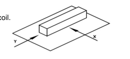
- Terminal strength: After soldering. Between copper plate and terminals of coil. Push in two directions of X.Y withstanding at below conditions. Terminal should not peel off. (refer to figure at right) 0.5kg 4. Insulating resistance: Over 100MΩ at 100V D.C. between coil and core. 5. Dielectric strength: No dielectric breakdown at 100V D.C. for 1 minute between coil and core. 6. Temperature characteristics: Inductance coefficient (0~2,000)x10-6/°C (-25~+80°C). 7. Humidity characteristics(Moisture Resistance): Inductance deviation within ±5%, after 96 hours in 90~95% relative humidity at 40 ±2°C and 1 hour drying under normal condition. 8. Vibration resistance: Inductance deviation within ±5%, after vibration for 1 hour. In each of three
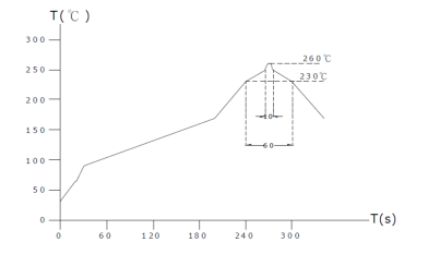
orientations at sweep vibration (10~55~10 Hz) with 1.5mm P-P amplitudes. 9. Shock resistance: Inductance deviation within ±5%, after being dropped once with 981m/s2 (100G) shock attitude upon a rubber block method shock testing machine, in three different orientations. 10. Resistance to Soldering Heat: 260°C, 10 seconds. 11. Storage environment Storage condition: Temperature Range: 10°C ~ 35°C (Generally: 21°C ~ 31°C) Humidity Range: 50% ~ 80% RH (Generally: 65% ~ 75%) Transportation condition: Temperature Range: -35°C ~ 85°C, Humidity Range: 50% ~ 95% RH 12. Use components within 6 months. If 6 months or more have elapsed, check soldarability before use.
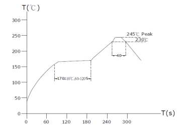
- Reflow profile recommend:
Lead - free heat endurance test
Lead-free the recommended reflow condition