

 Download PDF
IXGA7N60C IXYS
Document overview
- Manufacturer or author: Provided By digicamel.com
- PDF pages: 2
Technical content
Features
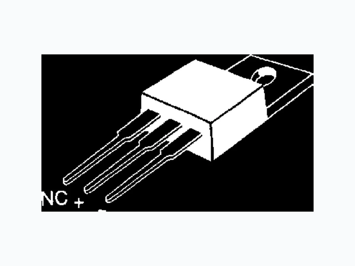
- International standard packages JEDEC TO-263 surface mountable and JEDEC TO-220 AB
- High frequency IGBT
- High current handling capability
- HiPerFAST TM HDMOSTM process
- MOS Gate turn-on - drive simplicity
Applications
- Uninterruptible power supplies (UPS)
- Switched-mode and resonant-mode power supplies
- AC motor speed control
- DC servo and robot drives
- DC choppers Advantages
- High power density
- Suitable for surface mounting
- Very low switching losses for high frequency applications VCES = 600 V IC25 = 1 4 A VCE(sat) = 2.7 V tfi = 4 5 n s G = Gate, C = Collector, E = Emitter, TAB = Collector HiPerFASTTM IGBT LightspeedTM Series IXGA 7N60C IXGP 7N60C G E C (TAB) TO-263 AA (IXGA) G C E TO-220AB (IXGP)
IXYS reserves the right to change limits, test conditions, and dimensions. IXYS MOSFETs and IGBTs are covered by one or more of the following U.S. patents: 4,835,592 4,881,106 5,017,508 5,049,961 5,187,117 5,486,715 6,306,728B1 4,850,072 4,931,844 5,034,796 5,063,307 5,237,481 5,381,025 Symbol Test Conditions Characteristic Values (TJ = 25°C, unless otherwise specified) min. typ. max. gfs IC = IC90; VCE = 10 V, 3 7 S Pulse test, t ≤ 300 µs, duty cycle ≤ 2 % Cies 500 pF Coes VCE = 25 V, VGE = 0 V, f = 1 MHz 50 pF Cres 17 pF Qg 25 nC Qge IC = IC90, VGE = 15 V, VCE = 0.5 VCES 5n C Qgc 10 nC td(on) 9n s tri 10 ns Eon 0.07 mJ td(off) 65 130 ns tfi 45 110 ns Eoff 0.12 0.25 mJ td(on) 10 ns tri 15 ns Eon 0.07 mJ td(off) 120 ns tfi 85 ns Eoff 0.22 mJ RthJC 2.3 K/W RthCK (TO-220) 0.25 K/W Inductive load, TJ = 25°C IC = IC90, VGE = 15 V, L = 300 µH, VCE = 0.8 VCES, RG = Roff = 22 Ω Remarks: Switching times may increase for VCE (Clamp) > 0.8 • VCES, higher TJ or increased R G Inductive load, TJ = 125°C IC = IC90, VGE = 15 V, L = 300 µH VCE = 0.8 VCES, RG = Roff = 22 Ω Remarks: Switching times may increase for VCE (Clamp) > 0.8 • VCES, higher TJ or increased R G TO-220 AB Outline Dim. Millimeter Inches Min. Max. Min. Max. A 12.70 13.97 0.500 0.550 B 14.73 16.00 0.580 0.630 C 9.91 10.66 0.390 0.420 D 3.54 4.08 0.139 0.161 E 5.85 6.85 0.230 0.270 F 2.54 3.18 0.100 0.125 G 1.15 1.65 0.045 0.065 H 2.79 5.84 0.110 0.230 J 0.64 1.01 0.025 0.040 K 2.54 BSC 0.100 BSC M 4.32 4.82 0.170 0.190 N 1.14 1.39 0.045 0.055 Q 0.35 0.56 0.014 0.022 R 2.29 2.79 0.090 0.110 1. Gate 2. Collector 3. Emitter 4. Collector Bottom Side Dim. Millimeter Inches Min. Max. Min. Max. A 4.06 4.83 .160 .190 A1 2.03 2.79 .080 .110 b 0.51 0.99 .020 .039 b2 1.14 1.40 .045 .055 c 0.46 0.74 .018 .029 c2 1.14 1.40 .045 .055 D 8.64 9.65 .340 .380 D1 7.11 8.13 .280 .320 E 9.65 10.29 .380 .405 E1 6.86 8.13 .270 .320 e 2.54 BSC .100 BSC L 14.61 15.88 .575 .625 L1 2.29 2.79 .090 .110 L2 1.02 1.40 .040 .055 L3 1.27 1.78 .050 .070 L4 0 0.38 0 .015 R 0.46 0.74 .018 .029 TO-263 AA Outline Pins: 1 - Gate 2 - Collector 3 - Emitter 4 - Collector Bottom Side Min. Recommended Footprint (Dimensions in inches and mm) IXGA 7N60C IXGP 7N60C