

 Download PDF
7M2-101 COILCRAFT
Document overview
- Manufacturer or author: Provided By digicamel.com
- PDF pages: 4
Technical content
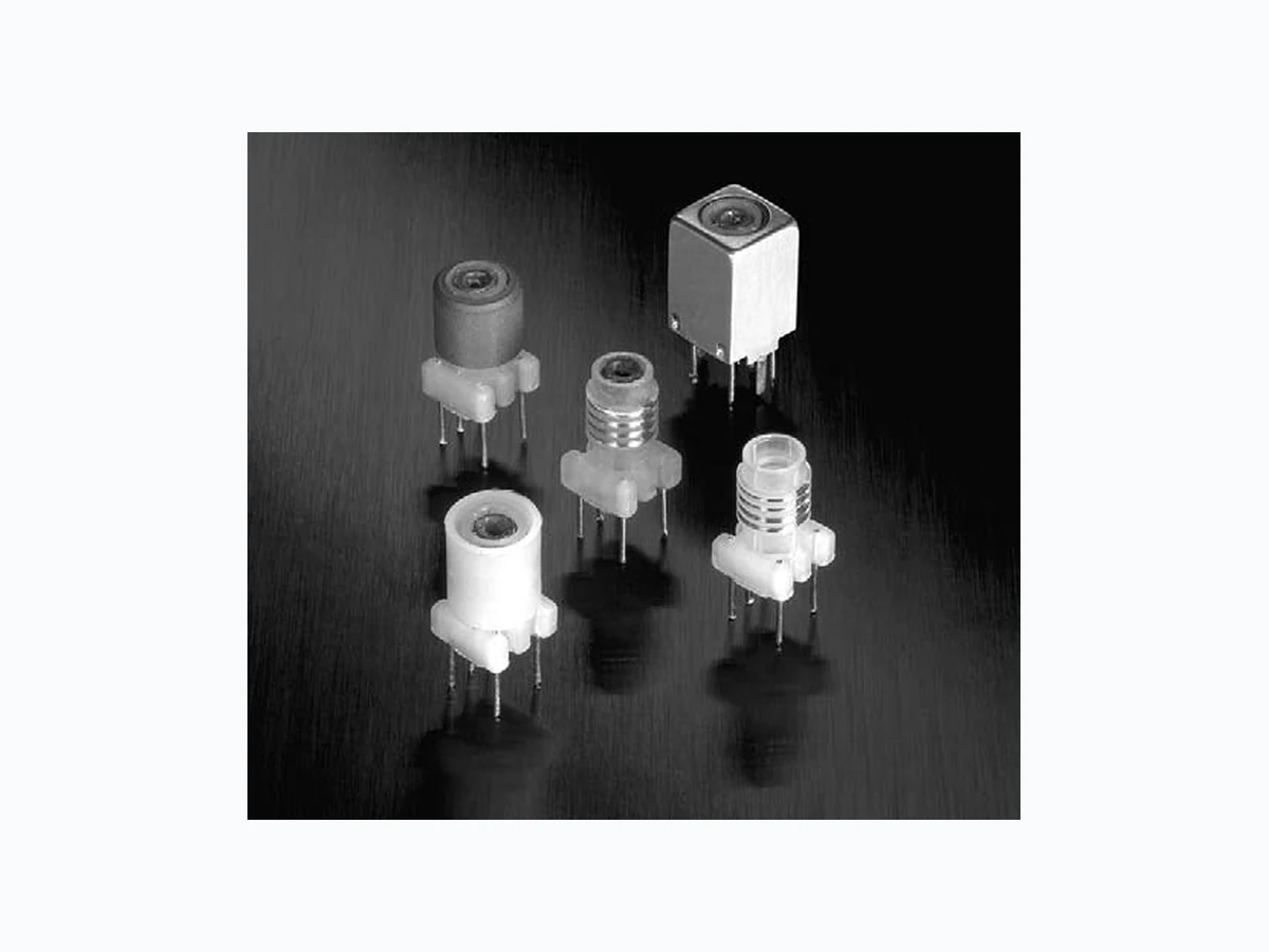
© Coilcraft, Inc. 2007 Specifications subject to change without notice. Please check our website for latest information. “Slot Seven” 7 mm Tunable Inductors Document 112-1 Document 112-1 Revised 02/16/05 321 6 4 0.177 ±0.005 4,50 ±0,13 0.138 .040±0 3,51 ±1,02 0.039 .008±0 0,15 0,010± 0.019 0,48 0.0885 2,248 0.039 0,99 0.059 1,50 0.460 ±0.008 11,68 ±0,20 0,99 0,20± Tab thickness 0.006 .0004±0 sq 0.300 7,62 max sq dia nom ref (5) (2) 0.285 7,24 ref Start Finish Can tab centers Recommended Board Layout Schematic Bottom View Tuning slug These versatile Coilcraft variable inductors operate over a wide range of frequencies. Standard inductance val- ues are available from less than 100 nH to over 250 µH. Custom values can also be provided upon request. Coilcraft “Slot Seven” RF coils come in an international 7 mm package. Their precision-molded slotted bobbins ensure tight tolerances and high stability. A variety of shielding options are offered. “Slot Seven” coils are tuned by means of slotted ferrite tuning cores for easy, positive adjustment. Use the Coilcraft Slot Tuner for a precise fit to the tuning slug. Coilcraft Designer’s Kit M106 contains 39 coils (3 each). To order, please contact Coilcraft or purchase on-line at http://order.coilcraft.com. Weight 7M2 series 1.00 – 1.06 g 7M3 series 1.30 – 1.34 g This product is not RoHS-compliant. Contact Coilcraft for current status or possible alternatives.
© Coilcraft, Inc. 2007 “Slot Seven” 7 mm Tunable Inductors Specifications subject to change without notice. Please check our website for latest information. Document 112-2 Document 112-2 Revised 11/21/02 Frequency (MHz) Q-Factor 1 10 100 -332 -333 -181 -101 -102 -104 -331 Typical Q at L nom — Series 7M2 Series 7M2 — Shielded with Plastic Sleeve Test Q min DCR max Part Number L min (µH) L nom ( µH) L max (µH) frequency @ L nom (Ohms) 7M2-101 0.094 0.100 0.106 25 MHz 27 0.124 7M2-121 0.113 0.120 0.127 25 MHz 27 0.124 7M2-151 0.141 0.150 0.159 25 MHz 30 0.151 7M2-181 0.169 0.180 0.191 25 MHz 30 0.151 7M2-221 0.207 0.220 0.233 25 MHz 35 0.176 7M2-271 0.254 0.270 0.286 25 MHz 35 0.198 7M2-331 0.310 0.330 0.350 25 MHz 40 0.248 7M2-391 0.367 0.390 0.413 25 MHz 40 0.271 7M2-471 0.442 0.470 0.498 25 MHz 40 0.291 7M2-561 0.526 0.560 0.594 25 MHz 40 0.317 7M2-681 0.612 0.680 0.748 25 MHz 40 0.333 7M2-821 0.738 0.820 0.902 25 MHz 45 0.368 7M2-102 0.9 1.0 1.1 25 MHz 45 0.396 7M2-103 9.0 10 11 7.9 MHz 27 2.42 7M2-123 10 12 14 2.5 MHz 20 2.75 7M2-153 13 15 17 2.5 MHz 20 3.71 7M2-183 15 18 21 2.5 MHz 20 4.01 7M2-223 19 22 25 2.5 MHz 20 7.37 7M2-273 23 27 31 2.5 MHz 20 8.48 7M2-333 28 33 38 2.5 MHz 20 13.34 7M2-393 33 39 45 2.5 MHz 20 14.72 7M2-473 40 47 54 2.5 MHz 20 16.42 7M2-563 48 56 64 2.5 MHz 20 17.76 7M2-683 58 68 78 2.5 MHz 20 19.76 7M2-823 70 82 94 2.5 MHz 20 22.01 7M2-104 85 100 115 2.5 MHz 20 24.25 Parts in bold are included in Coilcraft Designer’s Kit M106. Notes: 1. All readings taken on Agilent/HP 4342-A Q Meter. 2. L min is achieved at maximum extension of the core toward PC board. Complete tuning range is reached within the boundaries of the coil form. 3. All specifications are at standard “Q” meter frequencies. L and Q readings change with frequency. 4. Shielded parts have a sleeve insert to protect the winding. 5. Operating temperature range -40°C to +85°C. 6. Electrical specifications at 25°C.
© Coilcraft, Inc. 2007 “Slot Seven” 7 mm Tunable Inductors Specifications subject to change without notice. Please check our website for latest information. Document 112-3 Document 112-3 Revised 11/21/02 Frequency (MHz) Q-Factor 1 10 100 -562 -683 -393 -182 -102 -331 -151 -332 Typical Q at L nom — Series 7M3 Series 7M3 — Shielded with Ferrite Sleeve Test Q min DCR max Part number L min (µH) L nom ( µH) L max (µH) frequency @ L nom (Ohms) 7M3-151 0.128 0.150 0.173 25 MHz 40 0.124 7M3-181 0.153 0.180 0.207 25 MHz 45 0.124 7M3-221 0.187 0.220 0.253 25 MHz 45 0.151 7M3-271 0.230 0.270 0.311 25 MHz 50 0.151 7M3-331 0.281 0.330 0.380 25 MHz 50 0.151 7M3-391 0.332 0.390 0.449 25 MHz 55 0.176 7M3-471 0.400 0.470 0.541 25 MHz 55 0.198 7M3-561 0.476 0.560 0.644 25 MHz 60 0.198 7M3-681 0.544 0.680 0.816 25 MHz 60 0.248 7M3-821 0.656 0.820 0.984 25 MHz 60 0.271 7M3-102 0.8 1.0 1.2 25 MHz 60 0.317 7M3-103 8 10 12 7.9 MHz 35 1.38 7M3-123 9 12 15 2.5 MHz 35 1.49 7M3-153 11 15 19 2.5 MHz 35 1.65 7M3-183 14 18 23 2.5 MHz 35 2.42 7M3-223 17 22 28 2.5 MHz 35 2.75 7M3-273 20 27 34 2.5 MHz 40 3.71 7M3-333 25 33 41 2.5 MHz 40 3.71 7M3-393 29 39 49 2.5 MHz 40 4.01 7M3-473 35 47 59 2.5 MHz 40 7.37 7M3-563 42 56 70 2.5 MHz 40 8.48 7M3-683 51 68 85 2.5 MHz 40 13.34 7M3-823 62 82 103 2.5 MHz 40 14.72 7M3-104 75 100 125 2.5 MHz 40 16.42 7M3-124 90 120 150 2.5 MHz 40 17.76 7M3-154 113 150 188 2.5 MHz 40 19.76 7M3-184 135 180 225 2.5 MHz 40 22.01 7M3-224 165 220 275 2.5 MHz 40 24.25 Parts in bold are included in Coilcraft Designer’s Kit M106. Notes: 1. All readings taken on Agilent/HP 4342-A Q Meter. 2. L min is achieved at maximum extension of the core toward PC board. Complete tuning range is reached within the boundaries of the coil form. 3. All specifications are at standard “Q” meter frequencies. L and Q readings change with frequency. 4. Shielded parts have a sleeve insert to protect the winding. 5. Operating temperature range -40°C to +85°C. 6. Electrical specifications at 25°C.
© Coilcraft, Inc. 2007 “Slot Seven” 7 mm Tunable Inductors Specifications subject to change without notice. Please check our website for latest information. Document 112-4 Document 112-4 Revised 11/21/02 Typical Self Resonant Frequency At nominal inductance 7M2 800 700 600 500 400 300 200 100 Dash Number Frequenc y (MHz) -101 -221 -331 -561 -102 -182 -332 -562 -103 -183 -333 -563 -104 7M3