
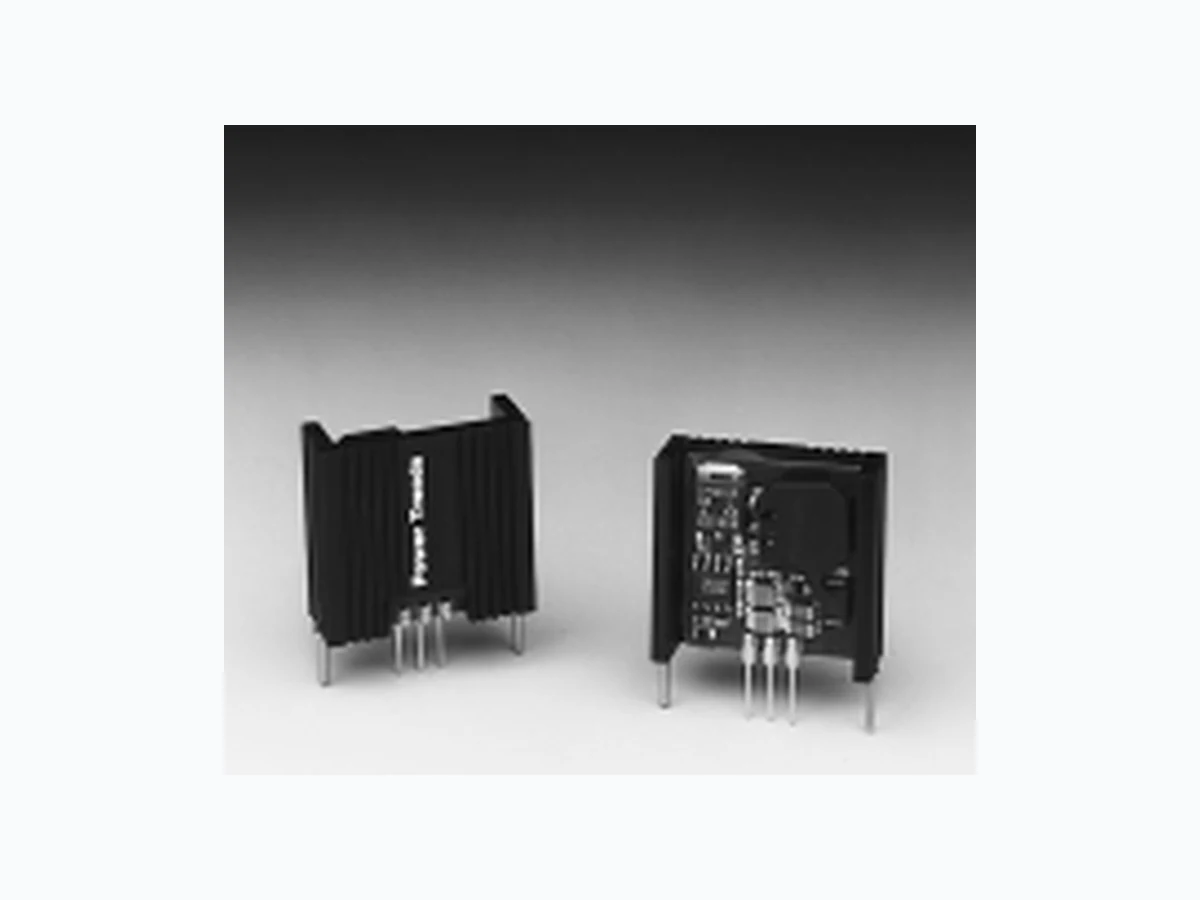
78HT300 TI
Document overview
- Manufacturer or author: Provided By www.digicamel.com(FREE DATASHEET DOWNLOAD SITE)
- PDF pages: 3
Technical content
For assistance or to order, call (800) 531-5782 Power Trends, Inc. 27715 Diehl Road, Warrenville, IL 60555 (800) 531-5782 Fax: (630) 393-6902 http://www.powertrends.com
3 AMP POSITIVE STEP-DOWN
INTEGRATED SWITCHING REGULATOR 78HT300 Series Standard Application C1 = Optional 1µF ceramic C2 = Required 100µF electrolytic Pin-Out Information Pin No. Function 1V in
2 GND
Ordering Information
05 = 5.0 Volts 53 = 5.25 Volts Package Suffix V = Vertical Mount H = Horizontal Mount
- High Efficiency > 80%
- Wide Input Range
- Self-Contained Inductor
- Short-Circuit Protection
- Over-T emperature Protection
- Fast T ransient Response The 78HT300 is a series of wide input voltage, 3 terminal Integrated Switching Regulators (ISRs). Em- ploying a ceramic substrate, these ISRs have a maximum output current of 3A. The output voltage is laser- trimmed for high accuracy. The 78HT300 series regulators have internal short-circuit and over- temperature protection and may be used in a wide variety of applications. Specifications Characteristics 78HT300 SERIES (Ta = 25°C unless noted) Symbols Conditions Min Typ Max Units Output Current I o Over Vin range 0.1* — 3.0 A Input Voltage Range V in Io = 0.1 to 3.0A V o+3 — 28 V Output Voltage Tolerance D Vo Over Vin range — ±1.0 ±2.0 %VoTa = 0°C to +60°C Line Regulation Reg line Over Vin range — ±0.4 ±0.8 %V o Load Regulation Reg load 0.1 £ Io £ 3.0A — ±0.2 ±0.4 %V o Ripple/Noise V n Vin = Vin min, Io = 3.0A — 1 — %Vo Transient Response t tr 50% load change — 100 — µSec (with 100µF output cap) V o over/undershoot 5.0 %V o Efficiency h Vin = 9V, Io = 3.0A — 80 — % Switching Frequency ƒ o Over Vin and Io ranges 700 750 800 kHz Absolute Maximum T a — -40 — +70 °C Operating Temperature Range Recommended Operating T a Free Air Convection, (40-60LFM) -40 — +70** °CTemperature Range Over Vin and Io ranges Thermal Resistance qja Free Air Convection, (40-60LFM) — 35 — °C/W Storage Temperature T s — -40 — +125 °C Mechanical Shock — Per Mil-STD-883D, Method 2002.3 — 500 — G’s Mechanical Vibration — Per Mil-STD-883D, Method 2007.2, —1 0—G ’ s20-2000 Hz, soldered in a PC board Weight — — — 11 — Grams * ISR will operate down to no load with reduced specifications. ** See Thermal Derating chart. Note: The 78HT300 Series requires a 100µF electrolytic or tantalum output capacitor for proper operation in all applications. 78HT300 Vout GNDGND Vin (For dimensions and PC board layout see Package Style 600.) Revised 6/30/98
For assistance or to order, call (800) 531-5782 Power Trends, Inc. 27715 Diehl Road, Warrenville, IL 60555 (800) 531-5782 Fax: (630) 393-6902 http://www.powertrends.com CHARACTERISTIC DATA Note 1: All data listed in the above graphs, except for derating data, has been developed from actual products tested at 25°C. This data is considered typical data for the ISR. Note 2: Thermal derating graphs are developed in free air convection cooling of 40-60 LFM. (See Thermal Application Note) 78HT305_ 5.0 VDC (See Note 1) Efficiency vs Output Current Ripple vs Output Current Power Dissipation vs Output Current Efficiency (%)Ripple (mV)PD (Watts) Iout (A) Iout (A) Iout (A) 78HT300 Series Vin Vin Vin 100 8.0V 10.0V 15.0V 20.0V 28.0V 8.0V 10.0V 15.0V 20.0V 28.0V 0.0 0.5 1.0 1.5 2.0 2.5 3.0 3.5 4.0 8.0V 10.0V 15.0V 20.0V 28.0V Thermal Derating (Ta) (See Note 2) Iout (A) Vin (Volts) 0.0 0.5 1.0 1.5 2.0 2.5 3.0 8 1 21 62 02 42 8 60°C 70°C 85°C 50°C
Texas Instruments and its subsidiaries (TI) reserve the right to make changes to their products or to discontinue any product or service without notice, and advise customers to obtain the latest version of relevant information to verify, before placing orders, that information being relied on is current and complete. All products are sold subject to the terms and conditions of sale supplied at the time of order acknowledgement, including those pertaining to warranty, patent infringement, and limitation of liability. TI warrants performance of its semiconductor products to the specifications applicable at the time of sale in accordance with TI’s standard warranty. Testing and other quality control techniques are utilized to the extent TI deems necessary to support this warranty. Specific testing of all parameters of each device is not necessarily performed, except those mandated by government requirements. CERTAIN APPLICATIONS USING SEMICONDUCTOR PRODUCTS MAY INVOLVE POTENTIAL RISKS OF DEATH, PERSONAL INJURY, OR SEVERE PROPERTY OR ENVIRONMENTAL DAMAGE (“CRITICAL APPLICATIONS”). TI SEMICONDUCTOR PRODUCTS ARE NOT DESIGNED, AUTHORIZED, OR WARRANTED TO BE SUITABLE FOR USE IN LIFE-SUPPORT DEVICES OR SYSTEMS OR OTHER CRITICAL APPLICATIONS. INCLUSION OF TI PRODUCTS IN SUCH APPLICATIONS IS UNDERSTOOD TO BE FULLY AT THE CUSTOMER’S RISK. In order to minimize risks associated with the customer’s applications, adequate design and operating safeguards must be provided by the customer to minimize inherent or procedural hazards. TI assumes no liability for applications assistance or customer product design. TI does not warrant or represent that any license, either express or implied, is granted under any patent right, copyright, mask work right, or other intellectual property right of TI covering or relating to any combination, machine, or process in which such semiconductor products or services might be or are used. TI’s publication of information regarding any third party’s products or services does not constitute TI’s approval, warranty or endorsement thereof. Copyright 1999, Texas Instruments Incorporated