

 Download PDF
788 SCHNEIDER
Document overview
- PDF pages: 4
Technical content
Page 1
Description
Description
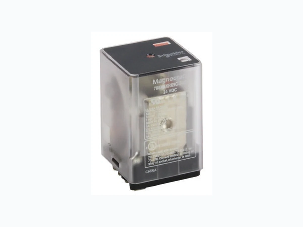
The 788 Series square base, plug-in relays offer clear, full-feature, top flange, and side flange covers as well as optional sockets and accessories.
UL listed when used with proper Magnecraft sockets
| Feature 10 A max. switching current | Benefit Ideal for automation panels and controls |
|---|---|
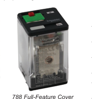
| Clear or full-feature cover options | Full-feature covers include LED indicator and locking test button |
| DPDT and 3PDT contact configurations | Simultaneously control separate circuits |
| Socket mount option | Simplifies installation and maintenance while also allowing the use of protection modules, hold-down clips and other accessories |
| Gold-flashed contacts | Reduces contact oxidation and increases shelf life |
| Mechanical flag indicator | Standard feature displays relay status during testing or operation |
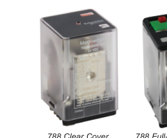
788 Clear Cover
| Contact Rating | Contact Configuration | Nominal Voltage | Coil Resistance (Ω) | Standard Part Number: Clear Cover | Standard Part Number: Clear Cover with LED | Standard Part Number: Flange Mount | Standard Part Number: Full-Feature |
|---|---|---|---|---|---|---|---|
| 10 A | DPDT | 12 Vac 50/60Hz | 16.9 | 788XBXRC-12A | 788XBXRCL-12A | 788XBXRC1-12A | 788XBXRM4L-12A |
| 24 Vac 50/60Hz | 72 | 788XBXRC-24A | 788XBXRCL-24A | 788XBXRC1-24A | 788XBXRM4L-24A | ||
| 120 Vac 50/60Hz | 1700 | 788XBXRC-120A | 788XBXRCL-120A | 788XBXRC1-120A | 788XBXRM4L-120A | ||
| 240 Vac 50/60Hz | 6800 | 788XBXRC-240A | 788XBXRCL-240A | 788XBXRC1-240A | 788XBXRM4L-240A | ||
| 12 Vdc | 120 | 788XBXRC-12D | 788XBXRCL-12D | 788XBXRC1-12D | 788XBXRM4L-12D | ||
| 24 Vdc | 470 | 788XBXRC-24D | 788XBXRCL-24D | 788XBXRC1-24D | 788XBXRM4L-24D | ||
| 48 Vdc | 1800 | 788XBXRC-48D | 788XBXRCL-48D | 788XBXRC1-48D | 788XBXRM4L-48D | ||
| 110 Vdc | 7300 | 788XBXRC-110D | 788XBXRCL-110D | 788XBXRC1-110D | 788XBXRM4L-110D | ||
| 3PDT | 12 Vac 50/60Hz | 16.9 | 788XCXRC-12A | 788XCXRCL-12A | 788XCXRC1-12A | 788XCXRM4L-12A | |
| 24 Vac 50/60Hz | 72 | 788XCXRC-24A | 788XCXRCL-24A | 788XCXRC1-24A | 788XCXRM4L-24A | ||
| 120 Vac 50/60Hz | 1700 | 788XCXRC-120A | 788XCXRCL-120A | 788XCXRC1-120A | 788XCXRM4L-120A | ||
| 240 Vac 50/60Hz | 6800 | 788XCXRC-240A | 788XCXRCL-240A | 788XCXRC1-240A | 788XCXRM4L-240A | ||
| 12 Vdc | 120 | 788XCXRC-12D | 788XCXRCL-12D | 788XCXRC1-12D | 788XCXRM4L-12D | ||
| 24 Vdc | 470 | 788XCXRC-24D | 788XCXRCL-24D | 788XCXRC1-24D | 788XCXRM4L-24D | ||
| 48 Vdc | 1800 | 788XCXRC-48D | 788XCXRCL-48D | 788XCXRC1-48D | 788XCXRM4L-48D | ||
| 110 Vdc | 7300 | 788XCXRC-110D | 788XCXRCL-110D | 788XCXRC1-110D | 788XCXRM4L-110D |
Note: Magnetic blowout versions are also available with an added contact rating of 3 A at 150 Vdc. Please refer to the Part Number Explanation shown below.
Part Number Explanation
Series:
Coil Voltages:
788 = 788 Series
12–240A = 12–240 VAC
Relay
12–110D = 12–110 VDC
Cover Options: C = Clear Cover
DC Switching:
Contact Configuration:
CL = Clear Cover and LED
Blank = None
XBXR = DPDT
C1 = Flange Cover
69 = Magnetic
XCXR = 3PDT
M4L = Locking Push Button
Blowout
and LED
Please contact Customer Service
(Clear Cover
for more information (847-441-2540).
only)
Page 2
Specifications
Specifications
Part Number
788XBXR/XCXR
Contact Characteristics
| Terminal Style | Blade |
|---|---|
| Contact Configuration | DPDT/3PDT |
| Maximum Current | 10 A |
| Contact Materials | Silver Alloy |
| Maximum Switching Voltage | IEC: 250 Vac / 28 Vdc UL/CSA: 300 Vac / 30 Vdc |
| Rated Switching Current at Voltage (Conforming to IEC AC-1 and DC-1) | NO: 10 A at 250 Vac, NC: 5 A at 250 Vac NO: 10 A at 28 Vdc, NC: 5 A at 28 Vdc |
| Rated Switching Current at Voltage (Conforming to UL) | Resistive: 10 A at 277 Vac 50 / 60 Hz, 200k cycles Resistive: 10 A at 30 Vdc, 200k cycles Motor: 1/3 HP at 120 Vac, 6k cycles Motor: 1 HP at 277 Vac, 6k cycles Pilot Duty: B300, 6k cycles |
| Rated Current with Magnetic Blowout (Code 69) | UL: 3 A at 150 Vdc (DPDT only), 6k cycles |
| Minimum Switching Requirement | 10 mA at 17 Vdc |
Coil Characteristics
| Maximum Operating Voltage | 110% (AC / DC) |
|---|---|
| Maximum Pickup Voltage | 85% (AC); 80% (DC) |
| Drop-out Voltage Threshold | 15% (AC); 10% (DC) |
| Average Consumption | 3 VA (AC); 1.4 W (DC) |
General Characteristics
| Electrical Life at Rated Load | 100,000 operations |
| Mechanical Life (Unpowered) | 5,000,000 operations |
| Operating Time (Response Time) | 20 ms |
| Dielectric Strength - Between Coil and Contact (AC) | 2500 V(rms) |
| Dielectric Strength - Between Poles (AC) | 2000 V(rms) |
| Dielectric Strength - Between Open Contacts (AC) | 1500 V(rms) |
| Ambient Air Temperature around the Device - Storage | -40 to +85 °C (-40 to +185 °F) |
| Ambient Air Temperature around the Device - Operation | -40 to +55 °C (-40 to +131 °F) |
| Vibration Resistance - Operational | +/- 1 mm (10–35 Hz) and 3 g-n (35–150 Hz) |
| Shock Resistance | 10 g-n |
| Degree of Protection (Housing Only) | IP 40 |
| Weight | 83 g (2.93 oz) |
| Agency Approvals | UL with socket, UR (E164862), CE, CSA (225619), RoHS |
Note: Actual product performance may vary depending on application and environmental conditions.
Page 3
Dimensions, Wiring Diagrams
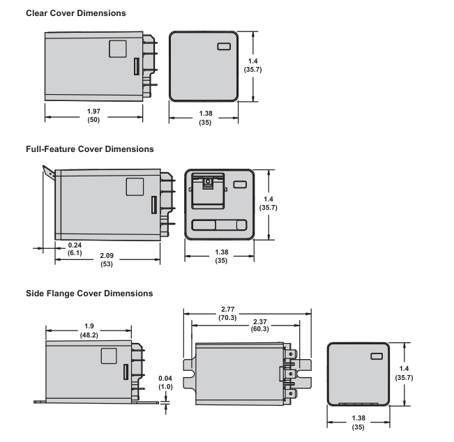
Dimensions — inches (millimeters)
Wiring Diagrams
PDT
DPDT
3PDT
2
1 2 3
3 1
32
32 22
12 22 12
4 5 6
4
5
6
34 24
14
14 24
34
NEMA
IEC
7
7 9
8 9
11
21 31
21 11
A
B
B
A B A1
A2
A1 A2
A2
Page 4
Description
788 Series Accessories
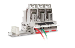
Description
Optional sockets offer customizable, Fingersafe solutions including protection modules, hold-down clips, and ID tags. Sockets are DIN rail and panel mount compatible.
Relay Accessories
| Description | Function | For Use With Relays | Pkg. Min. | Standard Part Number |
|---|---|---|---|---|
| Socket ➊ | DIN mount with elevator terminals | 788XBXR/XCXR | 10 | 70-788EL11-1 |
| Socket ➋ | DIN/Panel mount with screw terminals and clamping plates | 10 | 70-463-1 | |
| Socket ➌ | 0.187 in. Quick Connect terminals with mounting tabs | 10 | 70-124-2 | |
| Socket ➍ | Printed circuit terminals with mounting tabs | 10 | 70-178-1 | |
| Socket ➎ | Printed circuit terminals without mounting tabs | 10 | 70-178-2 |
Socket Accessories
| Description | Function | For Use With Sockets | Coil Voltage | Pkg. Min. | Standard Part Number |
|---|---|---|---|---|---|
| Metal Spring Clip ➊ | Secures relay in socket | 70-788EL11-1, 70-463-1, 70-124-1, 70-178-1, 70-178-2 | – | 10 | 16-1351 |
| Metal Spring Clip ➋ | Secures relay in socket | 70-463-1 | – | 10 | 16-1344 |
| Insulated Coil Bus Jumper System ➌ | Wireless socket connection | 70-788EL11-1 | – | 10 | 16-750/788CBJ-1 |
| Plastic I.D. Tag ➍ | Write-on plastic labels | 70-788EL11-1 | – | 10 | 16-750/788FT-1 |
| Extruded Aluminum DIN Rail, 39.37'' (1000 mm) ➎ | Quick installation and removal of sockets | 70-788EL11-1, 70-463-1 | – | 10 | 16-700DIN |
| DIN Rail End Clip ➎ | Holds sockets firmly in place on DIN rail | – | – | 10 | 16-DCLIP-1 |
| Large Socket Module | MOV Suppressor (Protects from damaging electrical spikes) | 70-788EL11-1 | 24 Vac/Vdc | 10 | 70-ASMM-24 |
| Large Socket Module | Protection Diode (Protects external drive circuitry from inductive voltages) | 250 Vdc | 10 | 70-ASMD-250 | |
| Large Socket Module ➏ | LED Indicator (Provides coil status at a glance) | 110/240 Vac/Vdc | 10 | 70-ASMLG-110/240 | |
| Large Socket Module | RC Suppressor (Snubs back EMF of relay coil) | 110/240 Vac | 10 | 70-ASMR-110/240 |
Note: Use of LED or RC socket module may increase coil power draw by up to 10%.