

 Download PDF
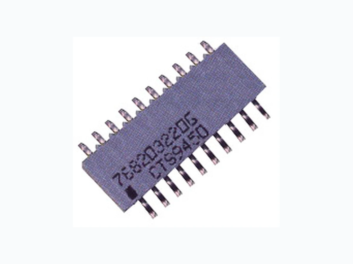
768 CTS
Document overview
- PDF pages: 5
Technical content
Page 1
Features
- Medium Body Design
- Low Profile---Board to Network Clearance of 0.0075”±0.0025”
- Solid Ceramic Construction
- No Internal Dendrite Growth
- Conforms to EIA PDP-100 SOGN-0002
- Packaged in Tape & Reel or Slide Packs
- Application Specific Circuits Are Available
- Compatible With Reflow Solder Process
- RoHS Compliant
Resistance Tolerance: Standard: ±2% or 0.5Ω (whichever is greater) Special: ±0.25% or 0.3Ω (whichever is greater)
Operating Temperature Range: -55°C to +125°C
Temperature Coefficient: Standard: 100Ω to 1 MegΩ 100PPM/°C typical 10Ω to 99Ω ±200PPM/°C typical
Leaded Surface Mount Series 768
Technical Data
Resistance Range: Standard: 10Ω to 1 MegΩ
Dielectric Strength: 100 VAC
Maximum Operating Voltage: 50V not to exceed rated power
Power Rating (Total Network Power):
| 14 Pin | 16 Pin | 20 Pin | |
| @25°C | 2.0w | 2.3w | 3.0w |
| @70°C | 1.3w | 1.5w | 2.0w |
Maximum Resistor Power: (Not to Exceed Total Network Power)
| Schematic | 1 | 3 | 5 | 7 |
| @25°C | 0.15w | 0.30w | 0.15w | 0.15w |
| @70°C | 0.10w | 0.20w | 0.10w | 0.10w |
1 of 5
January 2008
Page 2
Types of Circuits
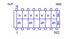
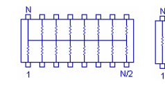
Bussed (Schematic 1) Isolated (Schematic 3) Dual Terminator (Schematic 5) R/2R Ladder (Schematic 7)
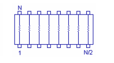
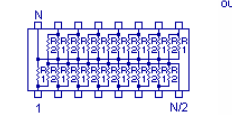
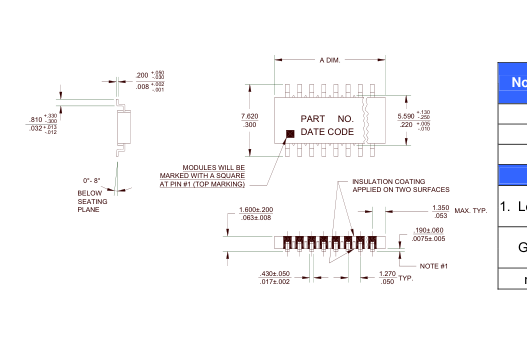
| No. of Pins | "A" Dimension | |
| mm | in. | |
| 14 | 9.91 ±0.25 | 0.390 ±0.010 |
| 16 | 11.18 ±0.25 | 0.440 ±0.010 |
| 20 | 13.70 ±0.25 | 0.540 ±0.010 |
| Notes | ||
| 1. Lead COPLANARITY | mm 0.10 MAX | |
| in. 0.004 | ||
| General Tolerances | mm ±0.25 | |
| in. ±0.010 | ||
| mm & in. DIMENSIONS ARE NOT EQUIVALENT | ||
Land Patterns
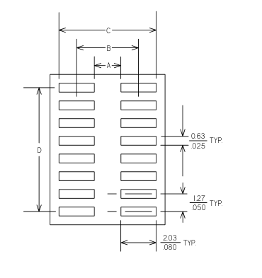
| LEAD COUNT | A | B | C | D | |
| 14P | mm | 5.34 | 7.37 | 9.40 | 7.60 |
| in. | 0.21 | 0.29 | 0.37 | 0.30 | |
| 16P | mm | 5.34 | 7.37 | 9.40 | 8.90 |
| in. | 0.21 | 0.29 | 0.37 | 0.35 | |
| 20P | mm | 5.34 | 7.37 | 9.40 | 11.40 |
| in. | 0.21 | 0.29 | 0.37 | 0.45 | |
January 2008
Page 2 of 5
Page 3
Standard Resistor Values & EIA Code
| Ohms Code | Ohms Code | Ohms Code | Ohms Code | Ohms Code | Ohms Code |
| 0 000X 10 100 12 120 15 150 18 180 22 220 27 270 33 330 39 390 47 470 51 510 56 560 | 68 680 75 750 82 820 100 101 110 111 120 121 150 151 180 181 220 221 270 271 330 331 390 391 | 470 471 510 511 560 561 680 681 820 821 1K 102 1.2K 122 1.5K 152 1.8K 182 2.0K 202 2.2K 222 2.7K 272 | 3.3K 332 3.9K 392 4.7K 472 5.1K 512 5.6K 562 6.8K 682 8.2K 822 10K 103 12K 123 15K 153 18K 183 22K 223 | 27K 273 33K 333 39K 393 47K 473 51K 513 56K 563 68K 683 82K 823 100K 104 120K 124 150K 154 180K 184 | 220K 224 270K 274 330K 334 390K 394 470K 474 510K 514 560K 564 680K 684 820K 824 1M 105 |
Dual Terminator Resistor Values
The Series 768 part number includes the EIA Code value of the Thevenin equivalent resistances of R1 and R2. The Thevenin equivalent resistance is calculated in the following way: The suffix letter relates only to the sequence of variations that equal the same equivalent resistance. Reference Thevenin Equivalent Resistance Chart.
.Req=R1R2/(R1 + R2)
| Example: | |||
| 768205131C | R1=180 Ohms | R2=470 Ohms | Req=130 Ohms |
Pin N/2 is common to R2 and Pin N is common to R1 on CTS Series 768.
Thevenin Equivalent Resistance Chart
| R1 | R2 | Thevenin Equivalent | CTS Code | R1 | R2 | Thevenin Equivalent | CTS Code |
| Ohms | Ohms | ||||||
| 25 | 50 | 17 ohm | 150A | 110 | 220 | 73 ohm | 730A |
| 30 | 50 | 19 ohm | 190A | 118 | 178 | 71 ohm | 710A |
| 30 | 620 | 29 ohm | 290A | 120 | 200 | 75 ohm | 750B |
| 33 | 4.7K | 33 ohm | 330A | 120 | 180 | 72 ohm | 720A |
| 36 | 620 | 34 ohm | 340A | 120 | 120 | 60 ohm | 600B |
| 43 | 620 | 40 ohm | 400A | 150 | 150 | 75 ohm | 750A |
| 68 | 189 | 50 ohm | 500B | 160 | 260 | 99 ohm | 990A |
| 75 | 620 | 67 ohm | 670A | 160 | 240 | 96 ohm | 960A |
| 80 | 220 | 59 ohm | 590A | 160 | 270 | 100 ohm | 101D |
| 81 | 130 | 50 ohm | 500A | 162 | 260 | 100 ohm | 101B |
| 81 | 2.2K | 78 ohm | 780A | 180 | 300 | 113 ohm | 111B |
| 100 | 200 | 67 ohm | 670B | 180 | 470 | 130 ohm | 131C |
| 100 | 430 | 81 ohm | 810A | 180 | 390 | 123 ohm | 121A |
| 100 | 150 | 60 ohm | 600A | 180 | 270 | 108 ohm | 111A |
| 106 | 169 | 65 ohm | 650A | 180 | 220 | 99 ohm | 101A |
(Cont.)
January 2008
Page 3 of 5
Page 4
(Cont.) Thevenin Equivalent Resistance Chart
| R1 | R2 | Thevenin Equivalent | CTS Code | R1 | R2 | Thevenin Equivalent | CTS Code |
| Ohms | Ohms | ||||||
| 200 | 1.5K | 176 ohm | 171D | 560 | 1K | 359 ohm | 361A |
| 220 | 330 | 132 ohm | 131A | 680 | 1K | 405 ohm | 401A |
| 220 | 270 | 121 ohm | 121B | 750 | 750 | 375 ohm | 381A |
| 220 | 220 | 110 ohm | 111D | 750 | 2.3K | 566 ohm | 571A |
| 240 | 170 | 100 ohm | 101C | 1K | 3.3K | 767 ohm | 771A |
| 240 | 620 | 173 ohm | 171C | 1K | 2K | 667 ohm | 671A |
| 250 | 250 | 125 ohm | 131B | 1.1K | 2.2K | 733 ohm | 731A |
| 270 | 470 | 171 ohm | 171A | 1.2K | 1.2K | 600 ohm | 601A |
| 270 | 180 | 108 ohm | 111C | 1.5K | 1.5K | 750 ohm | 751A |
| 271 | 131 | 88 ohm | 880A | 1.5K | 3.3K | 1031 ohm | 102A |
| 330 | 470 | 194 ohm | 191A | 2K | 2K | 1000 ohm | 102B |
| 330 | 680 | 222 ohm | 221A | 2.2K | 5.6K | 1579 ohm | 162A |
| 330 | 390 | 179 ohm | 181A | 2.2K | 4.4K | 1467 ohm | 152A |
| 330 | 220 | 132 ohm | 131D | 2.2K | 3.3K | 1320 ohm | 132A |
| 330 | 330 | 165 ohm | 171B | 3K | 6.2K | 2022 ohm | 202A |
| 360 | 720 | 240 ohm | 241B | 3K | 2K | 1200 ohm | 122A |
| 360 | 600 | 225 ohm | 231A | 3.3K | 4.7K | 1939 ohm | 192A |
| 390 | 620 | 239 ohm | 241A | 3.9K | 3.3K | 1788 ohm | 182A |
| 470 | 1K | 320 ohm | 321A | 4.7K | 22K | 3873 ohm | 392A |
| 470 | 680 | 278 ohm | 281A | 5K | 5K | 2500 ohm | 252A |
| 470 | 940 | 313 ohm | 311A | 6.8K | 22K | 5194 ohm | 522A |
| 500 | 500 | 250 ohm | 251A | 10K | 51K | 8361 ohm | 842A |
| 560 | 910 | 347 ohm | 351A | 50K | 100K | 33,333 ohm | 333A |
- All tolerances +/-2%. 2. Other values available on request. 3. Suffix letter has no significance - assigned in sequential order.
How to Order
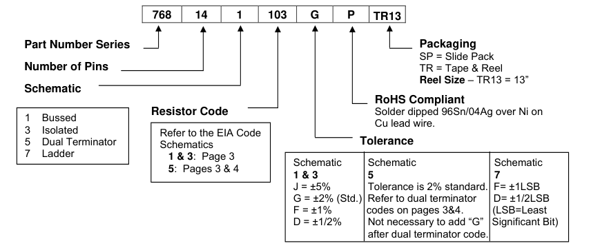
NOTE: No dashes or spaces to appear in part number. Example: 768141103GPTR13
January 2008
Page 4 of 5
Page 5
Packaging
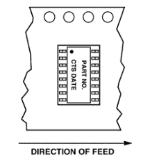
| Tape & Reel | 14P | 16P | 20P |
| Tape width | 24mm | 24mm | 24mm |
| Tape pitch | 12mm | 12mm | 12mm |
| Reel diameter | 13" | 13" | 13" |
| #parts/reel | 2000 | 2000 | 2000 |
| Slide Packs | |||
| Tube length | 20" | 20" | 20" |
| #parts/slide pac | 48 | 43 | 35 |
Environmental Performance Specifications
| Test | Max. % Delta R | Mil. Std. 202 Method | Test Cond. | Test Description |
|---|---|---|---|---|
| Thermal Cycling | 0.25% | 107 | B | 5 cycles, -65°C to +125°C |
| Short Time Overload | 0.25% | 2 1/2 x rated voltage, 5 sec (100V Max.) | ||
| Moisture Resistance | 0.5% | 106 | 240 hours, 0.1 rated load, -10°C to +65°C, 90% RH | |
| Load Humidity | 1.0% | 1000 hours, 0.1 rated load, 70°C, 85-92% RH | ||
| High Temp Exposure | 1.0% | 240 hours, no load, @ 125°C | ||
| Load Life | 1.0% | 108 | F | 2000 hours @ 70°C rated load |
| Resistance to Solder Heat | 0.25% | 30 seconds @ 218°C, dwell | ||
| Mechanical Shock | 0.25% | 213 | I | 100g, 1 msec., 3 shocks each plane |
| Vibration | 0.25% | 204 | D | 20g, 10-2000Hz, 4 hours/plane |
| Terminal Strength | 0.25% | 0.9 Kg. Pull, 30 sec., two 45° bends | ||
| Low Temp Storage | 0.25% | 24 hours @ -65°C, no load | ||
| Low Temp Operation | 0.25% | 45 min @ -65°C, full load | ||
| Flammability | N/A | 94V-0 | ||
| Non-Fungus | Pass | per MIL-STD 810C | ||
| Resistance to Solvents | Pass | Isopropyl alcohol | ||
| Solderability | Pass | RMA Flux, 230°C, 5 seconds dip, 95% coverage | ||
January 2008
Page 5 of 5