
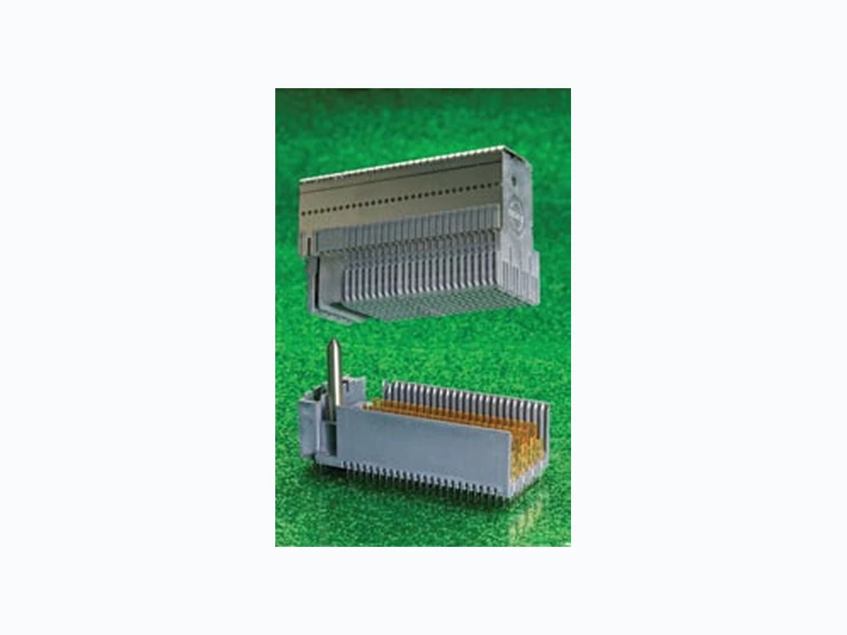
75650 MOLEX
Document overview
- Manufacturer or author: Provided By www.digicamel.com(FREE DATASHEET DOWNLOAD SITE)
- PDF pages: 3
Technical content
Features and speciFications 1.85 by 1.85mm (.073 by .073”) pitch GbX* Backplane connector system in 2, 3, 4 and 5-pair columns 2 and 3 columns: 75650, 75370 differential daughtercard assemblies 75670, 75660 Lite daughtercard assemblies 75676, 75666 Hybrid daughtercard assemblies 75827, 75433 Backplane signal Headers 75861, 75649 Lite Backplane signal Headers 75492, 75331 Backplane power 4 and 5 columns: 75220, 75360 daughtercard assemblies 75420 4-pair Lite daughtercard assemblies 75426 4-pair Hybrid daughtercard assemblies 75235, 75237 Backplane signal Headers 75465 4-pair Lite Backplane signal Header 75341, 75510 Backplane power stand-alone Guide pin Kit: 75234 Features and Benefits Data rates up to 10 Gbps may now be achieved with the GbX 2 and 3-pair column daughtercard and backplane system. The 2 and 3-pair column system completes the GbX product offering, making it a complete solution for high-end telecommunication and datacommunication applications. The GbX connector system provides the speed, density, and low-applied cost required by leading- edge backplane applications. It is especially suited for designs that require future speed upgrades by daughtercard replacement into an existing backplane. With native differential signaling speeds up to 10 Gbps, GbX is well suited for existing and future generations of XAUI (10 Gigabit Attachment Unit Interface) and InfiniBand† based systems, in addition to those based on ATCA‡ (Advanced Telecom Computing Architecture) and OIF (Optical Internetworking Forum) chip protocols. Internetworking and telecommunication equipment engineers will benefit by the GbX connector’s ability to provide not only a high-density, low applied-cost solution in the near term, but also by its electrical performance in upgradeable systems. Speeds of 10 Gbps have been demonstrated with appropriate SERDES (Serializer/ Deserializer) devices and board-material selection. This allows system architects freedom-of- design for faster future systems without the worry of backward compatibility, along with the economy of a common backplane for two generations of equipment. In addition, the GbX Lite Series system provides a complimentary high-density open pin field for cost- effective design of slower-speed circuits along the same stiffener as the standard, high-speed GbX wafers. For more information on Molex’s extensive GbX offering, please visit: www.molex.com/product/backplan/gbx. html. * GbX and VHDM-HSD are registered trademarks of Amphenol Corporation † InfiniBand is a registered trademark of the InfiniBand Trade Association ‡ ATCA is a trademark of the PCI Industrial Manufacturers Group 2 and 3-Pair Columns add to Molex’s GbX Backplane Interconnect System Offering, Delivering Speeds Up To 10 Gbps, High Density (Up to 69 Mated Differential Channels Per Inch) and is Custom Configurable n Up to 69 real differential pairs per linear inch (27 real differential pairs per 10.00mm (.393”) offers high density with more differential pairs per linear inch than VHDM-HSD* n Bifurcated contact beams in daughtercard receptacle provide greater reliability with two points of contact to header pin n Modular daughtercard components with GbX L-Series available with custom, cost-effective receptacle assemblies n Optimized differential pair contacts for easier board trace routing n Data rate options up to 10 Gbps are able to support future daughtercard speed upgrades Top, left to right: 75360, 75220, 75370, 75650. Bottom, left to right: 75237, 75235, 75433, 75827
1.85 by 1.85mm (.073 by .073”) pitch GbX* Backplane connector system in 2, 3, 4 and 5-pair columns
appLications
n Internetworking Equipment: - Servers, Hubs, and Routers n Telecommunications Equipment: - Central Office, Cellular Infrastructure and Multi-platform Service (DSL, Cable Data) systems n Medical Diagnostic Equipment n Test and Measurement Equipment speciFications Reference Information Packaging: Daughtercard Assemblies: Tray Backplane Headers: 2, 4 and 5 Pair- Tray;
3 Pair- Tube
UL File No.: E29179 Designed In: Millimeters Electrical Signal/Shield Contact Current Rating: 1.0A Power Contact Current Rating: 6.0A Contact to Plated-Through-Hole Resistance: 1.0 milliohm max. Power Blade Contact Resistance: 3.0 milliohms max. Dielectric Withstanding Voltage: 750V RMS Insulation Resistance: 1,000 Megohms min. Mechanical Contact Insertion Force: 35.58N (8.00 lb) max. per contact Contact Retention Force: 6.67N (1.50 lb) min. per contact Mating Force: 0.59N (0.13 lb) max. per contact Unmating Force: 0.342N (0.077 lb) min. per contact Durability: 250 cycles max. Physical Housing: Liquid Crystal Polymer, UL 94V-0 Contact: Copper Alloy Plating: Contact Area – 0.76μm (30μ”) Gold (Au) min. Compliant Pin Area – Tin (Sn) or Tin/Lead (SnPb) Underplating – Nickel (Ni) PCB Thickness: 1.60mm (.062”) min. Operating Temperature: -55 to +105°C 2 and 3-pair: Top, left to right: 75370, 75650 Bottom, left to right: 75433, 75827 4 and 5-pair: Top: 75220 Bottom: 75235
Lisle, Illinois 60532 U.S.A. 1-800-78MOLEX amerinfo@molex.com asia pacific north Headquarters Yamato, Kanagawa, Japan 81-46-265-2325 apninfo@molex.com asia pacific south Headquarters Jurong, Singapore 65-6268-6868 fesinfo@molex.com european Headquarters Munich, Germany 49-89-413092-0 eurinfo@molex.com corporate Headquarters 2222 Wellington Ct. Lisle, IL 60532 U.S.A. 630-969-4550 Fax:630-969-1352Visit our website at www.molex.com/product/backplan/gbx.html Order No. USA-250 Rev. 1 Printed in USA/JI/2007.09 ©2007, Molex Daughtercard Assembly *Daughtercards are custom configured. Please visit the Molex Backplane Configurator web site to create a custom daughtercard at: www.molex.com/configurator.html daughtercard assembly 2-pair 3-pair 4-pair 5-pair Signal wafers, power modules, and guide modules sequentially assigned by application 75650-XXXX* (High-speed differential pair signal contacts only; wafer 75651-0001 for reference information only) 75370-XXXX* (High-speed signal contacts only; wafer 75371-0001 for reference information only) 75220-XXXX* (Wafer 75221-0001 for reference information only) 75360-XXXX* (Wafer 75361-0001 for reference information only) Lite wafer blocks, power modules, and guide modules sequentially assigned by application 75670-XXXX* Low-speed signal contacts only, Lite wafer block 75671-0005 for reference information only) 75660-XXXX* Low-speed signal contacts only, Lite wafer block 75661-0005 for reference information only) 75420-XXXX* Low-speed signal contacts only, Lite wafer block 75421-0005 for reference information only) N/A Lite wafer blocks, signal wafers, power modules, and guide modules sequentially assigned by application 75676-XXXX* (High-speed differential pair signal contacts 75651-0001 and low- speed signal contacts 75671-0005 combined in one assembly) 75666-XXXX* (High-speed differential pair signal contacts 75371-0001 and low-speed signal contacts 75661-0005 combined in one assembly) 75426-XXXX* (High-speed differential pair signal contacts 75221-0001 and low-speed signal contacts 75421-0005 combined in one assembly) N/A orderinG inFormation 1.85 by 1.85mm (.073 by .073”) pitch GbX* Backplane connector system in 2, 3, 4 and 5-pair columns 2-pair (4 circuits per column)† 3-pair (6 circuits per column)† 4-pair (8 circuits per column)† 5-pair (10 circuits per column)† Backplane Signal Header Order No. Circuits Order No. Circuits Order No. Circuits Order No. Circuits
5 Column Lite Open 75861-0504 25 75649-0504 40 75465-0505 55 N/A N/A
10 Column Lite Open 75861-0104 50 75649-0104 80 75465-0104 110 N/A N/A
25 Column Lite Open 75861-0204 125 N/A N/A 75465-0204 275 N/A N/A
10 Column Lite Guide Left 75861-2104 50 N/A N/A 75465-2104 110 N/A N/A
25 Column Lite Guide Left 75861-2204 125 N/A N/A 75465-2204 275 N/A N/A
10 Column Lite Guide Right 75861-4104 50 N/A N/A 75465-4104 110 N/A N/A
25 Column Lite Guide Right 75861-4204 125 N/A N/A 75465-4204 275 N/A N/A
5 Column Open N/A N/A 75433-0504 30 N/A N/A N/A N/A
10 Column Open 75827-0104 40 75433-0104 60 75235-0104 80 75237-0104 100
25 Column Open 75827-0204 100 75433-0204 150 75235-0204 200 75237-0204 250
10 Column Guide Left 75827-2104 40 75433-2104 60 75235-2104 80 75237-2104 100
25 Column Guide Left 75827-2204 100 75433-2204 150 75235-2204 200 75237-2204 250
10 Column Guide Right 75827-4104 40 75433-4104 60 75235-4104 80 75237-4104 100
25 Column Guide Right 75827-4204 100 75433-4204 150 75235-4204 200 75237-4204 250
† Multiple keying options are available; contact Molex Inside Sales. Backplane power & Guide components 2-pair 3-pair 4-pair 5-pair order no. circuits order no. circuits order no. circuits order no. circuits Power 75492-1066 4 75331-0444 6 75341-4444 8 75517-7766 10 Stand-Alone Guide Pin Kit 75234-1508 75234-1469 75234-1469 75234-1469 Backplane Power and Guide Components