Download PDF
74HC74 PHILIPS
Document overview
- PDF pages: 22
Technical content
Page 1
INTEGRATED CIRCUITS

Page 2

FEATURES
- Wide supply voltage range from 2.0 to 6.0 V
- Symmetrical output impedance
- High noise immunity
- Low power dissipation
- Balanced propagation delays
- ESD protection: HBM EIA/JESD22-A114-A exceeds 2000 V MM EIA/JESD22-A115-A exceeds 200 V.
QUICK REFERENCE DATA
GND = 0 V; Tamb = 25 °C; tr = tf = 6 ns
GENERAL DESCRIPTION
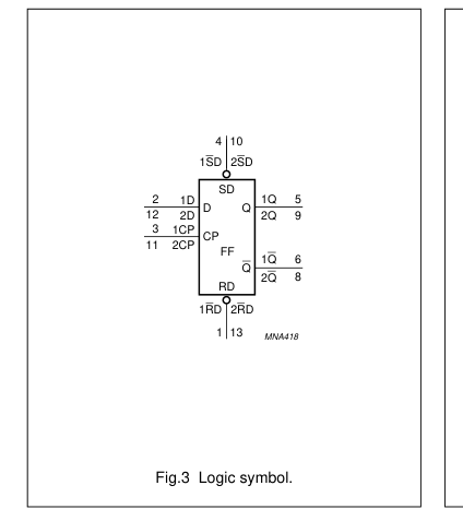
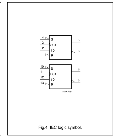
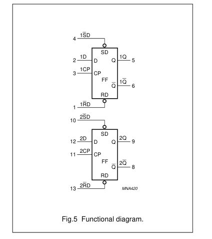
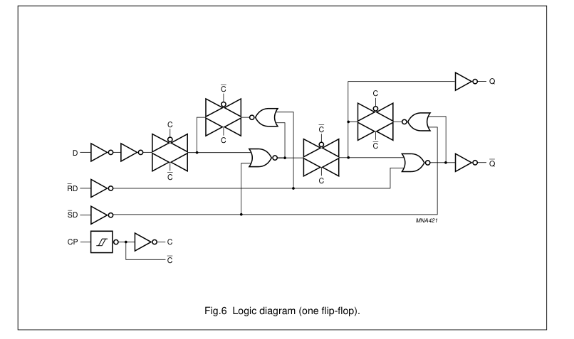
The 74HC/HCT74 is a high-speed Si-gate CMOS device and is pin compatible with low power Schottky TTL (LSTTL). They are specified in compliance with JEDEC standard no. 7A. The 74HC/HCT74 are dual positive-edge triggered, D-type flip-flops with individual data (D) inputs, clock (CP) inputs, set (SD) and reset (RD) inputs; also complementary Q and Q outputs. The set and reset are asynchronous active LOW inputs and operate independently of the clock input. Information on the data input is transferred to the Q output on the LOW-to-HIGH transition of the clock pulse. The D inputs must be stable one set-up time prior to the LOW-to-HIGH clock transition for predictable operation.
Schmitt-trigger action in the clock input makes the circuit highly tolerant to slower clock rise and fall times.
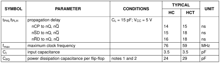
Notes 1. CPD is used to determine the dynamic power dissipation (PD in µW). PD = CPD × VCC2 × fi × N + Σ(CL × VCC2 × fo) where: fi = input frequency in MHz; fo = output frequency in MHz; CL = output load capacitance in pF; VCC = supply voltage in Volts; N = total load switching outputs; Σ(CL × VCC2 × fo) = sum of the outputs. 2. For 74HC74 the condition is VI = GND to VCC. For 74HCT74 the condition is VI = GND to VCC − 1.5 V.
Page 3

FUNCTION TABLES
Table 1 See note 1
| INPUT | OUTPUT | ||||
| SD | RD | CP | D | Q | Q |
| L | H | X | X | H | L |
| H | L | X | X | L | H |
| L | L | X | X | H | H |
Table 2 See note 1
| INPUT | OUTPUT | ||||
| SD | RD | CP | D | Qn+1 | Qn+1 |
| H | H | ↑ | L | L | H |
| H | H | ↑ | H | H | L |
Note 1. H = HIGH voltage level; L = LOW voltage level; X = don’t care; ↑ = LOW-to-HIGH CP transition; Qn+1 = state after the next LOW-to-HIGH CP transition.
ORDERING INFORMATION
| TYPE NUMBER | PACKAGE | ||||
|---|---|---|---|---|---|
| TEMPERATURE RANGE | PINS | PACKAGE | MATERIAL | CODE | |
| 74HC74N | −40 to +125 °C | 14 | DIP14 | plastic | SOT27-1 |
| 74HCT74N | −40 to +125 °C | 14 | DIP14 | plastic | SOT27-1 |
| 74HC74D | −40 to +125 °C | 14 | SO14 | plastic | SOT108-1 |
| 74HCT74D | −40 to +125 °C | 14 | SO14 | plastic | SOT108-1 |
| 74HC74DB | −40 to +125 °C | 14 | SSOP14 | plastic | SOT337-1 |
| 74HCT74DB | −40 to +125 °C | 14 | SSOP14 | plastic | SOT337-1 |
| 74HC74PW | −40 to +125 °C | 14 | TSSOP14 | plastic | SOT402-1 |
| 74HCT74PW | −40 to +125 °C | 14 | TSSOP14 | plastic | SOT402-1 |
| 74HC74BQ | −40 to +125 °C | 14 | DHVQFN14 | plastic | SOT762-1 |
| 74HCT74BQ | −40 to +125 °C | 14 | DHVQFN14 | plastic | SOT762-1 |
Page 4

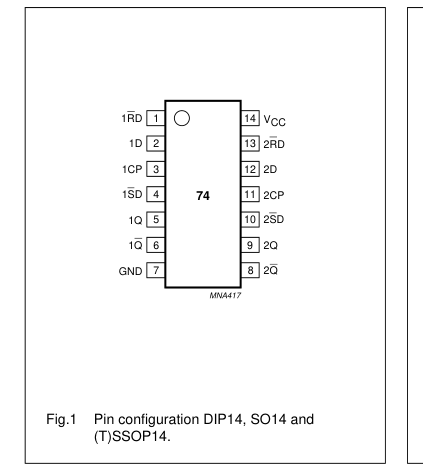
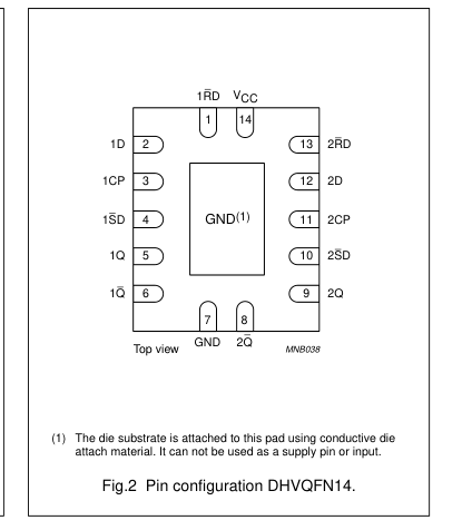
PINNING
| PIN | SYMBOL | DESCRIPTION |
|---|---|---|
| 1 | 1RD | asynchronous reset-direct input (active LOW) |
| 2 | 1D | data input |
| 3 | 1CP | clock input (LOW-to-HIGH, edge-triggered) |
| 4 | 1SD | asynchronous set-direct input (active LOW) |
| 5 | 1Q | true flip-flop output |
| 6 | 1Q | complement flip-flop output |
| 7 | GND | ground (0 V) |
| 8 | 2Q | complement flip-flop output |
| 9 | 2Q | true flip-flop output |
| 10 | 2SD | asynchronous set-direct input (active LOW) |
| 11 | 2CP | clock input (LOW-to-HIGH, edge-triggered) |
| 12 | 2D | data input |
| 13 | 2RD | asynchronous reset-direct input (active LOW) |
| 14 | V CC | positive supply voltage |
Page 5

Page 6
74HC74; 74HCT74
positive-edge trigger
Page 7
74HC74; 74HCT74
positive-edge trigger
RECOMMENDED OPERATING CONDITIONS
| SYMBOL | PARAMETER | CONDITIONS | 74HC74 | 74HCT74 | UNIT | ||||
|---|---|---|---|---|---|---|---|---|---|
| MIN. | TYP. | MAX. | MIN. | TYP. | MAX. | ||||
| V CC | supply voltage | 2.0 | 5.0 | 6.0 | 4.5 | 5.0 | 5.5 | V | |
| V I | input voltage | 0 | − | V CC | 0 | − | V CC | V | |
| V O | output voltage | 0 | − | V CC | 0 | − | V CC | V | |
| T amb | operating ambient temperature | −40 | +25 | +125 | −40 | +25 | +125 | °C | |
| t, t r f | input rise and fall times | V = 2.0 V CC | − | − | 1000 | − | − | 500 | ns |
| V = 4.5 V CC | − | 6.0 | 500 | − | 6.0 | 500 | ns | ||
| V = 6.0 V CC | − | − | 400 | − | − | 500 | ns | ||
LIMITING VALUES
In accordance with the Absolute Maximum Rating System (IEC 60134); voltages are referenced to GND (ground = 0 V).
| SYMBOL | PARAMETER | CONDITIONS | MIN. | MAX. | UNIT |
|---|---|---|---|---|---|
| V CC | supply voltage | −0.5 | +7.0 | V | |
| I IK | input diode current | V < −0.5 V or V > V + 0.5 V; I I CC note 1 | − | ±20 | mA |
| I OK | output diode current | V < −0.5 V or V > V + 0.5 V; O O CC note 1 | − | ±20 | mA |
| I O | output source or sink current | −0.5 V < V < V + 0.5 V; note 1 O CC | − | ±25 | mA |
| I , I CC GND | V or GND current CC | − | ±100 | mA | |
| T stg | storage temperature | −65 | +150 | °C | |
| P tot | power dissipation | T = −40 to +125 °C; note 2 amb | − | 500 | mW |
Notes 1. The input and output voltage ratings may be exceeded if the input and output current ratings are observed. 2. For SO14 packages: above 70 °C derate linearly with 8 mW/K. For SSOP14 and TSSOP14 packages: above 60 °C derate linearly with 5.5 mW/K. For DHVQFN14 packages: above 60 °C derate linearly with 4.5 mW/K. For DIP14 packages: above 70 °C derate linearly with 12 mW/K.
Page 8
74HC74; 74HCT74
positive-edge trigger
DC CHARACTERISTICS
Family 74HC At recommended operating conditions; voltages are referenced to GND (ground = 0 V).
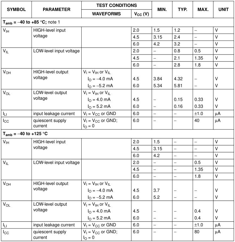
Note 1. All typical values are measured at Tamb = 25 °C.
Page 9
74HC74; 74HCT74
positive-edge trigger
Family 74HCT At recommended operating conditions; voltages are referenced to GND (ground = 0 V).
| SYMBOL | PARAMETER | TEST CONDITIONS | MIN. | TYP. | MAX. | UNIT | |
|---|---|---|---|---|---|---|---|
| WAVEFORMS | V (V) CC | ||||||
| T = −40 to +85 °C; note 1 amb | |||||||
| V IH | HIGH-level input voltage | 4.5 to 5.5 | 2.0 | 1.6 | − | V | |
| V IL | LOW-level input voltage | 4.5 to 5.5 | − | 1.2 | 0.8 | V | |
| V OH | HIGH-level output voltage | V = V or V IL; I IH I = −4.0 mA O | 4.5 | 3.84 | 4.32 | − | V |
| V OL | LOW-level output voltage | V = V or V IL; I IH I = 4.0 mA O | 4.5 | 0.33 | 0.15 | − | V |
| I LI | input leakage current | V = V or GND I CC | 5.5 | − | − | ±1.0 | µA |
| I CC | quiescent supply current | V = V or GND; I CC I = 0 O | 5.5 | − | − | 40 | µA |
| ∆I CC | additional quiescent supply current per input | V = V −2.1 V other I CC inputs at V or GND; CC I = 0 O | 4.5 to 5.5 | − | 100 | 450 | µA |
| T = −40 to +125 °C amb | |||||||
| V IH | HIGH-level input voltage | 4.5 to 5.5 | 2.0 | − | − | V | |
| V IL | LOW-level input voltage | 4.5 to 5.5 | − | − | 0.8 | V | |
| V OH | HIGH-level output voltage | V = V or V IL; I IH I = −4.0 mA O | 4.5 | 3.7 | − | − | V |
| V OL | LOW-level output voltage | V = V or V IL; I IH I = 4.0 mA O | 4.5 | − | − | 0.4 | V |
| I LI | input leakage current | V = V or GND I CC | 5.5 | − | − | ±1.0 | µA |
| I CC | quiescent supply current | V = V or GND; I CC I = 0 O | 5.5 | − | − | 80 | µA |
| ∆I CC | additional quiescent supply current per input | V = V −2.1 V other I CC inputs at V or GND; CC I = 0 O | 4.5 to 5.5 | − | − | 490 | µA |
Note 1. All typical values are measured at Tamb = 25 °C.
Remark to HCT types The value of additional quiescent supply current (∆ICC) for a unit load of 1 is given here. To determine ∆ICC per input, multiply this value by the unit load coefficient shown in the table.
| INPUT | UNIT LOAD COEFFICIENT |
|---|---|
| nD | 0.70 |
| nRD | 0.70 |
| nSD | 0.80 |
| nCP | 0.80 |
Page 10
74HC74; 74HCT74
positive-edge trigger
AC CHARACTERISTICS
Family 74HC GND = 0 V; tr = tf = 6 ns; CL = 50 pF.
| SYMBOL | PARAMETER | TEST CONDITIONS | MIN. | TYP. | MAX. | UNIT | |
|---|---|---|---|---|---|---|---|
| WAVEFORMS | V (V) CC | ||||||
| T = −40 to +85 °C amb | |||||||
| t /t PHL PLH | propagation delay nCP to nQ, nQ | see Fig.7 | 2.0 | − | 47 | 220 | ns |
| 4.5 | − | 17 | 44 | ns | |||
| 6.0 | − | 14 | 37 | ns | |||
| propagation delay nSD to nQ, nQ | see Fig.8 | 2.0 | − | 50 | 250 | ns | |
| 4.5 | − | 18 | 50 | ns | |||
| 6.0 | − | 14 | 43 | ns | |||
| propagation delay nRD to nQ, nQ | see Fig.8 | 2.0 | − | 52 | 250 | ns | |
| 4.5 | − | 19 | 50 | ns | |||
| 6.0 | − | 15 | 43 | ns | |||
| t /t THL TLH | output transition time | see Fig.7 | 2.0 | − | 19 | 95 | ns |
| 4.5 | − | 7 | 19 | ns | |||
| 6.0 | − | 6 | 16 | ns | |||
| t W | clock pulse width HIGH or LOW | see Fig.7 | 2.0 | 100 | 19 | − | ns |
| 4.5 | 20 | 7 | − | ns | |||
| 6.0 | 17 | 6 | − | ns | |||
| set or reset pulse width LOW | see Fig.8 | 2.0 | 100 | 19 | − | ns | |
| 4.5 | 20 | 7 | − | ns | |||
| 6.0 | 17 | 6 | − | ns | |||
| t rem | removal time set or reset | see Fig.8 | 2.0 | 40 | 3 | − | ns |
| 4.5 | 8 | 1 | − | ns | |||
| 6.0 | 7 | 1 | − | ns | |||
| t su | set-up time nD to nCP | see Fig.7 | 2.0 | 75 | 6 | − | ns |
| 4.5 | 15 | 2 | − | ns | |||
| 6.0 | 13 | 2 | − | ns | |||
| t h | hold time nCP to nD | see Fig.7 | 2.0 | 3 | −6 | − | ns |
| 4.5 | 3 | −2 | − | ns | |||
| 6.0 | 3 | −2 | − | ns | |||
| f max | maximum clock pulse frequency | see Fig.7 | 2.0 | 4.8 | 23 | − | MHz |
| 4.5 | 24 | 69 | − | MHz | |||
| 6.0 | 28 | 82 | − | MHz | |||
Page 11
74HC74; 74HCT74
positive-edge trigger
| SYMBOL | PARAMETER | TEST CONDITIONS | MIN. | TYP. | MAX. | UNIT | |
|---|---|---|---|---|---|---|---|
| WAVEFORMS | V (V) CC | ||||||
| T = −40 to +125 °C amb | |||||||
| t /t PHL PLH | propagation delay nCP to nQ, nQ | see Fig.7 | 2.0 | − | − | 265 | ns |
| 4.5 | − | − | 53 | ns | |||
| 6.0 | − | − | 45 | ns | |||
| propagation delay nSD to nQ, nQ | see Fig.8 | 2.0 | − | − | 300 | ns | |
| 4.5 | − | − | 60 | ns | |||
| 6.0 | − | − | 51 | ns | |||
| propagation delay nRD to nQ, nQ | see Fig.8 | 2.0 | − | − | 300 | ns | |
| 4.5 | − | − | 60 | ns | |||
| 6.0 | − | − | 51 | ns | |||
| t /t THL TLH | output transition time | see Fig.7 | 2.0 | − | − | 110 | ns |
| 4.5 | − | − | 22 | ns | |||
| 6.0 | − | − | 19 | ns | |||
| t W | clock pulse width HIGH or LOW | see Fig.7 | 2.0 | 120 | − | − | ns |
| 4.5 | 24 | − | − | ns | |||
| 6.0 | 20 | − | − | ns | |||
| t W | set or reset pulse width LOW | see Fig.8 | 2.0 | 120 | − | − | ns |
| 4.5 | 24 | − | − | ns | |||
| 6.0 | 20 | − | − | ns | |||
| t rem | removal time set or reset | see Fig.8 | 2.0 | 45 | − | − | ns |
| 4.5 | 9 | − | − | ns | |||
| 6.0 | 8 | − | − | ns | |||
| t su | set-up time nD to nCP | see Fig.7 | 2.0 | 90 | − | − | ns |
| 4.5 | 18 | − | − | ns | |||
| 6.0 | 15 | − | − | ns | |||
| t h | hold time nCP to nD | see Fig.7 | 2.0 | 3 | − | − | ns |
| 4.5 | 3 | − | − | ns | |||
| 6.0 | 3 | − | − | ns | |||
| f max | maximum clock pulse frequency | see Fig.7 | 2.0 | 4.0 | − | − | MHz |
| 4.5 | 20 | − | − | MHz | |||
| 6.0 | 24 | − | − | MHz | |||
Page 12
74HC74; 74HCT74
positive-edge trigger
Family 74HCT GND = 0 V; tr = tf = 6 ns; CL = 50 pF.
| SYMBOL | PARAMETER | TEST CONDITIONS | MIN. | TYP. | MAX. | UNIT | |
|---|---|---|---|---|---|---|---|
| WAVEFORMS | V (V) CC | ||||||
| T = −40 to +85 °C amb | |||||||
| t /t PHL PLH | propagation delay nCP to nQ, nQ | see Fig.7 | 4.5 | − | 18 | 44 | ns |
| propagation delay nSD to nQ, nQ | see Fig.8 | 4.5 | − | 23 | 50 | ns | |
| propagation delay nRD to nQ, nQ | see Fig.8 | 4.5 | − | 24 | 50 | ns | |
| t /t THL TLH | output transition time | see Fig.7 | 4.5 | − | 7 | 19 | ns |
| t W | clock pulse width HIGH or LOW | see Fig.7 | 4.5 | 23 | 9 | − | ns |
| set or reset pulse width LOW | see Fig.8 | 4.5 | 20 | 9 | − | ns | |
| t rem | removal time set or reset | see Fig.8 | 4.5 | 8 | 1 | − | ns |
| t su | set-up time nD to nCP | see Fig.7 | 4.5 | 15 | 5 | − | ns |
| t h | hold time nCP to nD | see Fig.7 | 4.5 | +3 | −3 | − | ns |
| f max | maximum clock pulse frequency | see Fig.7 | 4.5 | 22 | 54 | − | MHz |
| T = −40 to +125 °C amb | |||||||
| t /t PHL PLH | propagation delay nCP to nQ, nQ | see Fig.7 | 4.5 | − | − | 53 | ns |
| propagation delay nSD to nQ, nQ | see Fig.8 | 4.5 | − | − | 60 | ns | |
| propagation delay nRD to nQ, nQ | see Fig.8 | 4.5 | − | − | 60 | ns | |
| t /t THL TLH | output transition time | see Fig.7 | 4.5 | − | − | 22 | ns |
| t W | clock pulse width HIGH or LOW | see Fig.7 | 4.5 | 27 | − | − | ns |
| set or reset pulse width LOW | see Fig.8 | 4.5 | 24 | − | − | ns | |
| t rem | removal time set or reset | see Fig.8 | 4.5 | 9 | − | − | ns |
| t su | set-up time nD to nCP | see Fig.7 | 4.5 | 18 | − | − | ns |
| t h | hold time nCP to nD | see Fig.7 | 4.5 | 3 | − | − | ns |
| f max | maximum clock pulse frequency | see Fig.7 | 4.5 | 18 | − | − | MHz |
Page 13
74HC74; 74HCT74
positive-edge trigger
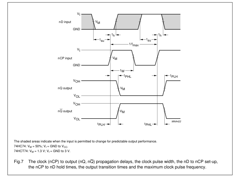
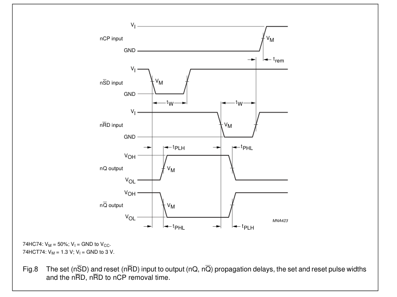
AC WAVEFORMS
Page 14
74HC74; 74HCT74
positive-edge trigger
Page 15
74HC74; 74HCT74
positive-edge trigger
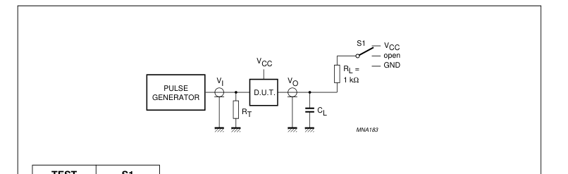
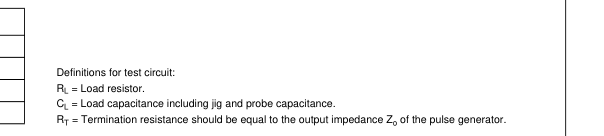
| TEST | S1 |
| t PZH | GND |
| t PZL | V CC |
| t PHZ | GND |
| t PLZ | V CC |
Fig.9 Load circuitry for switching times.
Page 16
74HC74; 74HCT74
positive-edge trigger
PACKAGE OUTLINES
DIP14: plastic dual in-line package; 14 leads (300 mil)
SOT27-1
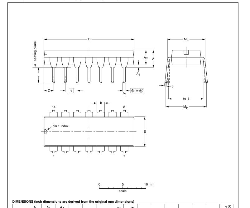

Note 1. Plastic or metal protrusions of 0.25 mm (0.01 inch) maximum per side are not included.
| OUTLINE VERSION | REFERENCES | EUROPEAN PROJECTION | ISSUE DATE | ||||
| IEC | JEDEC | JEITA | |||||
| SOT27-1 | 050G04 | MO-001 | SC-501-14 | 99-12-27 03-02-13 | |||
Page 17

SO14: plastic small outline package; 14 leads; body width 3.9 mm
SOT108-1
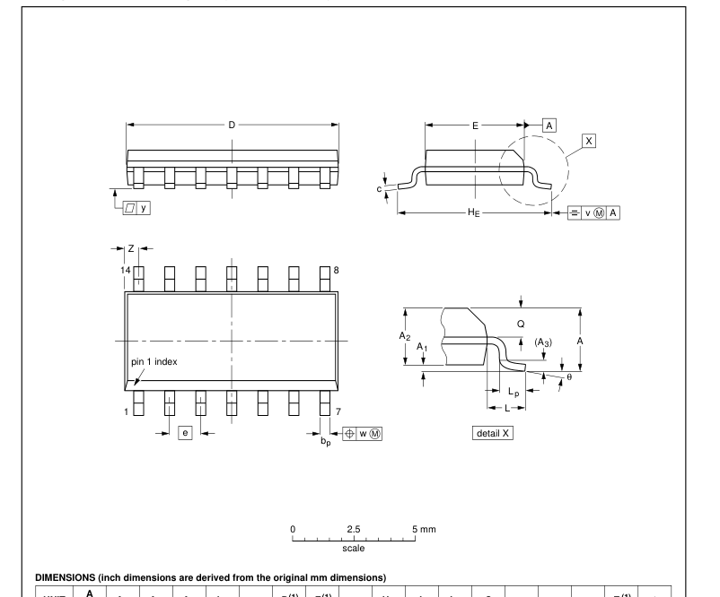

Note 1. Plastic or metal protrusions of 0.15 mm (0.006 inch) maximum per side are not included.
| OUTLINE VERSION | REFERENCES | EUROPEAN PROJECTION | ISSUE DATE | ||||
| IEC | JEDEC | JEITA | |||||
| SOT108-1 | 076E06 | MS-012 | 99-12-27 03-02-19 | ||||
Page 18
74HC74; 74HCT74
positive-edge trigger
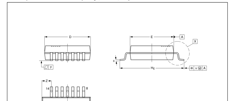
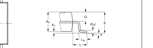
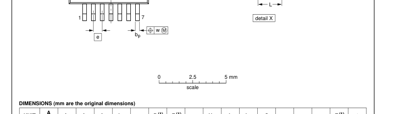
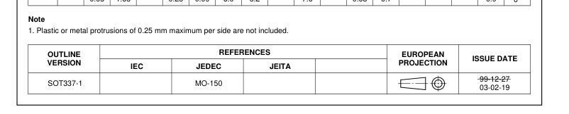
SSOP14: plastic shrink small outline package; 14 leads; body width 5.3 mm
SOT337-1
| pin 1 i | ndex |

Page 19

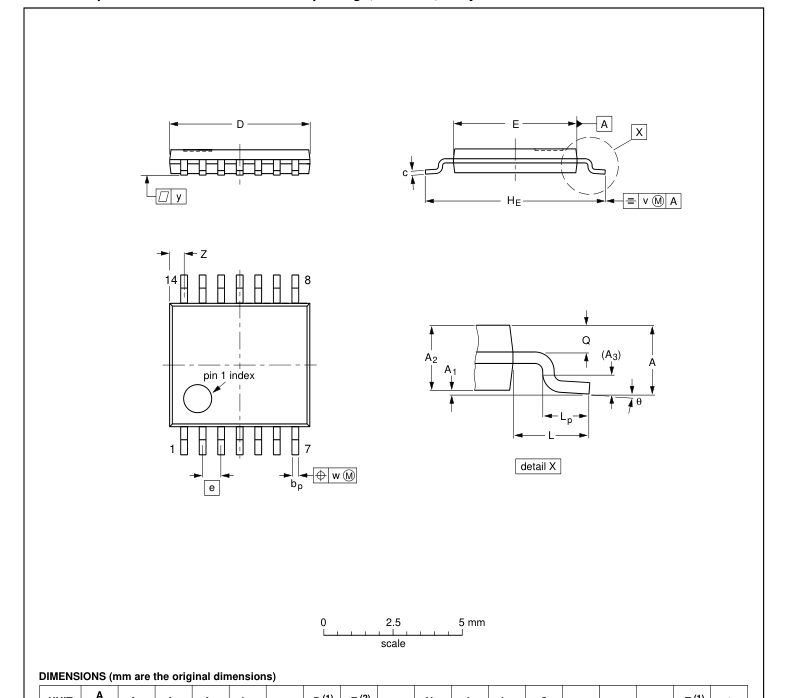
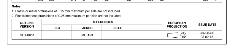
TSSOP14: plastic thin shrink small outline package; 14 leads; body width 4.4 mm
SOT402-1

Page 20
74HC74; 74HCT74
positive-edge trigger
DHVQFN14: plastic dual in-line compatible thermal enhanced very thin quad flat package; no leads;
SOT762-1
14 terminals; body 2.5 x 3 x 0.85 mm
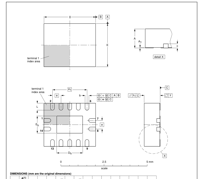

Note 1. Plastic or metal protrusions of 0.075 mm maximum per side are not included.
| OUTLINE VERSION | REFERENCES | EUROPEAN PROJECTION | ISSUE DATE | ||||
| IEC | JEDEC | JEITA | |||||
| SOT762-1 | - - - | MO-241 | - - - | 02-10-17 03-01-27 | |||
Page 21

DATA SHEET STATUS
| LEVEL | DATA SHEET STATUS(1) | PRODUCT STATUS(2)(3) | DEFINITION |
| I | Objective data | Development | This data sheet contains data from the objective specification for product development. Philips Semiconductors reserves the right to change the specification in any manner without notice. |
| II | Preliminary data | Qualification | This data sheet contains data from the preliminary specification. Supplementary data will be published at a later date. Philips Semiconductors reserves the right to change the specification without notice, in order to improve the design and supply the best possible product. |
| III | Product data | Production | This data sheet contains data from the product specification. Philips Semiconductors reserves the right to make changes at any time in order to improve the design, manufacturing and supply. Relevant changes will be communicated via a Customer Product/Process Change Notification (CPCN). |
Notes 1. Please consult the most recently issued data sheet before initiating or completing a design. 2. The product status of the device(s) described in this data sheet may have changed since this data sheet was published. The latest information is available on the Internet at URL http://www.semiconductors.philips.com. 3. For data sheets describing multiple type numbers, the highest-level product status determines the data sheet status.
DEFINITIONS
Short-form specification The data in a short-form specification is extracted from a full data sheet with the same type number and title. For detailed information see the relevant data sheet or data handbook. Limiting values definition Limiting values given are in accordance with the Absolute Maximum Rating System (IEC 60134). Stress above one or more of the limiting values may cause permanent damage to the device. These are stress ratings only and operation of the device at these or at any other conditions above those given in the Characteristics sections of the specification is not implied. Exposure to limiting values for extended periods may affect device reliability.
Application information Applications that are described herein for any of these products are for illustrative purposes only. Philips Semiconductors make no representation or warranty that such applications will be suitable for the specified use without further testing or modification.
DISCLAIMERS
Life support applications These products are not designed for use in life support appliances, devices, or systems where malfunction of these products can reasonably be expected to result in personal injury. Philips Semiconductors customers using or selling these products for use in such applications do so at their own risk and agree to fully indemnify Philips Semiconductors for any damages resulting from such application. Right to make changes Philips Semiconductors reserves the right to make changes in the products - including circuits, standard cells, and/or software - described or contained herein in order to improve design and/or performance. When the product is in full production
(status ‘Production’), relevant changes will be communicated via a Customer Product/Process Change Notification (CPCN). Philips Semiconductors assumes no responsibility or liability for the use of any of these products, conveys no licence or title under any patent, copyright, or mask work right to these products, and makes no representations or warranties that these products are free from patent, copyright, or mask work right infringement, unless otherwise specified.
Page 22
Philips Semiconductors – a worldwide company
Contact information
For additional information please visit http://www.semiconductors.philips.com.
Fax: +31 40 27 24825
For sales offices addresses send e-mail to: sales.addresses@www.semiconductors.philips.com.
SCA75
© Koninklijke Philips Electronics N.V. 2003
All rights are reserved. Reproduction in whole or in part is prohibited without the prior written consent of the copyright owner. The information presented in this document does not form part of any quotation or contract, is believed to be accurate and reliable and may be changed without notice. No liability will be accepted by the publisher for any consequence of its use. Publication thereof does not convey nor imply any license under patent- or other industrial or intellectual property rights.
Printed in The Netherlands
613508/03/pp22
Date of release: 2003 Jul 10
Document order number: 9397 750 11259