Download PDF
74HCT7273 PHILIPS
Document overview
- PDF pages: 20
Technical content
Page 1
INTEGRATED CIRCUITS


Page 2

FEATURES
DESCRIPTION
The 74HCT7273 is a high-speed SI-gate CMOS device and is pin compatible
- ESD protection:
with Low power Schottky TTL (LSTTL). It is specified in compliance with
HBM EIA/JESD22-A114-A Exceeds 2000 V
JEDEC standard no 7A.
MM EIA/JESD22-A115-A
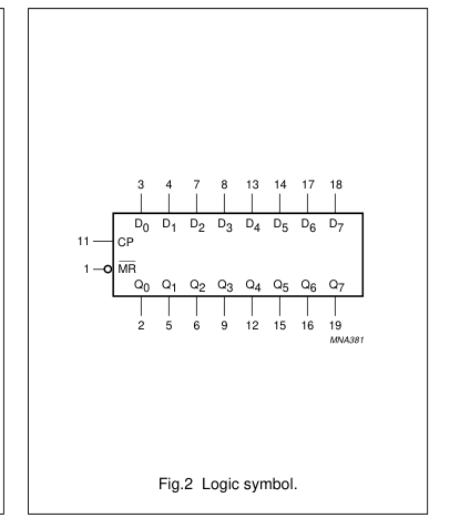
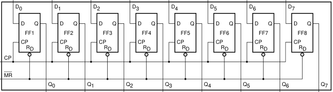
The 74HCT7273 has eight edge-triggered D-type flip-flops with individual D
Exceeds 200 V
inputs and Q outputs. The common Clock (CP) and Master Reset (MR) inputs
- Ideal buffer for MOS
load and reset (clear) all flip-flops simultaneously.
microprocessor or memory
The state of each D input, one set-up time before the LOW-to-HIGH clock
- Eight positive edge-triggered
transition, is transferred to the corresponding output (Qn) of the flip-flop.
D-type flip-flops
A LOW level on the MR input forces all outputs LOW, independently of the clock
- Common clock and master reset
or data inputs.
- Output capability: standard (open
The device is useful for applications requiring true outputs only and clock and
drain)
master reset inputs that are common to all storage elements.
- ICC category: MSI.
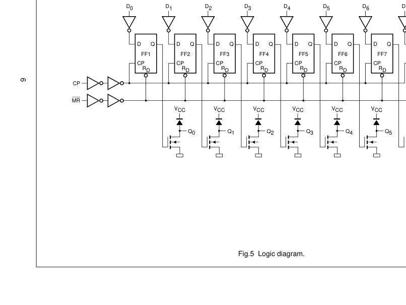
The 74HCT7273 has open-drain N-outputs, which are clamped by a diode connected to VCC. When a HIGH is clocked in the flip-flop, the output comes in the high-impedance OFF-state. The output may now be pulled to any voltage between GND and VOmax. This allows the device to be used as a LOW-to-HIGH or HIGH-to-LOW level shifter. For digital operation and OR-tied output applications, the device must have a pull-up resistor to establish a logic HIGH level.
QUICK REFERENCE DATA
Ground = 0 V; Tamb = 25 °C; tr = tf = 6.0 ns.
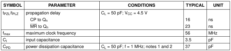
Notes 1. CPD is used to determine the dynamic power dissipation (PD in µW). PD = CPD × VCC2 × fi + ∑ (CL × VCC2 × fo) + ∑(V02/RL) × duty factor LOW where: fi = input frequency in MHz; fo = output frequency in MHz; ∑ (CL × VCC2 × fo) = sum of outputs; CL = output load capacitance in pF; RL = pull-up resistor in MΩ; VCC = supply voltage in Volts. 2. The condition is VI = GND to VCC − 1.5 V.
Page 3

FUNCTION TABLE
See note 1.
| OPERATING MODES | INPUTS | OUTPUTS | ||
| MR | CP | D n | Q n | |
| Reset (clear) | L | X | X | L |
| Load ‘1’ | H | ↑ | h | Z |
| Load ‘0’ | H | ↑ | l | L |
Note 1. H = HIGH voltage level; h = HIGH voltage level one set-up time prior to the LOW-to-HIGH CP transition; L = LOW voltage level. l = LOW voltage level one set-up time prior to the LOW-to-HIGH CP transition; Z = high-impedance OFF-state; X = don’t care; ↑ = LOW-to-HIGH CP transition.
ORDERING INFORMATION
| OUTSIDENORTH AMERICA | NORTH AMERICA | PACKAGE | ||||
| TEMPERATURE RANGE | PINS | PACKAGE | MATERIAL | CODE | ||
| 74HCT7273D | 74HCT7273D | −40 to +125 °C | 20 | SO | plastic | SOT163-1 |
| 74HCT7273N | 74HCT7273N | 20 | DIP | plastic | SOT146-1 | |
Page 4

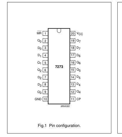
PINNING
| PIN | SYMBOL | DESCRIPTION |
|---|---|---|
| 1 | MR | asynchronous master reset (active LOW) |
| 2, 5, 6, 9, 12, 15, 16, 19 | Q to Q 0 7 | flip-flop outputs |
| 3, 4, 7, 8, 13, 14, 17, 18 | D to D 0 7 | data inputs |
| 10 | GND | ground (0 V) |
| 11 | CP | clock input (LOW-to-HIGH, edge triggered) |
| 20 | V CC | DC supply voltage |
Page 5

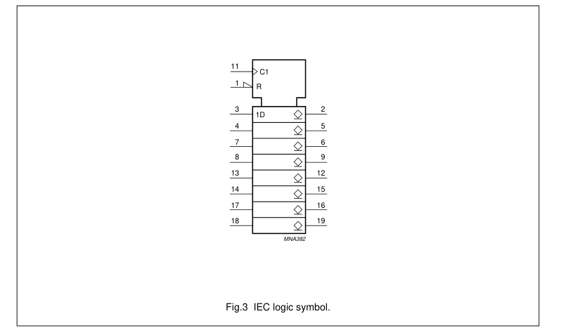

11
1
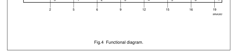
Page 6

Page 7

RECOMMENDED OPERATING CONDITIONS
| SYMBOL | PARAMETER | CONDITIONS | TYPE | UNIT | ||
|---|---|---|---|---|---|---|
| MIN. | TYP. | MAX. | ||||
| V CC | DC supply voltage | 4.5 | 5.0 | 5.5 | V | |
| V I | input voltage | 0 | − | V CC | V | |
| V O | output voltage | 0 | − | V CC | V | |
| T amb | operating ambient temperature | see DC and AC characteristics per device | −40 | − | +85 | °C |
| −40 | − | +125 | °C | |||
| t,t (∆t/∆f) r f | input rise and fall times except for Schmitt-trigger inputs | V = 2.0 V CC | − | 6.0 | 500 | ns/V |
| V = 4.5 V CC | − | 6.0 | 500 | |||
| V = 6.0 V CC | − | 6.0 | 500 | |||
LIMITING VALUES
In accordance with the Absolute Maximum Rating System (IEC 134); voltages are referenced to GND (ground = 0 V).
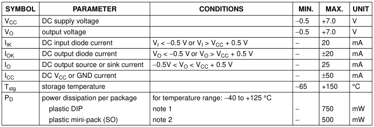
Note 1. For DIP package: above 70 °C the value of PD derates linearly with 12 mW/K. 2. For SO package: above 70 °C the value of PD derates linearly with 8 mW/K.
Page 8

DC CHARACTERISTICS
Over recommended operating conditions; voltages are referenced to GND (ground = 0 V).
| SYMBOL | PARAMETER | TEST CONDITIONS | T (°C) amb | UNIT | |||||||
|---|---|---|---|---|---|---|---|---|---|---|---|
| OTHER | V (V) CC | 25 | −40 to +85 | −40 to +125 | |||||||
| MIN. | TYP. | MAX. | MIN. | MAX. | MIN. | MAX. | |||||
| V IH | HIGH-level input voltage | 4.5 to 5.5 | 2.0 | 1.6 | − | 2.0 | − | 2.0 | − | V | |
| V IL | LOW-level input voltage | 4.5 to 5.5 | − | 1.2 | 0.8 | − | 0.8 | − | 0.8 | V | |
| V OL | LOW-level output voltage | V = V or V IL; I IH I = 20 µA O | 4.5 | − | 0 | 0.1 | − | 0.1 | − | 0.1 | V |
| V = V or V IL; I IH I = 4.0 mA O | 4.5 | − | 0.15 | 0.26 | − | 0.33 | − | 0.4 | V | ||
| I I | input leakage current | V = V or V I IH IL | 5.5 | − | − | 0.1 | − | 1.0 | − | 1.0 | µA |
| I OZ | HIGH level output leakage current | V = V IL; I V = V or GND O CC | 4.5 to 5.5 | − | − | ±0.5 | − | ±5.0 | − | ±10.0 | µA |
| I CC | quiescent supply current | V = V or GND; I CC I = 0 O | 5.5 | − | − | 8.0 | − | 80 | − | 160 | µA |
| ∆I CC | additional quiescent supply current per input pin | V = V −2.1 V I CC other inputs at V or GND; CC I = 0; note 1 O | 4.5 to 5.5 | − | 100 | 360 | − | 450 | − | 490 | µA |
Note 1. The value off additional quiescent supply current (∆ICC) for a unit load of 1 is given in the specifications. To determine ∆ICC per input, multiply this value by the unit load coefficient shown in Table 1.
Table 1
| INPUT | UNIT LOAD COEFFICIENT |
|---|---|
| MR | 1.50 |
| CP | 1.50 |
| D n | 0.40 |
Page 9

AC CHARACTERISTICS
Ground = 0 V; tr = tf ≤ 6.0 ns; CL = 50 pF.
| SYMBOL | PARAMETER | TEST CONDITIONS | T (°C) amb | UNIT | |||||||
|---|---|---|---|---|---|---|---|---|---|---|---|
| WAVEFORMS | V (V) CC | 25 | −40 to +85 | −40 to +125 | |||||||
| MIN. | TYP. | MAX. | MIN. | MAX. | MIN. | MAX. | |||||
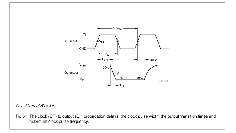
| t /t PZL PLZ | propagation delay CP to Q n | see Figs 6 and 9 | 4.5 | − | 16 | 30 | − | 38 | − | 45 | ns |
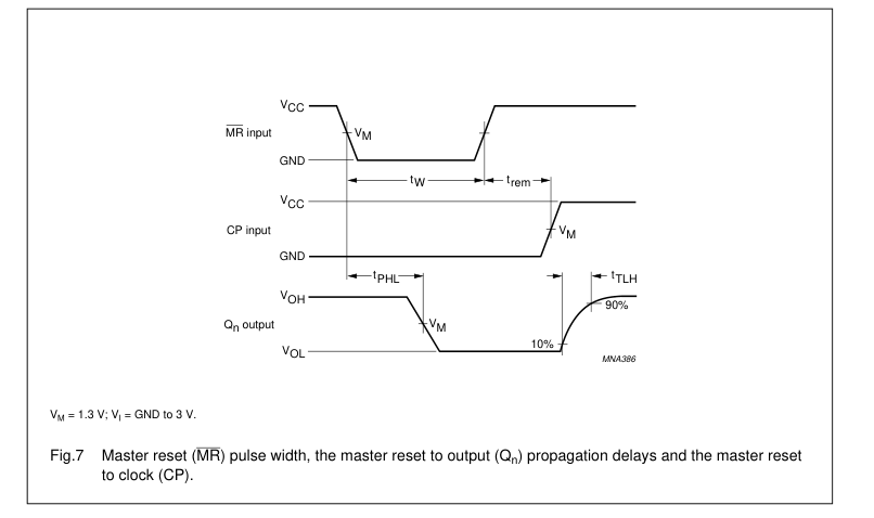
| t PZL | propagation delay MR to Q n | see Figs 6 and 9 | 4.5 | − | 23 | 34 | − | 43 | − | 51 | ns |
| t THL | output transition time | see Figs 6 and 9 | 4.5 | − | 7 | 15 | − | 19 | − | 22 | ns |
| t TLH | output transition time | see Figs 7 and 9 | 4.5 | − | − | 110 | − | 110 | − | 110 | ns |
| t W | clock pulse width HIGH or LOW | see Figs 6 and 9 | 4.5 | 16 | 9 | − | 20 | − | 24 | − | ns |
| t W | master reset pulse width; LOW | see Figs 7 and 9 | 4.5 | 16 | 8 | − | 20 | − | 24 | − | ns |
| t rem | removal time MR to CP | see Figs 7 and 9 | 4.5 | 10 | −2 | − | 13 | − | 15 | − | ns |
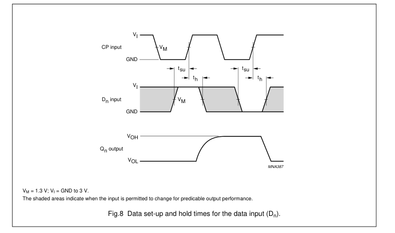
| t su | set-up time D to CP n | see Figs 8 and 9 | 4.5 | 12 | 5 | − | 15 | − | 18 | − | ns |
| t h | hold time D to CP n | see Figs 8 and 9 | 4.5 | 3 | −4 | − | 3 | − | 3 | − | ns |
| f max | maximum clock pulse frequency | see Figs 6 and 9 | 4.5 | 30 | 56 | − | 24 | − | 20 | − | MHz |
Page 10

AC WAVEFORMS
Page 11

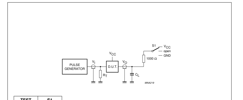

| TEST | S1 |
| t /t PLH PHL | open |
| t /t PLZ PZL | V CC |
| t /t PHZ PZH | GND |
Fig.9 Load circuit for switching times.
Page 12

PACKAGE OUTLINES
SO20: plastic small outline package; 20 leads; body width 7.5 mm
SOT163-1
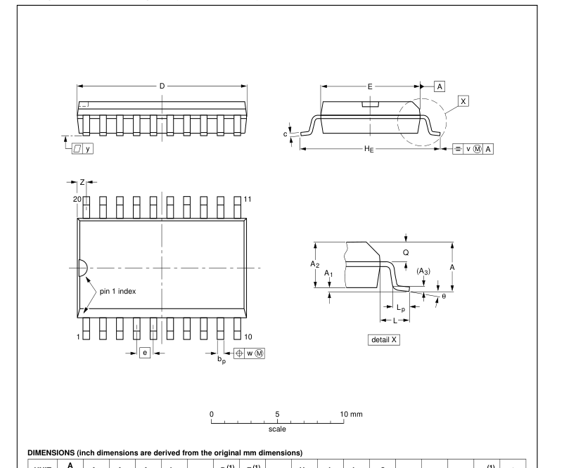

Note 1. Plastic or metal protrusions of 0.15 mm maximum per side are not included.
| OUTLINE VERSION | REFERENCES | EUROPEAN PROJECTION | ISSUE DATE | ||||
| IEC | JEDEC | EIAJ | |||||
| SOT163-1 | 075E04 | MS-013AC | 95-01-24 97-05-22 | ||||
Page 13

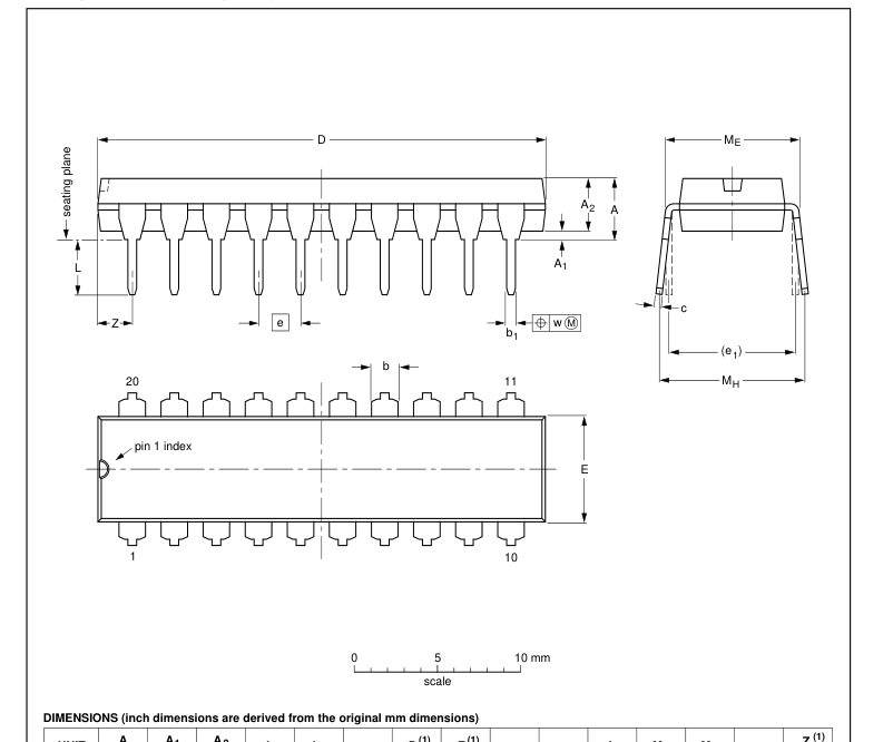
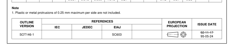
DIP20: plastic dual in-line package; 20 leads (300 mil)
SOT146-1

Page 14

SOLDERING
Introduction to soldering surface mount packages This text gives a very brief insight to a complex technology. A more in-depth account of soldering ICs can be found in our “Data Handbook IC26; Integrated Circuit Packages” (document order number 9398 652 90011). There is no soldering method that is ideal for all surface mount IC packages. Wave soldering is not always suitable for surface mount ICs, or for printed-circuit boards with high population densities. In these situations reflow soldering is often used.
Reflow soldering Reflow soldering requires solder paste (a suspension of fine solder particles, flux and binding agent) to be applied to the printed-circuit board by screen printing, stencilling or pressure-syringe dispensing before package placement. Several methods exist for reflowing; for example, infrared/convection heating in a conveyor type oven. Throughput times (preheating, soldering and cooling) vary between 100 and 200 seconds depending on heating method. Typical reflow peak temperatures range from 215 to 250 °C. The top-surface temperature of the packages should preferable be kept below 230 °C.
Wave soldering Conventional single wave soldering is not recommended for surface mount devices (SMDs) or printed-circuit boards with a high component density, as solder bridging and non-wetting can present major problems. To overcome these problems the double-wave soldering method was specifically developed.
If wave soldering is used the following conditions must be observed for optimal results:
- Use a double-wave soldering method comprising a turbulent wave with high upward pressure followed by a smooth laminar wave.
- For packages with leads on two sides and a pitch (e): – larger than or equal to 1.27 mm, the footprint longitudinal axis is preferred to be parallel to the transport direction of the printed-circuit board;
– smaller than 1.27 mm, the footprint longitudinal axis must be parallel to the transport direction of the printed-circuit board. The footprint must incorporate solder thieves at the downstream end.
- For packages with leads on four sides, the footprint must be placed at a 45° angle to the transport direction of the printed-circuit board. The footprint must incorporate solder thieves downstream and at the side corners.
During placement and before soldering, the package must be fixed with a droplet of adhesive. The adhesive can be applied by screen printing, pin transfer or syringe dispensing. The package can be soldered after the adhesive is cured. Typical dwell time is 4 seconds at 250 °C. A mildly-activated flux will eliminate the need for removal of corrosive residues in most applications.
Manual soldering Fix the component by first soldering two diagonally-opposite end leads. Use a low voltage (24 V or less) soldering iron applied to the flat part of the lead. Contact time must be limited to 10 seconds at up to 300 °C. When using a dedicated tool, all other leads can be soldered in one operation within 2 to 5 seconds between 270 and 320 °C.
Page 15

Suitability of surface mount IC packages for wave and reflow soldering methods
| PACKAGE | SOLDERING METHOD | |
| WAVE | REFLOW(1) | |
| BGA, SQFP HLQFP, HSQFP, HSOP, SMS PLCC(3), SO, SOJ LQFP, QFP, TQFP SSOP, TSSOP, VSO | not suitable not suitable(2) suitable not recommended(3)(4) not recommended(5) | suitable suitable suitable suitable suitable |
Notes 1. All surface mount (SMD) packages are moisture sensitive. Depending upon the moisture content, the maximum temperature (with respect to time) and body size of the package, there is a risk that internal or external package cracks may occur due to vaporization of the moisture in them (the so called popcorn effect). For details, refer to the Drypack information in the “Data Handbook IC26; Integrated Circuit Packages; Section: Packing Methods”. 2. These packages are not suitable for wave soldering as a solder joint between the printed-circuit board and heatsink (at bottom version) can not be achieved, and as solder may stick to the heatsink (on top version).
- If wave soldering is considered, then the package must be placed at a 45° angle to the solder wave direction. The package footprint must incorporate solder thieves downstream and at the side corners. 4. Wave soldering is only suitable for LQFP, TQFP and QFP packages with a pitch (e) equal to or larger than 0.8 mm; it is definitely not suitable for packages with a pitch (e) equal to or smaller than 0.65 mm. 5. Wave soldering is only suitable for SSOP and TSSOP packages with a pitch (e) equal to or larger than 0.65 mm; it is definitely not suitable for packages with a pitch (e) equal to or smaller than 0.5 mm.
Introduction to soldering through-hole mount packages This text gives a brief insight to wave, dip and manual soldering. A more in-depth account of soldering ICs can be found in our “Data Handbook IC26; Integrated Circuit Packages” (document order number 9398 652 90011). Wave soldering is the preferred method for mounting of through-hole mount IC packages on a printed-circuit board.
Soldering by dipping or by solder wave The maximum permissible temperature of the solder is 260 °C; solder at this temperature must not be in contact with the joints for more than 5 seconds. The total contact time of successive solder waves must not exceed 5 seconds. The device may be mounted up to the seating plane, but the temperature of the plastic body must not exceed the specified maximum storage temperature (Tstg(max)). If the printed-circuit board has been pre-heated, forced cooling may be necessary immediately after soldering to keep the temperature within the permissible limit.
Manual soldering Apply the soldering iron (24 V or less) to the lead(s) of the package, either below the seating plane or not more than 2 mm above it. If the temperature of the soldering iron bit is less than 300 °C it may remain in contact for up to 10 seconds. If the bit temperature is between 300 and 400 °C, contact may be up to 5 seconds.
Page 16

Suitability of through-hole mount IC packages for dipping and wave soldering methods
| PACKAGE | SOLDERING METHOD | |
| DIPPING | WAVE | |
| DBS, DIP, HDIP, SDIP, SIL | suitable | suitable(1) |
Note 1. For SDIP packages, the longitudinal axis must be parallel to the transport direction of the printed-circuit board.
DEFINITIONS
| Data sheet status | |
| Objective specification | This data sheet contains target or goal specifications for product development. |
| Preliminary specification | This data sheet contains preliminary data; supplementary data may be published later. |
| Product specification | This data sheet contains final product specifications. |
| Limiting values | |
| Limiting values given are in accordance with the Absolute Maximum Rating System (IEC 134). Stress above one or more of the limiting values may cause permanent damage to the device. These are stress ratings only and operation of the device at these or at any other conditions above those given in the Characteristics sections of the specification is not implied. Exposure to limiting values for extended periods may affect device reliability. | |
| Application information | |
| Where application information is given, it is advisory and does not form part of the specification. | |
LIFE SUPPORT APPLICATIONS
These products are not designed for use in life support appliances, devices, or systems where malfunction of these products can reasonably be expected to result in personal injury. Philips customers using or selling these products for use in such applications do so at their own risk and agree to fully indemnify Philips for any damages resulting from such improper use or sale.
Page 17

NOTES
Page 18

NOTES
Page 19

NOTES
Page 20
Philips Semiconductors – a worldwide company
Argentina: see South America Australia: 3 Figtree Drive, HOMEBUSH, NSW 2140, Tel. +61 2 9704 8141, Fax. +61 2 9704 8139 Austria: Computerstr. 6, A-1101 WIEN, P.O. Box 213, Tel. +43 1 60 101 1248, Fax. +43 1 60 101 1210 Belarus: Hotel Minsk Business Center, Bld. 3, r. 1211, Volodarski Str. 6, 220050 MINSK, Tel. +375 172 20 0733, Fax. +375 172 20 0773 Belgium: see The Netherlands Brazil: see South America Bulgaria: Philips Bulgaria Ltd., Energoproject, 15th floor, 51 James Bourchier Blvd., 1407 SOFIA, Tel. +359 2 68 9211, Fax. +359 2 68 9102 Canada: PHILIPS SEMICONDUCTORS/COMPONENTS, Tel. +1 800 234 7381, Fax. +1 800 943 0087 China/Hong Kong: 501 Hong Kong Industrial Technology Centre,
72 Tat Chee Avenue, Kowloon Tong, HONG KONG, Tel. +852 2319 7888, Fax. +852 2319 7700 Colombia: see South America Czech Republic: see Austria Denmark: Sydhavnsgade 23, 1780 COPENHAGEN V, Tel. +45 33 29 3333, Fax. +45 33 29 3905 Finland: Sinikalliontie 3, FIN-02630 ESPOO, Tel. +358 9 615 800, Fax. +358 9 6158 0920 France: 51 Rue Carnot, BP317, 92156 SURESNES Cedex, Tel. +33 1 4099 6161, Fax. +33 1 4099 6427 Germany: Hammerbrookstraße 69, D-20097 HAMBURG, Tel. +49 40 2353 60, Fax. +49 40 2353 6300 Hungary: see Austria India: Philips INDIA Ltd, Band Box Building, 2nd floor, 254-D, Dr. Annie Besant Road, Worli, MUMBAI 400 025, Tel. +91 22 493 8541, Fax. +91 22 493 0966
Indonesia: PT Philips Development Corporation, Semiconductors Division, Gedung Philips, Jl. Buncit Raya Kav.99-100, JAKARTA 12510, Tel. +62 21 794 0040 ext. 2501, Fax. +62 21 794 0080 Ireland: Newstead, Clonskeagh, DUBLIN 14, Tel. +353 1 7640 000, Fax. +353 1 7640 200 Israel: RAPAC Electronics, 7 Kehilat Saloniki St, PO Box 18053, TEL AVIV 61180, Tel. +972 3 645 0444, Fax. +972 3 649 1007 Italy: PHILIPS SEMICONDUCTORS, Via Casati, 23 - 20052 MONZA (MI), Tel. +39 039 203 6838, Fax +39 039 203 6800 Japan: Philips Bldg 13-37, Kohnan 2-chome, Minato-ku, TOKYO 108-8507, Tel. +81 3 3740 5130, Fax. +81 3 3740 5057 Korea: Philips House, 260-199 Itaewon-dong, Yongsan-ku, SEOUL,
Tel. +82 2 709 1412, Fax. +82 2 709 1415 Malaysia: No. 76 Jalan Universiti, 46200 PETALING JAYA, SELANGOR, Tel. +60 3 750 5214, Fax. +60 3 757 4880 Mexico: 5900 Gateway East, Suite 200, EL PASO, TEXAS 79905, Tel. +9-5 800 234 7381, Fax +9-5 800 943 0087 Middle East: see Italy
For all other countries apply to: Philips Semiconductors, International Marketing & Sales Communications, Building BE-p, P.O. Box 218, 5600 MD EINDHOVEN, The Netherlands, Fax. +31 40 27 24825
© Philips Electronics N.V. 1999
Netherlands: Postbus 90050, 5600 PB EINDHOVEN, Bldg. VB, Tel. +31 40 27 82785, Fax. +31 40 27 88399 New Zealand: 2 Wagener Place, C.P.O. Box 1041, AUCKLAND, Tel. +64 9 849 4160, Fax. +64 9 849 7811 Norway: Box 1, Manglerud 0612, OSLO, Tel. +47 22 74 8000, Fax. +47 22 74 8341 Pakistan: see Singapore Philippines: Philips Semiconductors Philippines Inc., 106 Valero St. Salcedo Village, P.O. Box 2108 MCC, MAKATI, Metro MANILA, Tel. +63 2 816 6380, Fax. +63 2 817 3474 Poland: Al.Jerozolimskie 195 B, 02-222 WARSAW, Tel. +48 22 5710 000, Fax. +48 22 5710 001 Portugal: see Spain Romania: see Italy Russia: Philips Russia, Ul. Usatcheva 35A, 119048 MOSCOW, Tel. +7 095 755 6918, Fax. +7 095 755 6919
Singapore: Lorong 1, Toa Payoh, SINGAPORE 319762, Tel. +65 350 2538, Fax. +65 251 6500 Slovakia: see Austria Slovenia: see Italy South Africa: S.A. PHILIPS Pty Ltd., 195-215 Main Road Martindale, 2092 JOHANNESBURG, P.O. Box 58088 Newville 2114, Tel. +27 11 471 5401, Fax. +27 11 471 5398 South America: Al. Vicente Pinzon, 173, 6th floor, 04547-130 SÃO PAULO, SP, Brazil, Tel. +55 11 821 2333, Fax. +55 11 821 2382 Spain: Balmes 22, 08007 BARCELONA, Tel. +34 93 301 6312, Fax. +34 93 301 4107 Sweden: Kottbygatan 7, Akalla, S-16485 STOCKHOLM, Tel. +46 8 5985 2000, Fax. +46 8 5985 2745 Switzerland: Allmendstrasse 140, CH-8027 ZÜRICH, Tel. +41 1 488 2741 Fax. +41 1 488 3263
Taiwan: Philips Semiconductors, 6F, No. 96, Chien Kuo N. Rd., Sec. 1, TAIPEI, Taiwan Tel. +886 2 2134 2886, Fax. +886 2 2134 2874 Thailand: PHILIPS ELECTRONICS (THAILAND) Ltd., 209/2 Sanpavuth-Bangna Road Prakanong, BANGKOK 10260, Tel. +66 2 745 4090, Fax. +66 2 398 0793 Turkey: Yukari Dudullu, Org. San. Blg., 2.Cad. Nr. 28 81260 Umraniye, ISTANBUL, Tel. +90 216 522 1500, Fax. +90 216 522 1813 Ukraine: PHILIPS UKRAINE, 4 Patrice Lumumba str., Building B, Floor 7, 252042 KIEV, Tel. +380 44 264 2776, Fax. +380 44 268 0461 United Kingdom: Philips Semiconductors Ltd., 276 Bath Road, Hayes, MIDDLESEX UB3 5BX, Tel. +44 208 730 5000, Fax. +44 208 754 8421 United States: 811 East Arques Avenue, SUNNYVALE, CA 94088-3409,
Tel. +1 800 234 7381, Fax. +1 800 943 0087 Uruguay: see South America Vietnam: see Singapore Yugoslavia: PHILIPS, Trg N. Pasica 5/v, 11000 BEOGRAD, Tel. +381 11 62 5344, Fax.+381 11 63 5777
Internet: http://www.semiconductors.philips.com
SCA68
All rights are reserved. Reproduction in whole or in part is prohibited without the prior written consent of the copyright owner. The information presented in this document does not form part of any quotation or contract, is believed to be accurate and reliable and may be changed without notice. No liability will be accepted by the publisher for any consequence of its use. Publication thereof does not convey nor imply any license under patent- or other industrial or intellectual property rights.
Printed in The Netherlands
245002/01/pp20
Date of release: 1999 Oct 01
Document order number: 9397 750 05733