Download PDF
74HC670 PHILIPS
Document overview
- PDF pages: 9
Technical content
Page 1
Page 2
FEATURES
- Simultaneous and independent read and write operations
- Expandable to almost any word size and bit length
- Output capability: bus driver
- ICC category: MSI
GENERAL DESCRIPTION
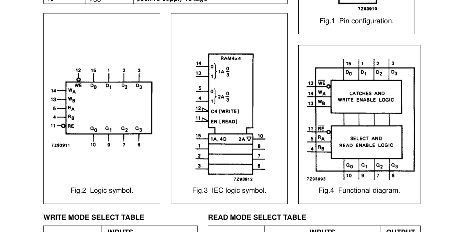
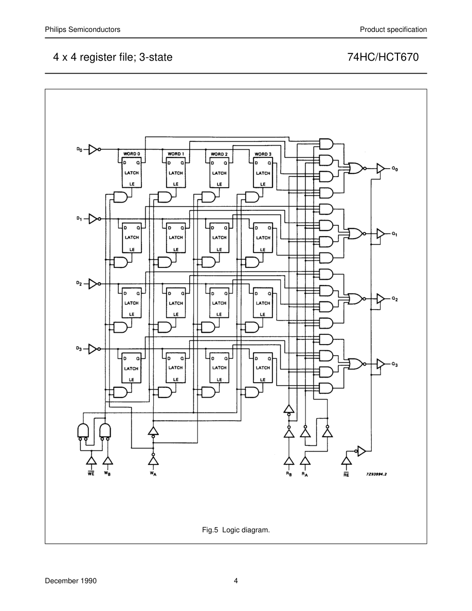
The 74HC/HCT670 are high-speed Si-gate CMOS devices and are pin compatible with low power Schottky TTL (LSTTL). They are specified in compliance with JEDEC standard no. 7A. The 74HC/HCT670 are 16-bit 3-state register files organized as 4 words of 4 bits each. Separated read and write address inputs (RA, RB and WA, WB) and enable inputs (RE and WE) are available, permitting simultaneous writing into one word location and reading from another location. The 4-bit word to be stored is presented to four data inputs (D0 to D3). The WA and WB inputs determine
QUICK REFERENCE DATA
GND = 0 V; Tamb = 25 °C; tr = tf = 6 ns
the location of the stored word. When the WE input is LOW, the data is entered into the addressed location. The addressed location remains transparent to the data while the WE input is LOW. Data supplied at the inputs will be read out in true (non-inverting) form from the 3-state outputs (Q0 to Q3). Dn and Wn inputs are inhibited when WE is HIGH. Direct acquisition of data stored in any of the four registers is made possible by individual read address inputs (RA and RB). The addressed word appears at the four outputs when the RE is LOW. Data outputs are in the high impedance OFF-state when RE is HIGH. This permits outputs to be tied together to increase the word capacity to
very large numbers. Design of the read enable signals for the stacked devices must ensure that there is no overlap in the LOW levels which would cause more than one output to be active at the same time. Parallel expansion to generate n-bit words is accomplished by driving the enable and address inputs of each device in parallel.
| SYMBOL | PARAMETER | CONDITIONS | TYPICAL | UNIT | |
|---|---|---|---|---|---|
| HC | HCT | ||||
| t / t PHL PLH | propagation delay D to Q n n | C = 15 pF; V = 5 V L CC | 23 | 23 | ns |
| C I | input capacitance | 3.5 | 3.5 | pF | |
| C PD | power dissipation capacitance per package | notes 1 and 2 | 122 | 124 | pF |
Notes 1. CPD is used to determine the dynamic power dissipation (PD in µW):
PD = CPD × VCC2 × fi + ∑ (CL × VCC2 × fo)
where:
fi = input frequency in MHz fo = output frequency in MHz ∑ (CL × VCC2 × fo) = sum of outputs CL = output load capacitance in pF VCC = supply voltage in V 2. For HC the condition is VI = GND to VCC; for HCT the condition is VI = GND to VCC −1.5 V
ORDERING INFORMATION
See “74HC/HCT/HCU/HCMOS Logic Package Information”.
Page 3
| PIN NO. | SYMBOL | NAME AND FUNCTION |
|---|---|---|
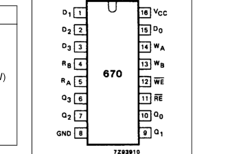
| 5, 4 8 10, 9, 7, 6 11 12 14, 13 15, 1, 2, 3 16 | R , R A B GND Q to Q 0 3 RE WE W , W A B D to D 0 3 V CC | read address inputs ground (0 V) data outputs 3-state output read enable input (active LOW) write enable input (active LOW) write address inputs data inputs positive supply voltage |
| OPERATING MODE | INPUTS | OUTPUT | |
| RE | INTERNAL LATCHES(1) | Q n | |
| read | L L | L H | L H |
| disabled | H | X | Z |
| OPERATING MODE | INPUTS | INTERNAL LATCHES(1) | |
| WE | D n | ||
| write data | L L | L H | L H |
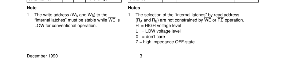
| data latched | H | X | no change |
Page 4
Page 5
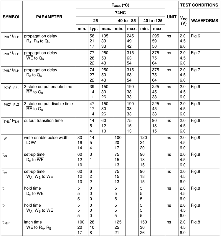

Page 6
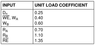
Page 7
| SYMBOL | PARAMETER | T (°C) amb | UNIT | TEST CONDITIONS | |||||||
|---|---|---|---|---|---|---|---|---|---|---|---|
| 74HCT | V CC (V) | WAVEFORMS | |||||||||
| +25 | −40 to +85 | −40 to +125 | |||||||||
| min. | typ. | max. | min. | max. | min. | max. | |||||
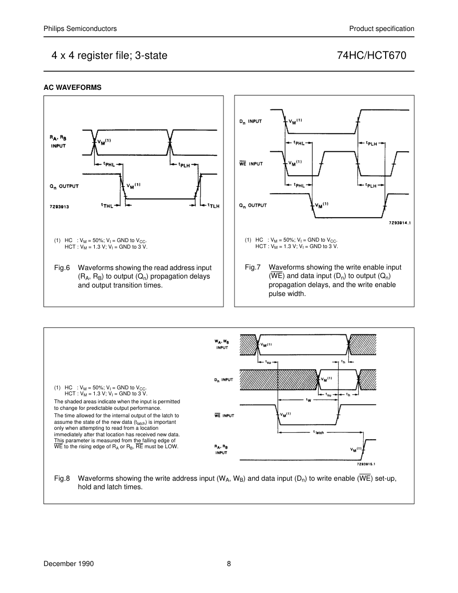
| t / t PHL PLH | propagation delay R , R to Q A B n | 21 | 40 | 50 | 60 | ns | 4.5 | Fig.6 | |||
| t / t PHL PLH | propagation delay WE to Q n | 28 | 50 | 63 | 75 | ns | 4.5 | Fig.7 | |||
| t / t PHL PLH | propagation delay D to Q n n | 27 | 50 | 63 | 75 | ns | 4.5 | Fig.7 | |||
| t / t PZH PZL | 3-state output enable time RE to Q n | 18 | 35 | 44 | 53 | ns | 4.5 | Fig.9 | |||
| t / t PHZ PLZ | 3-state output disable time RE to Q n | 19 | 35 | 44 | 53 | ns | 4.5 | Fig.9 | |||
| t / t THL TLH | output transition time | 5 | 12 | 15 | 18 | ns | 4.5 | Fig.6 | |||
| t W | write enable pulse width LOW | 18 | 9 | 23 | 27 | ns | 4.5 | Fig.8 | |||
| t su | set-up time D to WE n | 12 | 4 | 15 | 18 | ns | 4.5 | Fig.8 | |||
| t su | set-up time W , W to WE A B | 12 | −2 | 15 | 18 | ns | 4.5 | Fig.8 | |||
| t h | hold time D to WE n | 5 | −1 | 5 | 5 | ns | 4.5 | Fig.8 | |||
| t h | hold time W , W to WE A B | 5 | 0 | 5 | 5 | ns | 4.5 | Fig.8 | |||
| t latch | latch time WE to R , R A B | 25 | 11 | 31 | 38 | ns | 4.5 | Fig.8 | |||
Page 8
Page 9