Download PDF
74HC648 PHILIPS
Document overview
- PDF pages: 12
Technical content
Page 1
Page 2
FEATURES
- Independent register for A and B buses
- Multiplexed real-time and stored data
- Output capability: bus driver
- ICC category: MSI
GENERAL DESCRIPTION
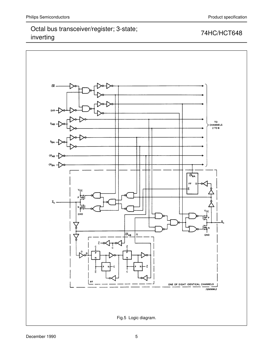
The 74HC/HCT648 are high-speed Si-gate CMOS devices and are pin compatible with low power Schottky TTL (LSTTL). They are specified in compliance with JEDEC standard no. 7A. The 74HC/HCT648 consist of bus transceiver circuits with 3-state inverting outputs, D-type flip-flops, and control circuitry arranged for multiplexed transmission of data directly from the internal registers. Data on the “A” or “B”
QUICK REFERENCE DATA
GND = 0 V; Tamb = 25 °C; tr = tf = 6 ns
bus will be clocked into the registers as the appropriate clock (CPAB and CPBA) goes to a HIGH logic level. Output enable (OE) and direction (DIR) inputs are provided to control the transceiver function. In the transceiver mode, data present at the high-impedance port may be stored in either the “A” or “B” register, or in both. The select source inputs (SAB and SBA) can multiplex stored and real-time (transparent mode) data. The direction (DIR) input determines which bus will receive data when OE is active (LOW). In the isolation mode (OE = HIGH), “A” data may be stored in the “B” register and/or “B” data may be stored in the “A” register. When an output function is disabled, the input function is
still enabled and may be used to store and transmit data. Only one of the two buses, A or B, may be driven at a time. The “648” is functionally identical to the “646”, but has inverting data paths.
| SYMBOL | PARAMETER | CONDITIONS | TYPICAL | UNIT | |
|---|---|---|---|---|---|
| HC | HCT | ||||
| t t PHL/ PLH | propagation delay A , B to B , A n n n n | C = 15 pF; V = 5 V L CC | 11 | 11 | ns |
| f max | maximum clock frequency | 75 | 88 | MHz | |
| C I | input capacitance | 3.5 | 3.5 | pF | |
| C PD | power dissipation capacitance per channel | notes 1 and 2 | 30 | 31 | pF |
Notes 1. CPD is used to determine the dynamic power dissipation (PD in µW): PD = CPD × VCC2 × fi +∑ (CL × VCC2 × fo) where: fi = input frequency in MHz fo = output frequency in MHz ∑ (CL × VCC2 × fo) = sum of outputs CL = output load capacitance in pF VCC = supply voltage in V 2. For HC the condition is VI = GND to VCC For HCT the condition is VI = GND to VCC − 1.5 V
ORDERING INFORMATION
See “74HC/HCT/HCU/HCMOS Logic Package Information”.
Page 3
| PIN NO. | SYMBOL | NAME AND FUNCTION |
|---|---|---|
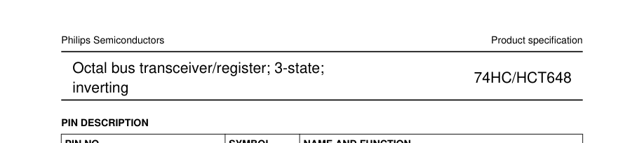
| 1 2 3 4, 5, 6, 7, 8, 9, 10, 11 12 20, 19, 18, 17, 16, 15, 14, 13 21 22 23 24 | CP AB S AB DIR A to A 0 7 GND B to B 0 7 OE S BA CP BA V CC | A to B clock input (LOW-to-HIGH, edge-triggered) select A to B source input direction control input A data inputs/outputs ground (0 V) B data inputs/outputs output enable input (active LOW) select B to A source input B to A clock input (LOW-to-HIGH, edge-triggered) positive supply voltage |
Page 4
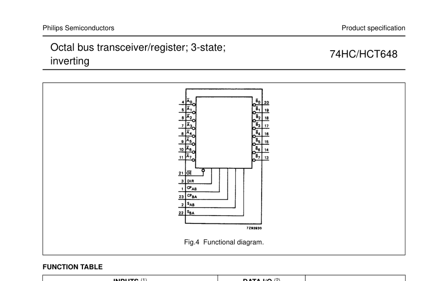
| INPUTS (1) | DATA I/O (2) | FUNCTION | ||||||
| OE | DIR | CP AB | CP BA | S AB | S BA | A TO A 0 7 | B TO B 0 7 | |
| H H | X X | H or L ↑ | H or L ↑ | X X | X X | input | input | isolation store A and B data |
| L L | L L | X X | X H or L | X X | L H | output | input | real-time B data to A bus stored B data to A bus |
| L L | H H | X H or L | X X | L H | X X | input | output | real-time A data to B bus stored A data to B bus |
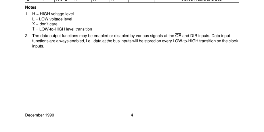
Page 5
Page 6

Page 7

Page 8
Page 9
Page 10
Page 11
Page 12