


 Download PDF
74HC594 NXP
Document overview
- PDF pages: 26
Technical content
Page 1
1. General description
The 74HC594; 74HCT594 is a high-speed Si-gate CMOS device and is pin compatible with Low-Power Schottky TTL (LSTTL).
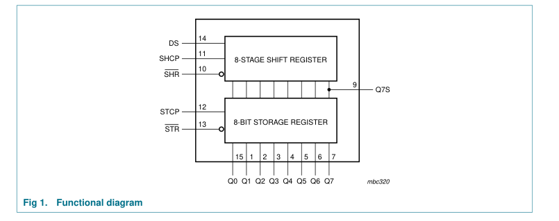
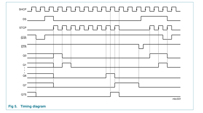
The 74HC594; 74HCT594 is an 8-bit, non-inverting, serial-in, parallel-out shift register that feeds an 8-bit D-type storage register. Separate clocks (SHCP and STCP) and direct overriding clears (SHR and STR) are provided on both the shift and storage registers. A serial output (Q7S) is provided for cascading purposes.
Both the shift and storage register clocks are positive-edge triggered. If the user wishes to connect both clocks together, the shift register will always be one count pulse ahead of the storage register.
2. Features
I Synchronous serial input and output I Complies with JEDEC standard No.7A I 8-bit parallel output I Shift and storage registers have independent direct clear and clocks I Independent clocks for shift and storage registers I 100 MHz (typical) I Multiple package options I Specified from −40 °C to +85 °C and from −40 °C to +125 °C
3. Applications
I Serial-to parallel data conversion I Remote control holding register

Page 2
4. Ordering information
Table 1. Ordering information
| Type number | Package | |||
|---|---|---|---|---|
| Temperature range | Name | Description | Version | |
plastic small outline package; 16 leads;
74HC594D
−40 °C to +125 °C SO16
SOT109-1
body width 3.9 mm plastic shrink small outline package; 16 leads;
74HC594DB
−40 °C to +125 °C SSOP16
SOT338-1
body width 5.3 mm plastic dual in-line package; 16 leads (300 mil)
74HC594N
−40 °C to +125 °C DIP16
SOT38-4
plastic small outline package; 16 leads;
74HCT594D
−40 °C to +125 °C SO16
SOT109-1
body width 3.9 mm plastic shrink small outline package; 16 leads;
74HCT594DB
−40 °C to +125 °C SSOP16
SOT338-1
body width 5.3 mm plastic dual in-line package; 16 leads (300 mil)
74HCT594N
−40 °C to +125 °C DIP16
SOT38-4
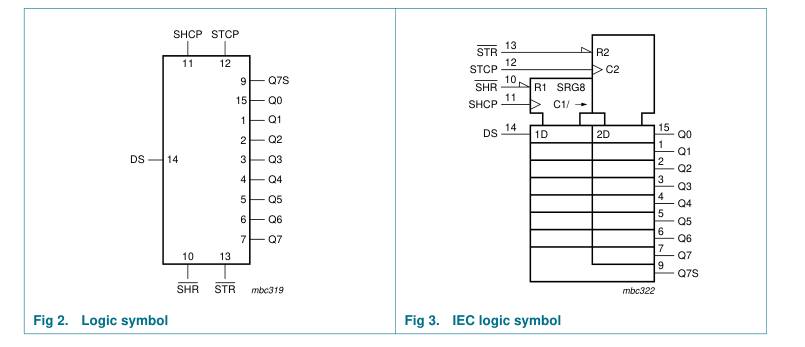
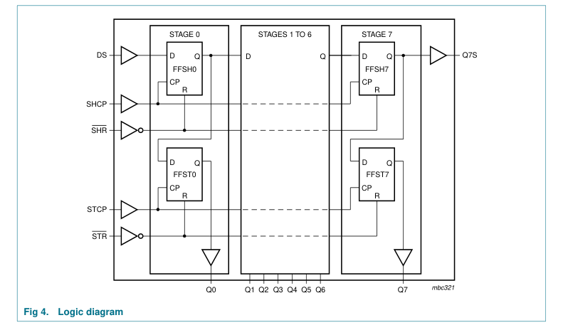
5. Functional diagram
2 of 26
Page 3
3 of 26
Page 4
6. Pinning information
6.1 Pinning
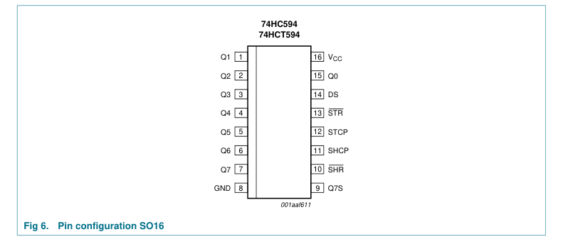
4 of 26
Page 5
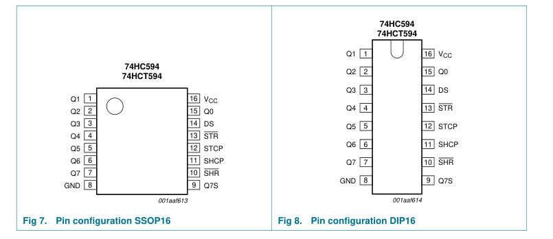
6.2 Pin description
Table 2. Pin description Symbol
Pin
Description
Q1
1
parallel data output 1
Q2
2
parallel data output 2
Q3
3
parallel data output 3
Q4
4
parallel data output 4
Q5
5
parallel data output 5
Q6
6
parallel data output 6
Q7
7
parallel data output 7
GND
8
ground (0 V)
Q7S
9
serial data output shift register reset (active LOW)
SHR
10
SHCP
11
shift register clock input storage register clock input
STCP
12
storage register reset (active LOW)
STR
13
DS
14
serial data input
Q0
15
parallel data output 0
16
supply voltage
VCC
5 of 26
Page 6
7. Functional description
Table 3. Function table[1]
| Function | Input | ||||
| SHR | STR | SHCP | STCP | DS | |
Clear shift register
L X X X X
Clear storage register
X L X X X
Load DS into shift register stage 0, advance previous stage data to the next stage H
X
X H or L
↑
Transfer shift register data to storage register and outputs Qn
X H X
X ↑
Shift register one count pulse ahead of storage register
H H
X
↑ ↑
[1] H = HIGH voltage level; L = LOW voltage level; ↑ = LOW-to-HIGH transition; X = don’t care.
8. Limiting values
Table 4. Limiting values In accordance with the Absolute Maximum Rating System (IEC 60134). Voltages are referenced to GND (ground = 0 V). Symbol
Parameter
Conditions
Min Max Unit
supply voltage
−0.5 +7.0 V
VCC
[1] -
input clamping current
VI < −0.5 V or VI > VCC + 0.5 V
±20 mA
IIK
[1] -
output clamping current
VO < −0.5 V or VO > VCC + 0.5 V
±20 mA
IOK
output current
VO = −0.5 V to VCC + 0.5 V
IO
Serial data output Q7S
- ±25 mA
Parallel data output
- ±35 mA
supply current
Serial data output Q7S
- 50 mA
ICC
Parallel data output
- 70 mA
ground current
Serial data output Q7S
- −50 mA
IGND
Parallel data output
- −70 mA
storage temperature
−65 +150 °C
Tstg
[2] -
total power dissipation
Tamb = −40 °C to +125 °C
500 mW
Ptot
[1] The input and output voltage ratings may be exceeded if the input and output current ratings are observed. [2] For DIP16 packages: above 70 °C the value of Ptot derates linearly with 12 mW/K. For SO16 packages: above 70 °C the value of Ptot derates linearly with 8 mW/K. For SSOP16 packages: above 60 °C the value of Ptot derates linearly with 5.5 mW/K.
6 of 26
Page 7
9. Recommended operating conditions
Table 5. Recommended operating conditions Symbol
Parameter
Conditions
Min Typ Max Unit
Type 74HC594
supply voltage
2.0 5.0 6.0 V
VCC
input voltage
0 - VCC V
VI
output voltage
0 - VCC V
VO
ambient temperature
−40 +25 +125 °C
Tamb
rise time
VCC = 2.0 V
- - 1000 ns
tr
VCC = 4.5 V
- 6.0 500 ns
VCC = 6.0 V
- - 400 ns
fall time
VCC = 2.0 V
- - 1000 ns
tf
VCC = 4.5 V
- 6.0 500 ns
VCC = 6.0 V
- - 400 ns
Type 74HCT594
supply voltage
4.5 5.0 5.5 V
VCC
input voltage
0 - VCC V
VI
output voltage
0 - VCC V
VO
ambient temperature
−40 +25 +125 °C
Tamb
rise time
VCC = 4.5 V
- 6.0 500 ns
tr
fall time
VCC = 4.5 V
- 6.0 500 ns
tf
10. Static characteristics
Table 6. Static characteristics type 74HC594 At recommended operating conditions; voltages are referenced to GND (ground = 0 V). Symbol Parameter
Conditions
Min Typ Max Unit
Tamb = 25 °C HIGH-level input voltage
VCC = 2.0 V
1.5 1.2 - V
VIH
VCC = 4.5 V
3.15 2.4 - V
VCC = 6.0 V
4.2 3.2 - V
LOW-level input voltage
VCC = 2.0 V
- 0.8 0.5 V
VIL
VCC = 4.5 V
- 2.1 1.35 V
VCC = 6.0 V
- 2.8 1.8 V
HIGH-level output voltage
VI = VIH or VIL
VOH
Serial data output Q7S IO = −4.0 mA; VCC = 4.5 V
3.98 4.32 - V
IO = −5.2 mA; VCC = 6.0 V
5.48 5.81 - V
Parallel data outputs IO = −6.0 mA; VCC = 4.5 V
3.98 4.32 - V
IO = −7.8 mA; VCC = 6.0 V
5.48 5.81 - V
7 of 26
Page 8
Table 6. Static characteristics type 74HC594 …continued At recommended operating conditions; voltages are referenced to GND (ground = 0 V). Symbol Parameter
Conditions
Min Typ Max Unit
VOL LOW-level output voltage
VI = VIH or VIL Serial data output Q7S IO = 4.0 mA; VCC = 4.5 V
- 0.15 0.26 V
IO = 5.2 mA; VCC = 6.0 V
- 0.16 0.26 V
Parallel data outputs IO = 6.0 mA; VCC = 4.5 V
- 0.15 0.26 V
IO = 7.8 mA; VCC = 6.0 V
- 0.16 0.26 V
input leakage current
VI = VCC or GND; VCC = 6.0 V
- - ±0.1 µA
II
supply current
VI = VCC or GND; IO = 0 A;
- - 8.0 µA
ICC
VCC = 6.0 V
input capacitance
- 3.5 - pF
Ci Tamb = −40 °C to +85 °C
HIGH-level input voltage
VCC = 2.0 V
1.5 - - V
VIH
VCC = 4.5 V
3.15 - - V
VCC = 6.0 V
4.2 - - V
LOW-level input voltage
VCC = 2.0 V
- - 0.5 V
VIL
VCC = 4.5 V
- - 1.35 V
VCC = 6.0 V
- - 1.8 V
HIGH-level output voltage
VI = VIH or VIL
VOH
Serial data output Q7S IO = −4.0 mA; VCC = 4.5 V
3.84 - - V
IO = −5.2 mA; VCC = 6.0 V
5.34 - - V
Parallel data outputs IO = −6.0 mA; VCC = 4.5 V
3.84 - - V
IO = −7.8 mA; VCC = 6.0 V
5.34 - - V
LOW-level output voltage
VI = VIH or VIL
VOL
Serial data output Q7S IO = 4.0 mA; VCC = 4.5 V
- - 0.33 V
IO = 5.2 mA; VCC = 6.0 V
- - 0.33 V
Parallel data outputs IO = 6.0 mA; VCC = 4.5 V
- - 0.33 V
IO = 7.8 mA; VCC = 6.0 V
- - 0.33 V
input leakage current
VI = VCC or GND; VCC = 6.0 V
- - ±1.0 µA
II
supply current
VI = VCC or GND; IO = 0 A;
- - 80 µA
ICC
VCC = 6.0 V
Tamb = −40 °C to +125 °C HIGH-level input voltage
VCC = 2.0 V
1.5 - - V
VIH
VCC = 4.5 V
3.15 - - V
VCC = 6.0 V
4.2 - - V
8 of 26
Page 9
Table 6. Static characteristics type 74HC594 …continued At recommended operating conditions; voltages are referenced to GND (ground = 0 V). Symbol Parameter
Conditions
Min Typ Max Unit
VIL LOW-level input voltage
VCC = 2.0 V
- - 0.5 V
VCC = 4.5 V
- - 1.35 V
VCC = 6.0 V
- - 1.8 V
HIGH-level output voltage
VI = VIH or VIL
VOH
Serial data output Q7S IO = −4.0 mA; VCC = 4.5 V
3.7 - - V
IO = −5.2 mA; VCC = 6.0 V
5.2 - - V
Parallel data outputs IO = −6.0 mA; VCC = 4.5 V
3.7 - - V
IO = −7.8 mA; VCC = 6.0 V
5.2 - - V
LOW-level output voltage
VI = VIH or VIL
VOL
Serial data output Q7S IO = 4.0 mA; VCC = 4.5 V
- - 0.4 V
IO = 5.2 mA; VCC = 6.0 V
- - 0.4 V
Parallel data outputs IO = 6.0 mA; VCC = 4.5 V
- - 0.4 V
IO = 7.8 mA; VCC = 6.0 V
- - 0.4 V
input leakage current
VI = VCC or GND; VCC = 6.0 V
- - ±1.0 µA
II
supply current
VI = VCC or GND; IO = 0 A;
- - 160 µA
ICC
VCC = 6.0 V
9 of 26
Page 10
Table 7. Static characteristics type 74HCT594 At recommended operating conditions; voltages are referenced to GND (ground = 0 V). Symbol Parameter
Conditions
Min Typ Max Unit
Tamb = 25 °C HIGH-level input voltage
VCC = 4.5 V to 5.5 V
2.0 1.6 - V
VIH LOW-level input voltage
VCC = 4.5 V to 5.5 V
- 1.2 0.8 V
VIL HIGH-level output voltage
VI = VIH or VIL
VOH
Serial data output Q7S IO = −4.0 mA; VCC = 4.5 V
3.98 4.32 - V
Parallel data outputs IO = −6.0 mA; VCC = 4.5 V
3.98 4.32 - V
LOW-level output voltage
VI = VIH or VIL
VOL
Serial data output Q7S IO = 4.0 mA; VCC = 4.5 V
- 0.15 0.26 V
Parallel data outputs IO = 6.0 mA; VCC = 4.5 V
- 0.16 0.26 V
input leakage current
VI = VCC or GND; VCC = 5.5 V
- - ±0.1 µA
II
supply current
VI = VCC or GND; IO = 0 A;
- - 8.0 µA
ICC
VCC = 5.5 V
additional supply current
per input pin; VI = VCC − 2.1 V and
∆ICC
other inputs at VCC or GND; IO = 0 A; VCC = 4.5 V to 5.5 V pins SHR, SHCP, STCP, STR
- 150 540 µA
pin DS
- 25 90 µA
input capacitance
- 3.5 - pF
Ci Tamb = −40 °C to +85 °C
HIGH-level input voltage
VCC = 4.5 V to 5.5 V
2.0 - - V
VIH LOW-level input voltage
VCC = 4.5 V to 5.5 V
- - 0.8 V
VIL HIGH-level output voltage
VI = VIH or VIL
VOH
Serial data output Q7S IO = −4.0 mA; VCC = 4.5 V
3.84 - - V
Parallel data outputs IO = −6.0 mA; VCC = 4.5 V
3.84 - - V
LOW-level output voltage
VI = VIH or VIL
VOL
Serial data output IO = 4.0 mA; VCC = 4.5 V
- - 0.33 V
Parallel data outputs IO = 6.0 mA; VCC = 4.5 V
- - 0.33 V
input leakage current
VI = VCC or GND; VCC = 5.5 V
- - ±1.0 µA
II
supply current
VI = VCC or GND; IO = 0 A;
- - 80 µA
ICC
VCC = 5.5 V
10 of 26
Page 11
Table 7. Static characteristics type 74HCT594 …continued At recommended operating conditions; voltages are referenced to GND (ground = 0 V). Symbol Parameter
Conditions
Min Typ Max Unit
∆ICC additional supply current
per input pin; VI = VCC − 2.1 V and other inputs at VCC or GND; IO = 0 A; VCC = 4.5 V to 5.5 V pins SHR, SHCP, STCP, STR
- - 675 µA
pin DS
- - 112.5 µA
Tamb = −40 °C to +125 °C HIGH-level input voltage
VCC = 4.5 V to 5.5 V
2.0 - - V
VIH LOW-level input voltage
VCC = 4.5 V to 5.5 V
- - 0.8 V
VIL HIGH-level output voltage
VI = VIH or VIL
VOH
Serial data output Q7S IO = −4.0 mA; VCC = 4.5 V
3.7 - - V
Parallel data outputs IO = −6.0 mA; VCC = 4.5 V
3.7 - - V
LOW-level output voltage
VI = VIH or VIL
VOL
Serial data output Q7S IO = 4.0 mA; VCC = 4.5 V
- - 0.4 V
Parallel data outputs IO = 6.0 mA; VCC = 4.5 V
- - 0.4 V
input leakage current
VI = VCC or GND; VCC = 5.5 V
- - ±1.0 µA
II
supply current
VI = VCC or GND; IO = 0 A;
- - 160 µA
ICC
VCC = 5.5 V
additional supply current
per input pin; VI = VCC − 2.1 V and
∆ICC
other inputs at VCC or GND; IO = 0 A; VCC = 4.5 V to 5.5 V pins SHR, SHCP, STCP, STR
- - 735 µA
pin DS
- - 122.5 µA
11 of 26
Page 12
11. Dynamic characteristics
Table 8. Dynamic characteristics type 74HC594 GND = 0 V; tr = tf = 6 ns; CL = 50 pF; see Figure 15.
| Symbol Parameter Conditions | 25 °C | −40 °C to +85 °C | −40 °C to +125 °C | Unit | ||||
|---|---|---|---|---|---|---|---|---|
| Min | Typ | Max | Min | Max | Min | Max | ||
[1]
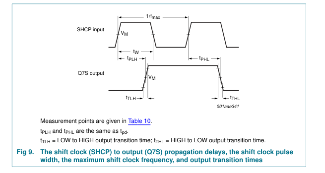
propagation SHCP to Q7S; tpd delay
see Figure 9 VCC = 2.0 V
- 44 150 - 185 - 225 ns
VCC = 4.5 V
- 16 30 - 37 - 45 ns
VCC = 5.0 V;
- 13 - - - - - ns
CL = 15 pF VCC = 6.0 V
- 14 26 - 31 - 38 ns
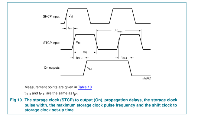
STCP to Qn; see Figure 10 VCC = 2.0 V
- 44 150 - 185 - 225 ns
VCC = 4.5 V
- 16 30 - 37 - 45 ns
VCC = 5.0 V;
- 13 - - - - - ns
CL = 15 pF VCC = 6.0 V
- 14 26 - 31 - 38 ns
HIGH to
SHR to Q7S; see
tPHL LOW
Figure 13
propagation
VCC = 2.0 V
- 39 150 - 185 - 225 ns
delay
VCC = 4.5 V
- 14 30 - 37 - 45 ns
VCC = 5.0 V;
- 11 - - - - - ns
CL = 15 pF VCC = 6.0 V
- 12 26 - 31 - 38 ns
STR to Qn; see Figure 14 VCC = 2.0 V
- 39 125 - 155 - 185 ns
VCC = 4.5 V
- 14 25 - 31 - 37 ns
VCC = 5.0 V;
- 11 - - - - - ns
CL = 15 pF VCC = 6.0 V
- 12 21 - 26 - 31 ns
see Figure 9
HIGH to tTHL LOW output
Serial data output Q7S
transition
VCC = 2.0 V
- 19 75 - 95 - 110 ns
time
VCC = 4.5 V
- 7 15 - 19 - 22 ns
VCC = 6.0 V
- 6 13 - 16 - 19 ns
Parallel data outputs VCC = 2.0 V
- 14 60 - 75 - 90 ns
VCC = 4.5 V
- 5 12 - 15 - 18 ns
VCC = 6.0 V
- 4 10 - 13 - 15 ns
12 of 26
Page 13
Table 8. Dynamic characteristics type 74HC594 …continued GND = 0 V; tr = tf = 6 ns; CL = 50 pF; see Figure 15.
| Symbol Parameter Conditions | 25 °C | −40 °C to +85 °C | −40 °C to +125 °C | Unit | ||||
|---|---|---|---|---|---|---|---|---|
| Min | Typ | Max | Min | Max | Min | Max | ||
see Figure 9
tTLH LOW to HIGH output
Serial data output Q7S
transition
VCC = 2.0 V
- 19 75 - 95 - 110 ns
time
VCC = 4.5 V
- 7 15 - 19 - 22 ns
VCC = 6.0 V
- 6 13 - 16 - 19 ns
Parallel data outputs VCC = 2.0 V
- 14 60 - 75 - 90 ns
VCC = 4.5 V
- 5 12 - 15 - 18 ns
VCC = 6.0 V
- 4 10 - 13 - 15 ns
pulse width SHCP (HIGH or tW
LOW); see Figure 9 VCC = 2.0 V
80 10 - 100 - 120 - ns
VCC = 4.5 V
16 4 - 20 - 24 - ns
VCC = 6.0 V
14 3 - 17 - 20 - ns
STCP (HIGH or LOW); see Figure 10 VCC = 2.0 V
80 10 - 100 - 120 - ns
VCC = 4.5 V
16 4 - 20 - 24 - ns
VCC = 6.0 V
14 3 - 17 - 20 - ns
SHR and STR (HIGH or LOW); see Figure 13 and Figure 14 VCC = 2.0 V
80 14 - 100 - 120 - ns
VCC = 4.5 V
16 5 - 20 - 24 - ns
VCC = 6.0 V
14 4 - 17 - 20 - ns
13 of 26
Page 14
Table 8. Dynamic characteristics type 74HC594 …continued GND = 0 V; tr = tf = 6 ns; CL = 50 pF; see Figure 15.
| Symbol Parameter Conditions | 25 °C | −40 °C to +85 °C | −40 °C to +125 °C | Unit | ||||
|---|---|---|---|---|---|---|---|---|
| Min | Typ | Max | Min | Max | Min | Max | ||
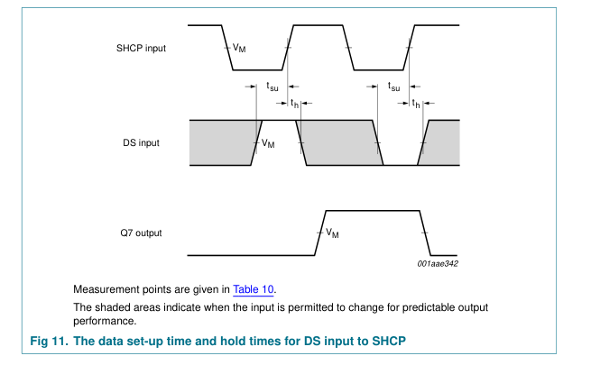
tsu set-up time DS to SHCP;
see Figure 11 VCC = 2.0 V
100 10 - 125 - 150 - ns
VCC = 4.5 V
20 4 - 25 - 30 - ns
VCC = 6.0 V
17 3 - 21 - 26 - ns
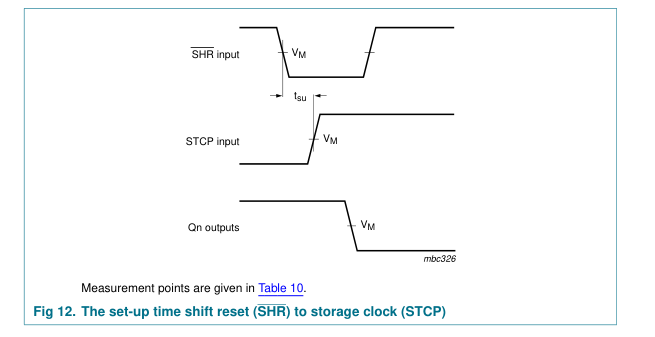
SHR to STCP; see Figure 12 VCC = 2.0 V
100 14 - 125 - 150 - ns
VCC = 4.5 V
20 5 - 25 - 30 - ns
VCC = 6.0 V
17 4 - 21 - 26 - ns
SHCP to STCP; see Figure 10 VCC = 2.0 V
100 17 - 125 - 150 - ns
VCC = 4.5 V
20 6 - 25 - 30 - ns
VCC = 6.0 V
17 5 - 21 - 26 - ns
hold time
DS to SHCP;
th
see Figure 11 VCC = 2.0 V
25 −8 - 30 - 35 - ns
VCC = 4.5 V
5 −3 - 6 - 7 - ns
VCC = 6.0 V
4 −2 - 5 - 6 - ns
recovery
SHR to SHCP
trec time
and STR to STCP; see Figure 13 and Figure 14 VCC = 2.0 V
50 −14 - 65 - 75 - ns
VCC = 4.5 V
10 −5 - 13 - 15 - ns
VCC = 6.0 V
9 −4 - 11 - 13 - ns
maximum
SHCP or STCP;
fmax frequency
see Figure 9 and Figure 10 VCC = 2.0 V
6.0 30 - 4.8 - 4.0 - MHz
VCC = 4.5 V
30 92 - 24 - 20 - MHz
VCC = 5.0 V;
- 100 - - - - - MHz
CL = 15 pF VCC = 6.0 V
35 109 - 28 - 24 - MHz
14 of 26
Page 15
Table 8. Dynamic characteristics type 74HC594 …continued GND = 0 V; tr = tf = 6 ns; CL = 50 pF; see Figure 15.
| Symbol Parameter Conditions | 25 °C | −40 °C to +85 °C | −40 °C to +125 °C | Unit | ||||
|---|---|---|---|---|---|---|---|---|
| Min | Typ | Max | Min | Max | Min | Max | ||
[2]
VI = GND to VCC;
CPD power
- 84 - - - - - pF
dissipation VCC = 5 V; capacitance fi = 1 MHz
[1] tpd is the same as tPHL and tPLH. [2] CPD is used to determine the dynamic power dissipation (PD in µW): PD = CPD × VCC2 × fi × N + ∑(CL × VCC2 × fo) where: fi = input frequency in MHz; fo = output frequency in MHz; CL = output load capacitance in pF; VCC = supply voltage in V; N = number of inputs switching; ∑(CL × VCC2 × fo) = sum of outputs.
Table 9. Dynamic characteristics type 74HCT594 GND = 0 V; VCC = 4.5 V; tr = tf = 6 ns; CL = 50 pF; see Figure 15.
| Symbol Parameter Conditions | 25 °C | −40 °C to +85 °C | −40 °C to +125 °C | Unit | ||||
|---|---|---|---|---|---|---|---|---|
| Min | Typ | Max | Min | Max | Min | Max | ||
[1]
propagation SHCP to Q7S;
- 18 32 - 40 - 48 ns
tpd delay
see Figure 9 VCC = 5.0 V;
- 15 - - - - - ns
CL = 15 pF
- 18 32 - 40 - 48 ns
STCP to Qn; see Figure 10 VCC = 5.0 V;
- 15 - - - - - ns
CL = 15 pF
HIGH to
SHR to Q7S; see
- 17 30 - 38 - 45 ns
tPHL LOW
Figure 13
propagation
VCC = 5.0 V;
- 14 - - - - - ns
delay
CL = 15 pF STR to Qn; see
- 17 30 - 38 - 45 ns
Figure 14 VCC = 5.0 V;
- 14 - - - - - ns
CL = 15 pF see Figure 9
HIGH to tTHL LOW output
Serial data output Q7S
transition
VCC = 4.5 V
- 7 15 - 19 - 22 ns
time
Parallel data outputs VCC = 4.5 V
- 5 12 - 15 - 18 ns
see Figure 9
LOW to tTLH HIGH output
Serial data output Q7S
transition
VCC = 4.5 V
- 7 15 - 19 - 22 ns
time
Parallel data outputs VCC = 4.5 V
- 5 12 - 15 - 18 ns
15 of 26
Page 16
Table 9. Dynamic characteristics type 74HCT594 …continued GND = 0 V; VCC = 4.5 V; tr = tf = 6 ns; CL = 50 pF; see Figure 15.
| Symbol Parameter Conditions | 25 °C | −40 °C to +85 °C | −40 °C to +125 °C | Unit | ||||
|---|---|---|---|---|---|---|---|---|
| Min | Typ | Max | Min | Max | Min | Max | ||
16 4 - 20 - 24 - ns
tW pulse width SHCP (HIGH or
LOW); see Figure 9 STCP (HIGH or
16 4 - 20 - 24 - ns
LOW); see Figure 10
16 6 - 20 - 24 - ns
SHR and STR (HIGH or LOW); see Figure 13 and Figure 14
tsu set-up time DS to SHCP;
20 4 - 25 - 30 - ns
see Figure 11 SHR to STCP;
20 6 - 25 - 30 - ns
see Figure 12
20 7 - 25 - 30 - ns
SHCP to STCP; see Figure 10
hold time
DS to SHCP;
5 −3 - 6 - 7 - ns
th
see Figure 11
10 −5 - 13 - 15 - ns
recovery
SHR to SHCP
trec time
and STR to STCP; see Figure 13 and Figure 14
maximum
SHCP or STCP;
fmax
30 92 - 24 - 20 - MHz
frequency
see Figure 9 and Figure 10 VCC = 5.0 V;
- 100 - - - - - MHz
CL = 15 pF
[2]
VI = GND to VCC
power
- 89 - - - - - pF
CPD dissipation − 1.5 V; capacitance VCC = 5 V;
fi = 1 MHz
[1] tpd is the same as tPHL and tPLH. [2] CPD is used to determine the dynamic power dissipation (PD in µW): PD = CPD × VCC2 × fi × N + ∑(CL × VCC2 × fo) where: fi = input frequency in MHz; fo = output frequency in MHz; CL = output load capacitance in pF; VCC = supply voltage in V; N = number of inputs switching; ∑(CL × VCC2 × fo) = sum of outputs.
16 of 26
Page 17
12. Waveforms
17 of 26
Page 18
18 of 26
Page 19
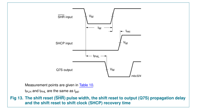
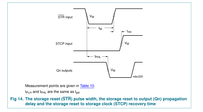
Table 10. Measurement points
| Type | Input | Output |
|---|---|---|
| V M | V M |
74HC594
0.5 × VCC
0.5 × VCC
74HCT594
1.3 V
1.3 V
19 of 26
Page 20
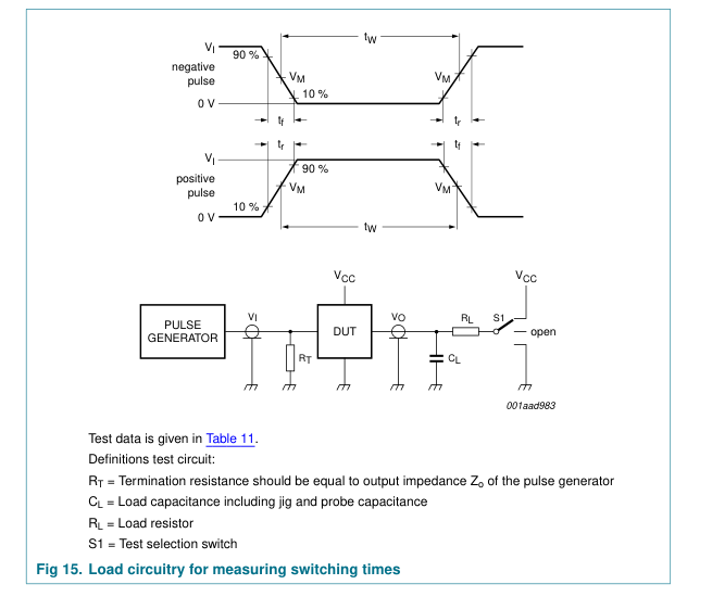
Table 11. Test data
| Type | Input | Load | S1 position | ||||
|---|---|---|---|---|---|---|---|
| V I | t, t r f | C L | R L | t , t PHL PLH | t , t PZH PHZ | t , t PZL PLZ | |
74HC594
VCC 6 ns 15 pF, 50 pF
1 kΩ open
GND
VCC
74HCT594
3 V 6 ns 15 pF, 50 pF
1 kΩ open
GND
VCC
20 of 26
Page 21
13. Package outline
SO16: plastic small outline package; 16 leads; body width 3.9 mm
SOT109-1
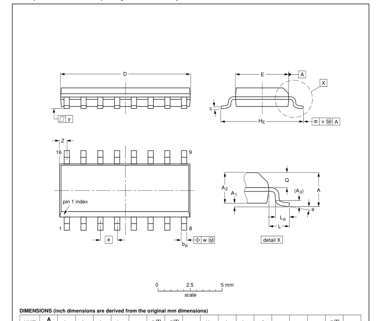

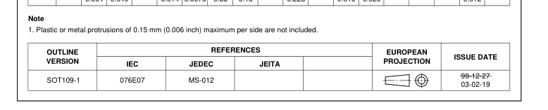
Fig 16. Package outline SOT109-1 (SO16)
21 of 26
Page 22
SSOP16: plastic shrink small outline package; 16 leads; body width 5.3 mm
SOT338-1
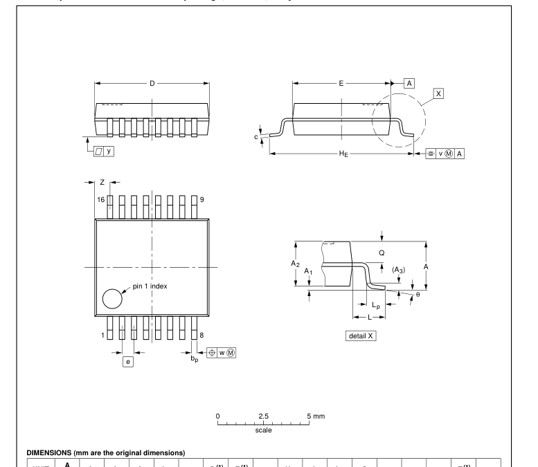

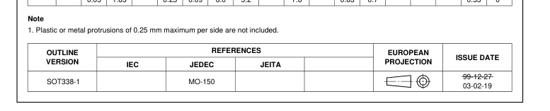
Fig 17. Package outline SOT338-1 (SSOP16)
22 of 26
Page 23
DIP16: plastic dual in-line package; 16 leads (300 mil)
SOT38-4
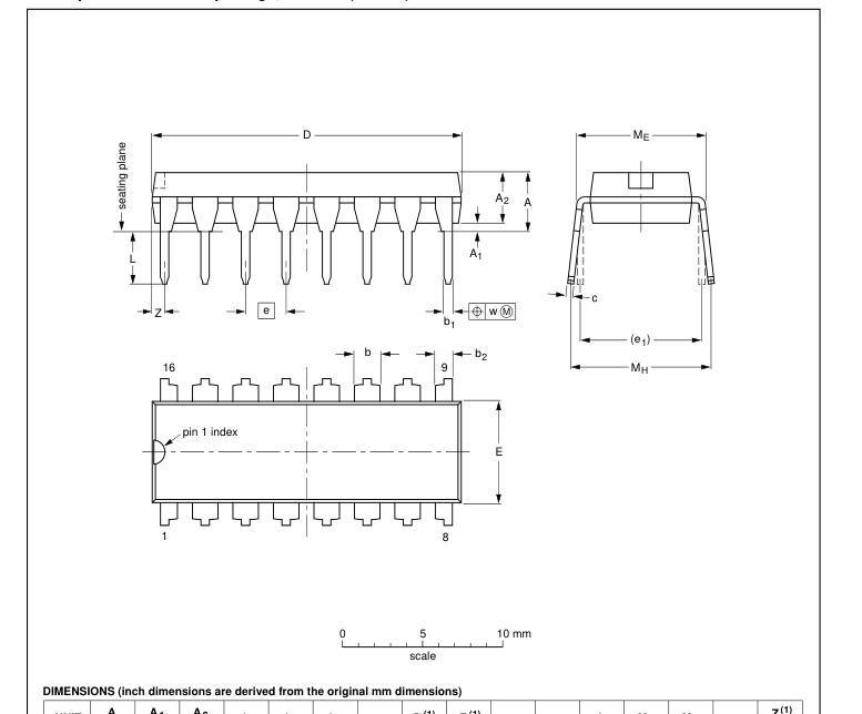

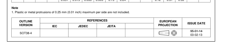
Fig 18. Package outline SOT38-4 (DIP16)
23 of 26
Page 24
14. Abbreviations
Table 12. Abbreviations Acronym
Description
CMOS
Complementary Metal Oxide Semiconductor
DUT
Device Under Test
ESD
ElectroStatic Discharge
HBM
Human Body Model
LSTTL
Low-Power Schottky Transistor-Transistor Logic
MM
Machine Model
TTL
Transistor-Transistor Logic
15. Revision history
Table 13. Revision history Document ID
Release date
Data sheet status
Change notice
Supersedes
20061220
-
74HC_HCT594_CNV_2
- The format of this data sheet has been redesigned to comply with the new identity guidelines
Modifications:
of NXP Semiconductors.
- Legal texts have been adapted to the new company name where appropriate.
- Table 1 “Ordering information” updated.
74HC_HCT594_CNV_2 19970908
Product specification -
74HC_HCT594_CNV_1
24 of 26
Page 25
16. Legal information
16.1 Data sheet status
Document status[1][2]
Product status[3]
Definition This document contains data from the objective specification for product development.
Objective [short] data sheet
Development
This document contains data from the preliminary specification.
Preliminary [short] data sheet Qualification
This document contains the product specification.
Product [short] data sheet
Production
[1] Please consult the most recently issued document before initiating or completing a design. [2] The term ‘short data sheet’ is explained in section “Definitions”. [3] The product status of device(s) described in this document may have changed since this document was published and may differ in case of multiple devices. The latest product status information is available on the Internet at URL http://www.nxp.com.
16.2 Definitions
Draft — The document is a draft version only. The content is still under internal review and subject to formal approval, which may result in modifications or additions. NXP Semiconductors does not give any representations or warranties as to the accuracy or completeness of information included herein and shall have no liability for the consequences of use of such information. Short data sheet — A short data sheet is an extract from a full data sheet with the same product type number(s) and title. A short data sheet is intended for quick reference only and should not be relied upon to contain detailed and full information. For detailed and full information see the relevant full data
sheet, which is available on request via the local NXP Semiconductors sales office. In case of any inconsistency or conflict with the short data sheet, the full data sheet shall prevail.
16.3 Disclaimers
General — Information in this document is believed to be accurate and reliable. However, NXP Semiconductors does not give any representations or warranties, expressed or implied, as to the accuracy or completeness of such information and shall have no liability for the consequences of use of such information. Right to make changes — NXP Semiconductors reserves the right to make changes to information published in this document, including without limitation specifications and product descriptions, at any time and without notice. This document supersedes and replaces all information supplied prior to the publication hereof. Suitability for use — NXP Semiconductors products are not designed,
authorized or warranted to be suitable for use in medical, military, aircraft, space or life support equipment, nor in applications where failure or
17. Contact information
For additional information, please visit: http://www.nxp.com
malfunction of a NXP Semiconductors product can reasonably be expected to result in personal injury, death or severe property or environmental damage. NXP Semiconductors accepts no liability for inclusion and/or use of NXP Semiconductors products in such equipment or applications and therefore such inclusion and/or use is at the customer’s own risk. Applications — Applications that are described herein for any of these products are for illustrative purposes only. NXP Semiconductors makes no representation or warranty that such applications will be suitable for the specified use without further testing or modification. Limiting values — Stress above one or more limiting values (as defined in
the Absolute Maximum Ratings System of IEC 60134) may cause permanent damage to the device. Limiting values are stress ratings only and operation of the device at these or any other conditions above those given in the Characteristics sections of this document is not implied. Exposure to limiting values for extended periods may affect device reliability. Terms and conditions of sale — NXP Semiconductors products are sold subject to the general terms and conditions of commercial sale, as published at http://www.nxp.com/profile/terms, including those pertaining to warranty, intellectual property rights infringement and limitation of liability, unless explicitly otherwise agreed to in writing by NXP Semiconductors. In case of
any inconsistency or conflict between information in this document and such terms and conditions, the latter will prevail. No offer to sell or license — Nothing in this document may be interpreted or construed as an offer to sell products that is open for acceptance or the grant, conveyance or implication of any license under any copyrights, patents or other industrial or intellectual property rights.
16.4 Trademarks
Notice: All referenced brands, product names, service names and trademarks are the property of their respective owners.
For sales office addresses, send an email to: salesaddresses@nxp.com
25 of 26
Page 26
18. Contents
1 General description . . . . . . . . . . . . . . . . . . . . . . 1 2 Features . . . . . . . . . . . . . . . . . . . . . . . . . . . . . . . 1 3 Applications . . . . . . . . . . . . . . . . . . . . . . . . . . . . 1 4 Ordering information . . . . . . . . . . . . . . . . . . . . . 2 5 Functional diagram . . . . . . . . . . . . . . . . . . . . . . 2 6 Pinning information. . . . . . . . . . . . . . . . . . . . . . 4 6.1 Pinning . . . . . . . . . . . . . . . . . . . . . . . . . . . . . . . 4 6.2 Pin description . . . . . . . . . . . . . . . . . . . . . . . . . 5 7 Functional description . . . . . . . . . . . . . . . . . . . 6 8 Limiting values. . . . . . . . . . . . . . . . . . . . . . . . . . 6
9 Recommended operating conditions. . . . . . . . 7 10 Static characteristics. . . . . . . . . . . . . . . . . . . . . 7 11 Dynamic characteristics . . . . . . . . . . . . . . . . . 12 12 Waveforms . . . . . . . . . . . . . . . . . . . . . . . . . . . . 17 13 Package outline . . . . . . . . . . . . . . . . . . . . . . . . 21 14 Abbreviations. . . . . . . . . . . . . . . . . . . . . . . . . . 24 15 Revision history. . . . . . . . . . . . . . . . . . . . . . . . 24 16 Legal information. . . . . . . . . . . . . . . . . . . . . . . 25 16.1 Data sheet status . . . . . . . . . . . . . . . . . . . . . . 25 16.2 Definitions. . . . . . . . . . . . . . . . . . . . . . . . . . . . 25
16.3 Disclaimers . . . . . . . . . . . . . . . . . . . . . . . . . . . 25 16.4 Trademarks. . . . . . . . . . . . . . . . . . . . . . . . . . . 25 17 Contact information. . . . . . . . . . . . . . . . . . . . . 25 18 Contents . . . . . . . . . . . . . . . . . . . . . . . . . . . . . . 26

Please be aware that important notices concerning this document and the product(s) described herein, have been included in section ‘Legal information’.
© NXP B.V. 2006.
All rights reserved.
For more information, please visit: http://www.nxp.com For sales office addresses, please send an email to: salesaddresses@nxp.com
Date of release: 20 December 2006 Document identifier: 74HC_HCT594_3