Download PDF
74HC573 PHILIPS
Document overview
- PDF pages: 7
Technical content
Page 1
Page 2
Page 3
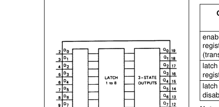
| PIN NO. | SYMBOL | NAME AND FUNCTION |
|---|---|---|
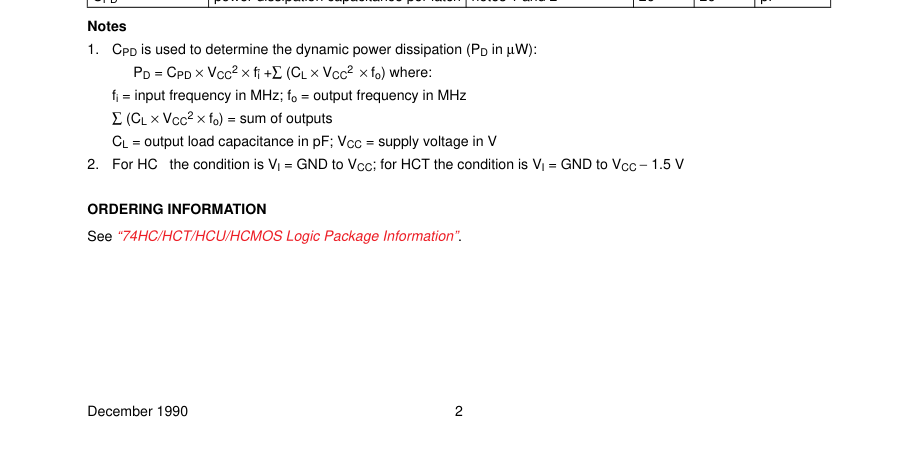
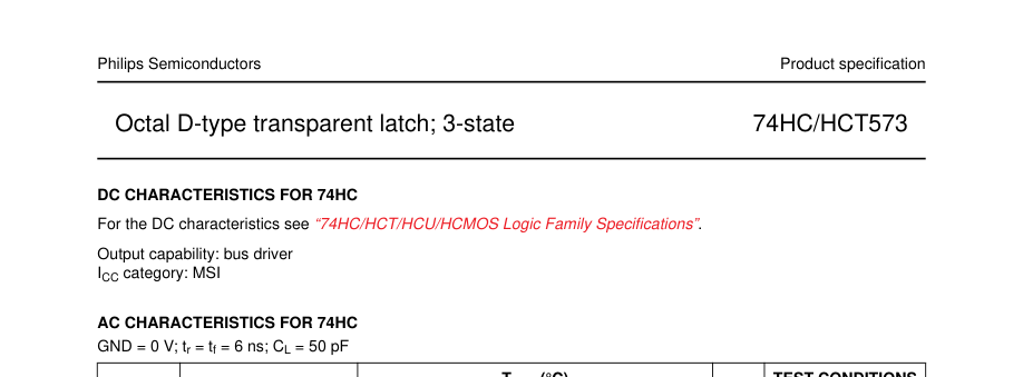
| 2, 3, 4, 5, 6, 7, 8, 9 11 1 10 19, 18, 17, 16, 15, 14, 13, 12 20 | D to D 0 7 LE OE GND Q to Q 0 7 V CC | data inputs latch enable input (active HIGH) 3-state output enable input (active LOW) ground (0 V) 3-state latch outputs positive supply voltage |
Page 4
| OPERATING MODES | INPUTS | INTERNAL LATCHES | OUTPUTS | ||
| OE | LE | D N | Q to Q 0 7 | ||
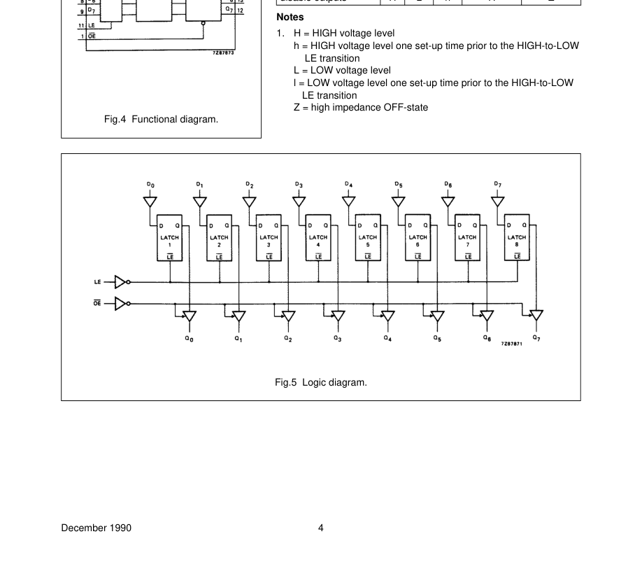
| enable and read register (transparent mode) | L L | H H | L H | L H | L H |
| latch and read register | L L | L L | l h | L H | L H |
| latch register and disable outputs | H H | L L | l h | L H | Z Z |
Page 5
Page 6


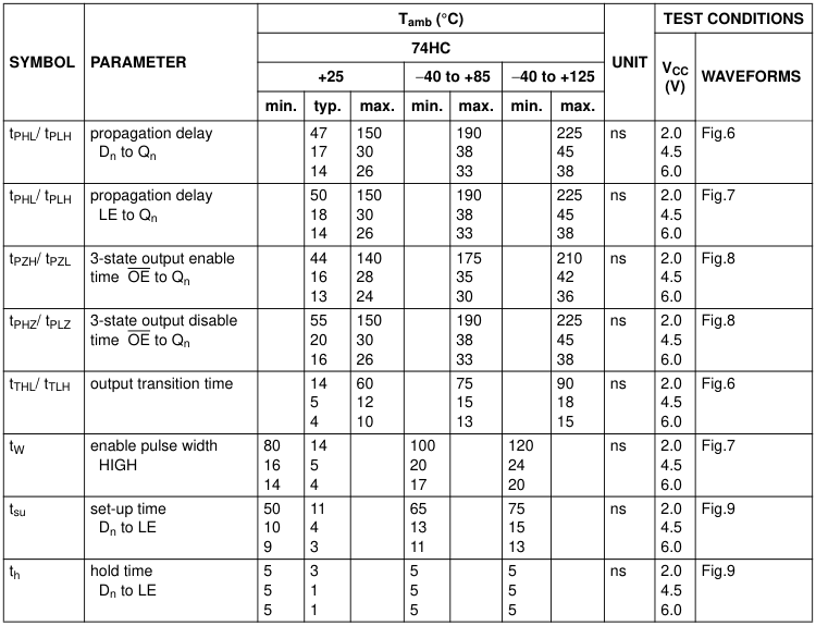
| SYMBOL | PARAMETER | T (°C) amb | UNIT | TEST CONDITIONS | |||||||
|---|---|---|---|---|---|---|---|---|---|---|---|
| 74HCT | V CC (V) | WAVEFORMS | |||||||||
| +25 | −40 to +85 | −40 to +125 | |||||||||
| min. | typ. | max. | min. | max. | min. | max. | |||||
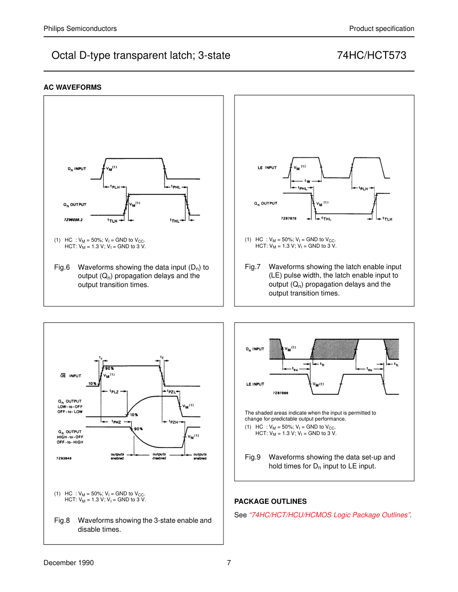
| t / t PHL PLH | propagation delay D to Q n n | 20 | 35 | 44 | 53 | ns | 4.5 | Fig.6 | |||
| t / t PHL PLH | propagation delay LE to Q n | 18 | 35 | 44 | 53 | ns | 4.5 | Fig.7 | |||
| t / t PZH PZL | 3-state output enable time OE to Q n | 17 | 30 | 38 | 45 | ns | 4.5 | Fig.8 | |||
| t / t PHZ PLZ | 3-state output disable time OE to Q n | 18 | 30 | 38 | 45 | ns | 4.5 | Fig.8 | |||
| t / t THL TLH | output transition time | 5 | 12 | 15 | 18 | ns | 4.5 | Fig.6 | |||
| t W | enable pulse width HIGH | 16 | 5 | 20 | 24 | ns | 4.5 | Fig.7 | |||
| t su | set-up time D to LE n | 13 | 7 | 16 | 20 | ns | 4.5 | Fig.9 | |||
| t h | hold time D to LE n | 9 | 4 | 11 | 14 | ns | 4.5 | Fig.9 | |||
Page 7