Download PDF
74HC42 PHILIPS
Document overview
- PDF pages: 6
Technical content
Page 1
Page 2
FEATURES
- Mutually exclusive outputs
- 1-of-8 demultiplexing capability
- Outputs disabled for input codes above nine
- Output capability: standard
- ICC category: MSI
GENERAL DESCRIPTION
The 74HC/HCT42 are high-speed Si-gate CMOS devices and are pin compatible with low power Schottky TTL (LSTTL). They are specified in compliance with JEDEC standard no. 7A.
QUICK REFERENCE DATA
GND = 0 V; Tamb = 25 °C; tr = tf = 6 ns
The 74HC/HCT42 decoders accept four active HIGH BCD inputs and provide 10 mutually exclusive active LOW outputs. The active LOW outputs facilitate addressing other MSI circuits with active LOW input enables. The logic design of the “42” ensures that all outputs are HIGH when binary codes greater than nine are applied to the inputs. The most significant input (A3) produces an useful inhibit function when the “42” is used as a 1-of-8 decoder. The A3 input can also be used as the data input in an 8-output demultiplexer application.
| SYMBOL | PARAMETER | CONDITIONS | TYPICAL | UNIT | |
|---|---|---|---|---|---|
| HC | HCT | ||||
| t / t PHL PLH | propagation delay A to Y n n | C = 15 pF; V = 5 V L CC | 14 | 17 | ns |
| C I | input capacitance | 3.5 | 3.5 | pF | |
| C PD | power dissipation capacitance per package | notes 1 and 2 | 37 | 37 | pF |
Notes 1. CPD is used to determine the dynamic power dissipation (PD in µW): PD = CPD × VCC2 × fi + ∑ (CL × VCC2 × fo) where: fi = input frequency in MHz fo = output frequency in MHz ∑ (CL × VCC2 × fo) = sum of outputs CL = output load capacitance in pF VCC = supply voltage in V 2. For HC the condition is VI = GND to VCC For HCT the condition is VI = GND to VCC − 1.5 V
ORDERING INFORMATION
See “74HC/HCT/HCU/HCMOS Logic Package Information”.
Page 3
PIN DESCRIPTION
| PIN NO. | SYMBOL | NAME AND FUNCTION |
|---|---|---|
| 1, 2, 3, 4, 5, 6, 7, 9, 10, 11 8 15, 14, 13, 12 16 | Y to Y 0 9 GND A to A 0 3 V CC | multiplexer outputs ground (0 V) data inputs positive supply voltage |
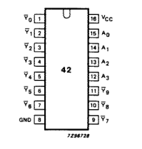
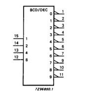
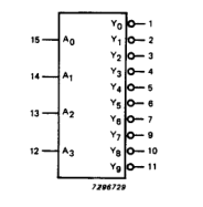
Fig.2 Logic symbol.
Fig.1 Pin configuration.
Fig.3 IEC logic symbol.
Page 4
FUNCTION TABLE
| Column 1 | Column 2 | Column 3 | Column 4 | Column 5 | Column 6 | Column 7 | Column 8 | Column 9 | Column 10 | Column 11 | Column 12 | Column 13 | Column 14 |
|---|---|---|---|---|---|---|---|---|---|---|---|---|---|
| INPUTS | OUTPUTS | ||||||||||||
| A 3 | A 2 | A 1 | A 0 | Y 0 | Y 1 | Y 2 | Y 3 | Y 4 | Y 5 | Y 6 | Y 7 | Y 8 | Y 9 |
| L L L L | L L L L | L L H H | L H L H | L H H H | H L H H | H H L H | H H H L | H H H H | H H H H | H H H H | H H H H | H H H H | H H H H |
| L L L L | H H H H | L L H H | L H L H | H H H H | H H H H | H H H H | H H H H | L H H H | H L H H | H H L H | H H H L | H H H H | H H H H |
| H H H H | L L L L | L L H H | L H L H | H H H H | H H H H | H H H H | H H H H | H H H H | H H H H | H H H H | H H H H | L H H H | H L H H |
| H H H H | H H H H | L L H H | L H L H | H H H H | H H H H | H H H H | H H H H | H H H H | H H H H | H H H H | H H H H | H H H H | H H H H |
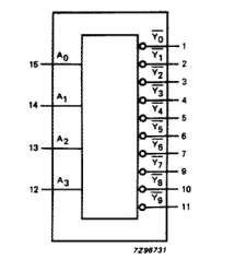
Fig.4 Functional diagram.
Note 1. H = HIGH voltage level L = LOW voltage level
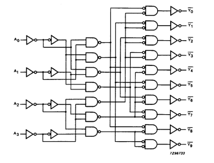
Fig.5 Logic diagram.
Page 5
DC CHARACTERISTICS FOR 74HC
For the DC characteristics see “74HC/HCT/HCU/HCMOS Logic Family Specifications”. Output capability: standard ICC category: MSI
AC CHARACTERISTICS FOR 74HC
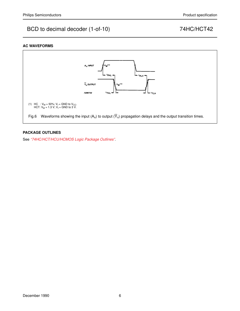
GND = 0 V; tr = tf = 6 ns; CL = 50 pF
| SYMBOL | PARAMETER | T (°C) amb | UNIT | TEST CONDITIONS | |||||||
|---|---|---|---|---|---|---|---|---|---|---|---|
| 74HC | V CC (V) | WAVEFORMS | |||||||||
| +25 | −40 to +85 | −40 to +125 | |||||||||
| min. | typ. | max. | min. | max. | min. | max. | |||||
| t / t PHL PLH | propagation delay A to Y n n | 47 17 14 | 150 30 26 | 190 38 33 | 225 45 38 | ns | 2.0 4.5 6.0 | Fig.6 | |||
| t / t THL TLH | output transition time | 19 7 6 | 75 15 13 | 95 19 16 | 110 22 19 | ns | 2.0 4.5 6.0 | Fig.6 |
DC CHARACTERISTICS FOR 74HCT
For the DC characteristics see “74HC/HCT/HCU/HCMOS Logic Family Specifications”. Output capability: standard ICC category: MSI
Note to HCT types The value of additional quiescent supply current (∆ICC) for a unit load of 1 is given in the family specifications. To determine ∆ICC per input, multiply this value by the unit load coefficient shown in the table below.
| INPUT | UNIT LOAD COEFFICIENT |
|---|---|
| A n | 1.0 |
AC CHARACTERISTICS FOR 74HCT
GND = 0 V; tr = tf = 6 ns; CL = 50 pF
| SYMBOL | PARAMETER | T (°C) amb | UNIT | TEST CONDITIONS | |||||||
|---|---|---|---|---|---|---|---|---|---|---|---|
| 74HCT | V CC (V) | WAVEFORMS | |||||||||
| +25 | −40 to +85 | −40 to +125 | |||||||||
| min. | typ. | max. | min. | max. | min. | max. | |||||
| t / t PHL PLH | propagation delay A to Y n n | 20 | 35 | 44 | 53 | ns | 4.5 | Fig.6 | |||
| t / t THL TLH | output transition time | 7 | 15 | 19 | 22 | ns | 4.5 | Fig.6 |
Page 6