74HC4024 PHILIPS
Document overview
- PDF pages: 7
Technical content
Page 1
Page 2
FEATURES
- Output capability: standard
- ICC category: MSI
GENERAL DESCRIPTION
The 74HC/HCT4024 are high-speed Si-gate CMOS devices and are pin compatible with the “4024” of the “4000B” series. They are specified in compliance with JEDEC standard no. 7A. The 74HC/HCT4024 are 7-stage binary ripple counters with a clock input (CP), an overriding asynchronous master reset input (MR) and seven fully buffered parallel outputs (Q0 to Q6).
QUICK REFERENCE DATA
GND = 0 V; Tamb = 25 °C; tr = tf = 6 ns
The counter advances on the HIGH-to-LOW transition of CP. A HIGH on MR clears all counter stages and forces all outputs LOW, independent of the state of CP. Each counter stage is a static toggle flip-flop. Schmitt-trigger action in the clock input makes the circuit highly tolerant to slower clock rise and fall times.
APPLICATIONS
- Frequency dividing circuits
- Time delay circuits
| SYMBOL | PARAMETER | CONDITIONS | TYPICAL | UNIT | |
|---|---|---|---|---|---|
| HC | HCT | ||||
| t / t PHL PLH | propagation delay CP to Q 0 | C = 15 pF; V = 5 V L CC | 14 | 14 | ns |
| f max | maximum clock frequency | 90 | 70 | MHz | |
| C I | input capacitance | 3.5 | 3.5 | pF | |
| C PD | power dissipation capacitance per package | notes 1 and 2 | 25 | 27 | pF |
Notes 1. CPD is used to determine the dynamic power dissipation (PD in µW): PD = CPD × VCC2 × fi + ∑ (CL × VCC2 × fo) where: fi = input frequency in MHz fo = output frequency in MHz ∑ (CL × VCC2 × fo) = sum of outputs CL = output load capacitance in pF VCC = supply voltage in V 2. For HC the condition is VI = GND to VCC For HCT the condition is VI = GND to VCC − 1.5 V
ORDERING INFORMATION
See “74HC/HCT/HCU/HCMOS Logic Package Information”.
Page 3
PIN DESCRIPTION
| PIN NO. | SYMBOL | NAME AND FUNCTION |
|---|---|---|
| 1 2 12, 11, 9, 6, 5, 4, 3 7 8, 10, 13 14 | CP MR Q to Q 0 6 GND n.c. V CC | clock input (HIGH-to-LOW, edge-triggered) master reset input (active HIGH) parallel outputs ground (0 V) not connected positive supply voltage |
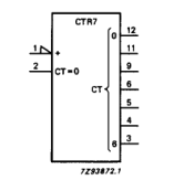
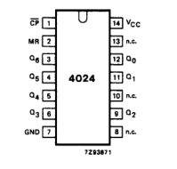
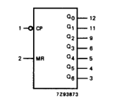
Fig.2 Logic symbol.
Fig.1 Pin configuration.
Fig.3 IEC logic symbol.
Page 4
FUNCTION TABLE
| Column 1 | Column 2 | Column 3 |
|---|---|---|
| INPUTS | OUTPUTS | |
| CP | MR | Q n |
| ↑ ↓ X | L L H | no change count L |
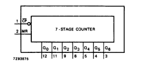
Notes 1. H = HIGH voltage level L = LOW voltage level X = don’t care ↑ = LOW-to-HIGH clock transition ↓= HIGH-to-LOW clock transition
Fig.4 Functional diagram.
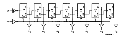
Fig.5 Logic diagram.
Page 5
DC CHARACTERISTICS FOR 74HC
For the DC characteristics see “74HC/HCT/HCU/HCMOS Logic Family Specifications”. Output capability: standard ICC category: MSI
AC CHARACTERISTICS FOR 74HC
GND = 0 V; tr = tf = 6 ns; CL = 50 pF
| SYMBOL | PARAMETER | T (°C) amb | UNIT | TEST CONDITIONS | |||||||
|---|---|---|---|---|---|---|---|---|---|---|---|
| 74HC | V CC (V) | WAVEFORMS | |||||||||
| +25 | −40 to +125 | −40 to +125 | |||||||||
| min. | typ. | max. | min. | max. | min. | max. | |||||
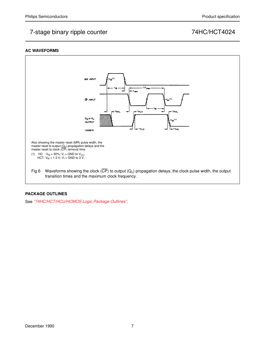
| t / t PHL PLH | propagation delay CP to Q 0 | 47 17 14 | 175 35 30 | 220 44 37 | 265 53 45 | ns | 2.0 4.5 6.0 | Fig.6 | |||
| t PHL | propagation delay MR to Q 0 | 63 23 18 | 200 40 34 | 250 50 43 | 300 60 51 | ns | 2.0 4.5 6.0 | Fig.6 | |||
| t / t PHL PLH | propagation delay Q to Q n n+1 | 25 9 7 | 80 16 14 | 100 20 17 | 120 24 20 | ns | 2.0 4.5 6.0 | Fig.6 | |||
| t / t THL TLH | output transition time | 19 7 6 | 75 15 13 | 95 19 16 | 110 22 19 | ns | 2.0 4.5 6.0 | Fig.6 | |||
| t W | clock pulse width HIGH or LOW | 80 16 14 | 17 6 5 | 100 20 17 | 120 24 20 | ns | 2.0 4.5 6.0 | Fig.6 | |||
| t W | master reset pulse width HIGH | 80 16 14 | 22 8 6 | 100 20 17 | 120 24 20 | ns | 2.0 4.5 6.0 | Fig.6 | |||
| t rem | removal time MR to CP | 50 10 9 | 6 2 2 | 65 13 11 | 75 15 13 | ns | 2.0 4.5 6.0 | Fig.6 | |||
| f max | maximum clock pulse frequency | 6.0 30 35 | 27 82 98 | 4.8 24 28 | 4.0 20 24 | MHz | 2.0 4.5 6.0 | Fig.6 |
Page 6
DC CHARACTERISTICS FOR 74HCT
For the DC characteristics see “74HC/HCT/HCU/HCMOS Logic Family Specifications”. Output capability: standard ICC category: MSI
Note to HCT types The value of additional quiescent supply current (∆ICC) for a unit load of 1 is given in the family specifications. To determine ∆ICC per input, multiply this value by the unit load coefficient shown in the table below.
| INPUT | UNIT LOAD COEFFICIENT |
|---|---|
| CP MR | 0.75 0.85 |
AC CHARACTERISTICS FOR 74HCT
GND = 0 V; tr = tf = 6 ns; CL = 50 pF
| SYMBOL | PARAMETER | T (°C) amb | UNIT | TEST CONDITIONS | |||||||
|---|---|---|---|---|---|---|---|---|---|---|---|
| 74HCT | V CC (V) | WAVEFORMS | |||||||||
| +25 | −40 to +125 | −40 to +125 | |||||||||
| min. | typ. | max. | min. | max. | min. | max. | |||||
| t / t PHL PLH | propagation delay CP to Q 0 | 17 | 35 | 44 | 53 | ns | 4.5 | Fig.6 | |||
| t PHL | propagation delay MR to Q 0 | 21 | 40 | 50 | 60 | ns | 4.5 | Fig.6 | |||
| t / t PHL PLH | propagation delay Q to Q n n+1 | 9 | 16 | 20 | 24 | ns | 4.5 | Fig.6 | |||
| t / t THL TLH | output transition time | 7 | 15 | 19 | 22 | ns | 4.5 | Fig.6 | |||
| t W | clock pulse width HIGH or LOW | 16 | 9 | 20 | 24 | ns | 4.5 | Fig.6 | |||
| t W | master reset pulse width HIGH | 16 | 6 | 20 | 24 | ns | 4.5 | Fig.6 | |||
| t rem | removal time MR to CP | 10 | 0 | 13 | 15 | ns | 4.5 | Fig.6 | |||
| f max | maximum clock pulse frequency | 30 | 64 | 24 | 20 | MHz | 4.5 | Fig.6 |
Page 7