

74HC40105 PHILIPS
Document overview
- PDF pages: 25
Technical content
Page 1
INTEGRATED CIRCUITS

Page 2

FEATURES
- Independent asynchronous inputs and outputs
- Expandable in either direction
- Reset capability
- Status indicators on inputs and outputs
- 3-state outputs
- Output capability: standard
- ICC category: MSI
GENERAL DESCRIPTION
The 74HC/HCT40105 are high-speed Si-gate CMOS devices and are pin compatible with the “40105” of the “4000B” series. They are specified in compliance with JEDEC standard no. 7A. The 74HC/HCT40105 are first-in/first-out (FIFO) “elastic” storage registers that can store sixteen 4-bit words. The “40105” is capable of handling input and output data at
QUICK REFERENCE DATA
GND = 0 V; Tamb = 25 °C; tr = tf = 6 ns
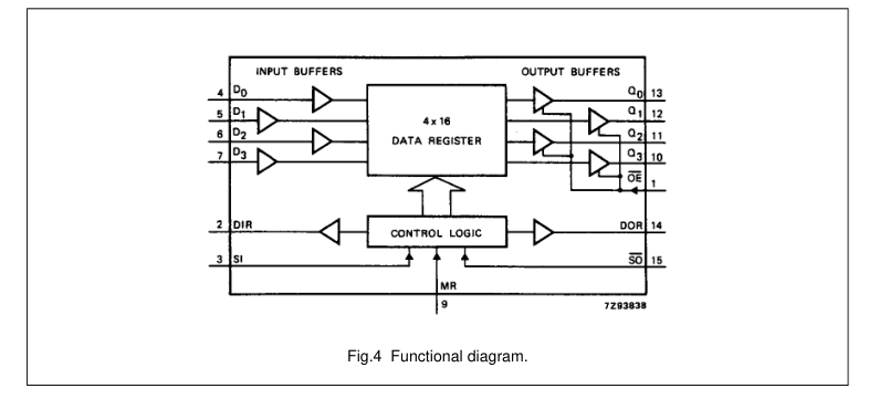
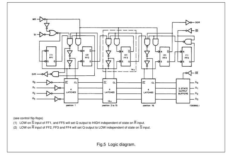
different shifting rates. This feature makes it particularly useful as a buffer between asynchronous systems. Each word position in the register is clocked by a control flip-flop, which stores a marker bit. A “1” signifies that the position’s data is filled and a “0” denotes a vacancy in that position. The control flip-flop detects the state of the preceding flip-flop and communicates its own status to the succeeding flip-flop. When a control flip-flop is in the “0” state and sees a “1” in the preceding flip-flop, it generates a clock pulse that transfers data from the preceding four data latches into its own four data latches and resets the preceding flip-flop to “0”. The first and last control flip-flops
have buffered outputs. Since all empty locations “bubble” automatically to the input end, and all valid data ripples through to the output end, the status of the first control flip-flop (data-in ready output - DIR) indicates if the FIFO is full, and the status of the last flip-flop (data-out ready output - DOR) indicates if the FIFO contains data. As the earliest data is removed from the bottom of the data stack (output end), all data entered later will automatically ripple toward the output.
| SYMBOL | PARAMETER | CONDITIONS | TYP. | UNIT | |
|---|---|---|---|---|---|
| HC | HCT | ||||
| t / t PHL PLH | propagation delay MR to DIR, DOR SO to Q n | C = 15 pF; V = 5 V L CC | 16 37 | 15 35 | ns ns |
| t PHL | propagation delay SI to DIR SO to DOR | 16 17 | 18 18 | ns ns | |
| f max | maximum clock frequency | 33 | 31 | MHz | |
| C I | input capacitance | 3.5 | 3.5 | pF | |
| C PD | power dissipation capacitance per package | notes 1 and 2 | 134 | 145 | pF |
Notes 1. CPD is used to determine the dynamic power dissipation (PD in µW): PD = CPD × VCC2 × fi + ∑ (CL × VCC2 × fo) where: fi = input frequency in MHz. fo = output frequency in MHz. ∑ (CL × VCC2 × fo) = sum of outputs CL = output load capacitance in pF VCC = supply voltage in V 2. For HC the condition is VI = GND to VCC For HCT the condition is VI = GND to VCC − 1.5
Page 3

ORDERING INFORMATION
| TYPE NUMBER | PACKAGE | ||
|---|---|---|---|
| NAME | DESCRIPTION | VERSION | |
| 74HC(T)40105N | DIP16 | plastic dual in-line package; 16 leads (300 mil); long body | SOT38-1 |
| 74HC(T)40105D | SO16 | plastic small outline package; 16 leads; body width 3.9 mm | SOT109-1 |
| 74HC(T)40105DB | SSOP16 | plastic shrink small outline package; 16 leads; body width 5.3 mm | SOT338-1 |
| 74HC(T)40105PW | TSSOP16 | plastic thin shrink small outline package; 16 leads; body width 4.4 mm | SOT403-1 |
PIN DESCRIPTION
| PIN NO. | SYMBOL | NAME AND FUNCTION |
|---|---|---|
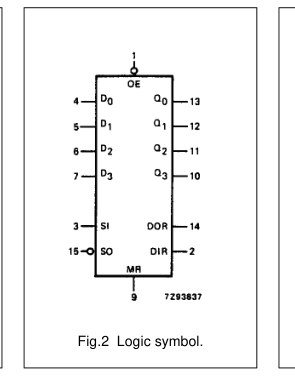
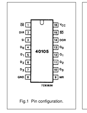
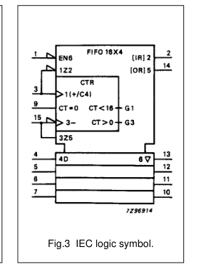
| 1 2 3 4, 5, 6, 7 8 9 13, 12, 11, 10 14 15 16 | OE DIR SI D to D 0 3 GND MR Q to Q 0 3 DOR SO V CC | output enable input (active LOW) data-in ready output shift-in input (LOW-to-HIGH, edge-triggered) parallel data inputs ground (0 V) asynchronous master reset input (active HIGH) 3-state data outputs data-out ready output shift-out input (HIGH-to-LOW, edge-triggered) positive supply voltage |
Page 4

Shift-in control (SI)
INPUT AND OUTPUTS
Data is loaded into the input stage on
Data inputs (D0 to D3)
a LOW-to-HIGH transition of SI.
As there is no weighting of the inputs,
It also triggers an automatic data
any input can be assigned as the
transfer process (ripple through). If SI
MSB. The size of the FIFO memory
is held HIGH during reset, data will be
can be reduced from the 4 × 16
loaded at the falling edge of the MR
configuration, i.e. 3 × 16, down to
signal.
1 × 16, by tying unused data input pins to VCC or GND.
Shift-out control (SO) A HIGH-to-LOW transition of
Data outputs (Q0 to Q3)
SO causes the DOR flags to go LOW.
As there is no weighting of the
A HIGH-to-LOW transition of
outputs, any output can be assigned
SO causes upstream data to move
as the MSB. The size of the FIFO
into the output stage, and empty
memory can be reduced from the
locations to move towards the input
4 × 16 configuration as described for
stage (bubble-up).
data inputs. In a reduced format, the unused data outputs pins must be left
Output enable (OE)
open circuit.
The outputs Q0 to Q3 are enabled when OE = LOW. When OE = HIGH
Master-reset (MR)
the outputs are in the high impedance
When MR is HIGH, the control
OFF-state.
functions within the FIFO are cleared, and date content is declared invalid.
FUNCTIONAL DESCRIPTION
The data-in ready (DIR) flag is set HIGH and the data-out-ready (DOR)
Data input
flag is set LOW. The output stage
Following power-up, the master-reset
remains in the state of the last word
(MR) input is pulsed HIGH to clear the
that was shifted out, or in the random
FIFO memory (see Fig.8). The
state existing at power-up.
data-in-ready flag (DIR = HIGH) indicates that the FIFO input stage is
Status flag outputs (DIR, DOR)
empty and ready to receive data.
Indication of the status of the FIFO is
When DIR is valid (HIGH), data
given by two status flags,
present at D0 to D3 can be shifted-in
data-in-ready (DIR) and
using the SI control input.
data-out-ready (DOR):
With SI = HIGH, data is shifted into the input stage and a busy indication
DIR = HIGH indicates the input stage
is given by DIR going LOW.
is empty and ready to accept valid data;
The data remains at the first location in the FIFO until DIR is set to HIGH
DIR = LOW indicates that the FIFO is
and data moves through the FIFO to
full or that a previous shift-in
the output stage, or to the last empty
operation is not complete (busy);
location. If the FIFO is not full after the
DOR = HIGH assures valid data is
SI pulse, DIR again becomes valid
present at the outputs Q0 to Q3 (does (HIGH) to indicate that space is not indicate that new data is awaiting
available in the FIFO. The DIR flag
transfer into the output stage);
remains LOW if the FIFO is full (see Fig.6). The SI use must be made
DOR = LOW indicates the output stage is busy or there is no valid data.
LOW in order to complete the shift-in process. With the FIFO full, SI can be held HIGH until a shift-out (SO) pulse occurs. Then, following a shift-out of data, an empty location appears at the FIFO input and DIR goes HIGH to allow the next data to be shifted-in. This remains at the first FIFO location until SI goes LOW (see Fig.7).
Data transfer After data has been transferred from the input stage of the FIFO following SI = LOW, data moves through the FIFO asynchronously and is stacked at the output end of the register. Empty locations appear at the input end of the FIFO as data moves through the device.
Data output The data-out-ready flag (DOR = HIGH) indicates that there is valid data at the output (Q0 to Q3). The initial master-reset at power-on (MR = HIGH) sets DOR to LOW (see Fig.8). After MR = LOW, data shifted into the FIFO moves through to the output stage causing DOR to go HIGH. As the DOR flag goes HIGH, data can be shifted-out using the SO = HIGH, data in the output stage is shifted out and a busy indication is given by DOR going LOW. When SO is made LOW, data moves through the FIFO to fill the output stage and an empty location appears at the input stage. When the output stage is filled DOR goes HIGH, but if the last of the valid data has been shifted-out leaving the
FIFO empty the DOR flag remains LOW (see Fig.9). With the FIFO empty, the last word that was shifted-out is latched at the output Q0 to Q3. With the FIFO empty, the SO input can be held HIGH until the SI control input is used. Following an SI pulse,
Page 5

pulses can be applied without regard
data moves through the FIFO to the
to the status flags but shift-in pulses
output stage, resulting in the DOR
that would overflow the storage
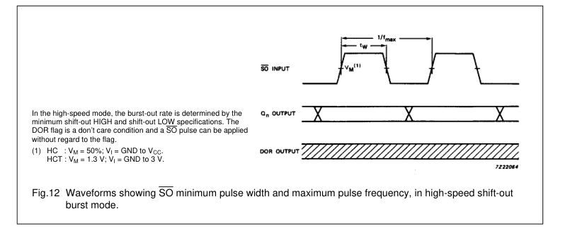
flag pulsing HIGH and a shift-out of data occurring. The SO control must capacity of the FIFO are not allowed be made LOW before additional data (see Figs 11 and 12). can be shifted-out (see Fig.10).
Expanded format
High-speed burst mode
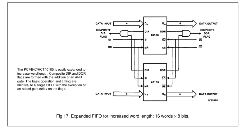
With the addition of a logic gate, the FIFO is easily expanded to increase
If it is assumed that the
word length (see Fig.17). The basic
shift-in/shift-out pulses are not
operation and timing are identical to a
applied until the respective status
single FIFO, with the exception of an
flags are valid, it follows that the shift-in/shift-out rates are determined additional gate delay on the flag by the status flags. However, without outputs. If during application, the
following occurs:
the status flags a high-speed burst mode can be implemented. In this
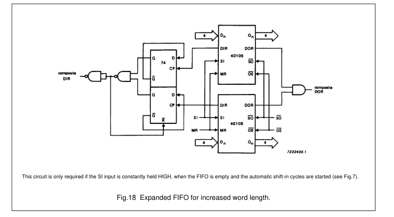
- SI is held HIGH when the FIFO is
mode, the burst-in/ burst-out rates are
empty, some additional logic is
determined by the pulse widths of the
required to produce a composite
shift-in/shift-out inputs and burst rates
DIR pulse (see Figs 7 and 18).
of 35 MHz can be obtained. Shift
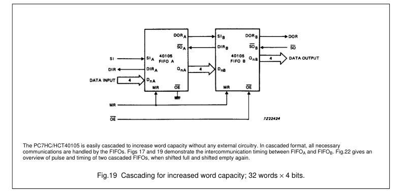
Due to the part-to-part spread of the ripple through time, the SI signals of FIFOA and FIFOB will not always coincide and the AND-gate will not produce a composite flag signal. The solution is given in Fig.18. The “40105” is easily cascaded to increase the word capacity and no external components are needed. In the cascaded configuration, all necessary communications and timing are performed by the FIFOs. The intercommunication speed is determined by the minimum flag pulse widths and the flag delays. The data rate of cascaded devices is typically 25 MHz. Word-capacity can be expanded to and beyond 32-words × 4-bits (see Fig.19).
Page 6
4-bit x 16-word FIFO register
74HC/HCT40105
Page 7
4-bit x 16-word FIFO register
74HC/HCT40105
DC CHARACTERISTICS FOR 74HC
For the DC characteristics see “74HC/HCT/HCU/HCMOS Logic Family Specifications”. Output capability: standard ICC category: MSI
AC CHARACTERISTICS FOR 74HC
GND = 0 V; tf = tf = 6 ns; CL = 50 pF
| SYMBOL | PARAMETER | T (°C) amb | UNIT | TEST CONDITIONS | |||||||
|---|---|---|---|---|---|---|---|---|---|---|---|
| 74HC | V CC (V) | WAVEFORMS | |||||||||
| +25 | −40 to +85 | −40 to +125 | |||||||||
| min. | typ. | max. | min. | max. | min. | max. | |||||
| t / t PHL PLH | propagation delay MR to DIR, DOR | 52 19 15 | 175 35 30 | 220 44 37 | 265 53 45 | ns | 2.0 4.5 6.0 | Fig.8 | |||
| t PHL | propagation delay SI to DIR | 52 19 15 | 210 42 36 | 265 53 45 | 315 63 54 | ns | 2.0 4.5 6.0 | Fig.6 | |||
| t PHL | propagation delay SO to DOR | 55 20 16 | 210 42 36 | 265 53 45 | 315 63 54 | ns | 2.0 4.5 6.0 | Fig.9 | |||
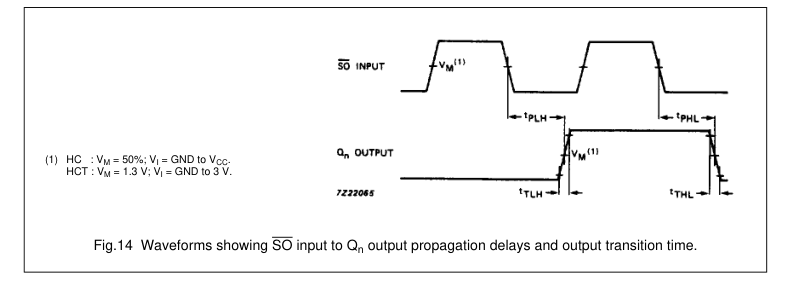
| t / t PHL PLH | propagation delay SO to Q n | 116 42 34 | 400 80 68 | 500 100 85 | 600 120 102 | ns | 2.0 4.5 6.0 | Fig.14 | |||
| t PLH | propagation delay/ ripple through delay SI to DOR | 564 205 165 | 2000 400 340 | 2500 500 425 | 3000 600 510 | ns | 2.0 4.5 6.0 | Fig.10 | |||
| t PLH | propagation delay/ bubble-up delay SO to DIR | 701 255 204 | 2500 500 425 | 3125 625 532 | 3750 750 638 | ns | 2.0 4.5 6.0 | Fig.7 | |||
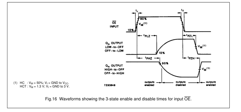
| t / t PZH PZL | 3-state output enable time OE to Q n | 41 15 12 | 150 30 26 | 190 38 33 | 225 45 38 | ns | 2.0 4.5 6.0 | Fig.16 | |||
| t / t PHZ PLZ | 3-state output disable time OE to Q n | 41 15 12 | 140 28 24 | 175 35 30 | 210 42 36 | ns | 2.0 4.5 6.0 | Fig.16 | |||
| t / t THL TLH | output transition time | 19 7 6 | 75 15 13 | 95 19 16 | 110 22 19 | ns | 2.0 4.5 6.0 | Fig.14 | |||
| t W | SI pulse width HIGH or LOW | 80 16 14 | 19 7 6 | 100 20 17 | 120 24 20 | ns | 2.0 4.5 6.0 | Fig.6 |
Page 8
4-bit x 16-word FIFO register
74HC/HCT40105
| SYMBOL | PARAMETER | T (°C) amb | UNIT | TEST CONDITIONS | |||||||
|---|---|---|---|---|---|---|---|---|---|---|---|
| 74HC | V CC (V) | WAVEFORMS | |||||||||
| +25 | −40 to +85 | −40 to +125 | |||||||||
| min. | typ. | max. | min. | max. | min. | max. | |||||
| t W | SO pulse width HIGH or LOW | 120 24 20 | 39 14 11 | 150 30 26 | 180 36 31 | ns | 2.0 4.5 6.0 | Fig.9 | |||
| t W | DIR pulse width HIGH | 12 6 5 | 58 21 17 | 180 36 31 | 10 5 4 | 225 45 38 | 10 5 4 | 270 54 46 | ns | 2.0 4.5 6.0 | Fig.7 |
| t W | DOR pulse width LOW | 12 6 5 | 55 20 16 | 170 34 29 | 10 5 4 | 215 43 37 | 10 5 4 | 255 51 43 | ns | 2.0 4.5 6.0 | Fig.9 |
| t W | MR pulse width HIGH | 80 16 14 | 22 8 6 | 100 20 17 | 120 24 20 | ns | 2.0 4.5 6.0 | Fig.8 | |||
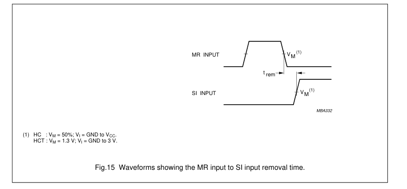
| t rem | removal time MR to SI | 50 10 9 | 14 5 4 | 65 13 11 | 75 15 13 | ns | 2.0 4.5 6.0 | Fig.15 | |||
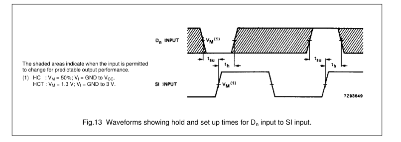
| t su | set-up time D to SI n | −5 −5 −5 | −39 −14 −11 | −5 −5 −5 | −5 −5 −5 | ns | 2.0 4.5 6.0 | Fig.13 | |||
| t h | hold time D to SI n | 125 25 21 | 44 16 13 | 155 31 26 | 190 38 32 | ns | 2.0 4.5 6.0 | Fig.13 | |||
| f max | maximum pulse frequency SI, SO using flags or burst mode | 3.6 18 21 | 10 30 36 | 2.8 14 16 | 2.4 12 14 | MHz | 2.0 4.5 6.0 | Fig.6, 9, 11 and 12 | |||
| f max | maximum pulse frequency SI, SO cascaded | 3.6 18 21 | 10 30 36 | 2.8 14 16 | 2.4 12 14 | MHz | 2.0 4.5 6.0 | Figs 6 and 9 |
Page 9
4-bit x 16-word FIFO register
74HC/HCT40105
DC CHARACTERISTICS FOR 74HCT
For the DC characteristics see “74HC/HCT/HCU/HCMOS Logic Family Specifications”. Output capability: standard ICC category: MSI
Note to HCT types The value of additional quiescent supply current (∆ICC) for a unit load of 1 is given in the family specifications. To determine ∆ICC per input, multiply this value by the unit load coefficient shown in the table below.
| INPUT | UNIT LOAD COEFFICIENT |
|---|---|
| OE SI D n MR SO | 0.75 0.40 0.30 1.50 0.40 |
AC CHARACTERISTICS FOR 74HCT
GND = 0 V; tf = tf = 6 ns; CL = 50 pF
| SYMBOL | PARAMETER | T (°C) amb | UNIT | TEST CONDITIONS | |||||||
|---|---|---|---|---|---|---|---|---|---|---|---|
| 74HCT | V CC (V) | WAVEFORMS | |||||||||
| +25 | −40 to +85 | −40 to +125 | |||||||||
| min. | typ. | max. | min. | max. | min. | max. | |||||
| t / t PHL PLH | propagation delay MR to DIR, DOR | 18 | 35 | 44 | 53 | ns | 4.5 | Fig.8 | |||
| t PHL | propagation delay SI to DIR | 21 | 42 | 53 | 63 | ns | 4.5 | Fig.6 | |||
| t PHL | propagation delay SO to DOR | 20 | 42 | 53 | 63 | ns | 4.5 | Fig.9 | |||
| t / t PHL PLH | propagation delay SO to Q n | 40 | 80 | 100 | 120 | ns | 4.5 | Fig.14 | |||
| t PLH | propagation delay/ ripple through delay SI to DOR | 188 | 400 | 500 | 600 | ns | 4.5 | Fig.10 | |||
| t PLH | propagation delay/ bubble-up delay SO to DIR | 244 | 500 | 625 | 750 | ns | 4.5 | Fig.7 | |||
| t / t PZH PZL | 3-state output enable time OE to Q n | 18 | 35 | 44 | 53 | ns | 4.5 | Fig.16 | |||
| t / t PHZ PLZ | 3-state output disable time OE to Q n | 15 | 30 | 38 | 45 | ns | 4.5 | Fig.16 | |||
| t / t THL TLH | output transition time | 7 | 15 | 19 | 22 | ns | 4.5 | Fig.14 |
Page 10
4-bit x 16-word FIFO register
74HC/HCT40105
| SYMBOL | PARAMETER | T (°C) amb | UNIT | TEST CONDITIONS | |||||||
|---|---|---|---|---|---|---|---|---|---|---|---|
| 74HCT | V CC (V) | WAVEFORMS | |||||||||
| +25 | −40 to +85 | −40 to +125 | |||||||||
| min. | typ. | max. | min. | max. | min. | max. | |||||
| t W | SI pulse width HIGH or LOW | 16 | 6 | 20 | 24 | ns | 4.5 | Fig.6 | |||
| t W | SO pulse width HIGH or LOW | 16 | 7 | 20 | 24 | ns | 4.5 | Fig.9 | |||
| t W | DIR pulse width HIGH or LOW | 6 | 20 | 34 | 5 | 43 | 5 | 51 | ns | 4.5 | Fig.7 |
| t W | DOR pulse width HIGH or LOW | 6 | 19 | 34 | 5 | 43 | 5 | 51 | ns | 4.5 | Fig.9 |
| t W | MR pulse width HIGH | 16 | 7 | 20 | 24 | ns | 4.5 | Fig.8 | |||
| t rem | removal time MR to SI | 15 | 7 | 19 | 22 | ns | 4.5 | Fig.15 | |||
| t su | set-up time D to SI n | −5 | −14 | −4 | −4 | ns | 4.5 | Fig.13 | |||
| t h | hold time D to SI n | 27 | 16 | 34 | 41 | ns | 4.5 | Fig.13 | |||
| f max | maximum pulse frequency SI, SO using flags or burst mode | 28 | 12 | 10 | MHz | 4.5 | Fig.6, 9, 11 and 12 | ||||
| f max | maximum pulse frequency SI, SO cascaded | 28 | 12 | 10 | MHz | 4.5 | Figs 6 and 9 |
Page 11

AC WAVEFORMS
Shifting in sequence FIFO empty to FIFO full
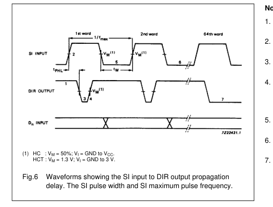
Notes to Fig.6 DIR initially HIGH; FIFO is prepared for valid data. SI set HIGH; data loaded into input stage. DIR drops LOW, input stage “busy”. DIR goes HIGH, status flag indicates FIFO prepared for additional data; data from first location “ripple through”. SI set LOW; necessary to complete shift-in process. Repeat process to load 2nd word through to 16th word into FIFO. DIR remains LOW: with attempt to shift into full FIFO, no data transfer occurs.
With FIFO full; SI held HIGH in anticipation of empty location
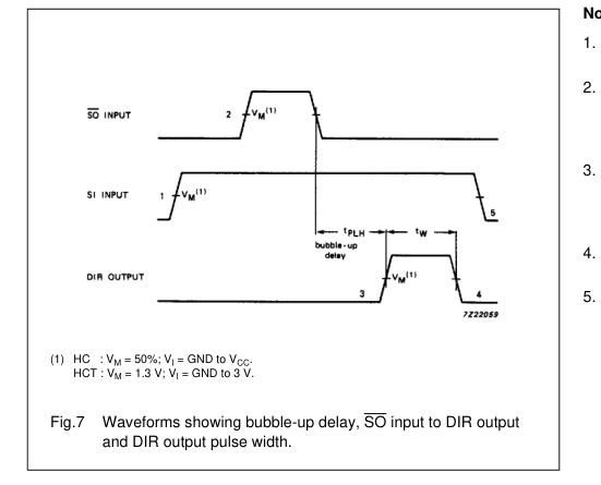
Notes to Fig.7 FIFO is initially, shift-in is held HIGH. SO pulse; data in the output stage is unloaded, “bubble-up process of empty locations begins”. DIR HIGH; when empty location reached input stage, flag indicates FIFO is prepared for data input. DIR returns to LOW; FIFO is full again. SI brought LOW; necessary to complete whidt-in process, DIR remains LOW, because FIFO is full.
Page 12

Master reset applied with FIFO full
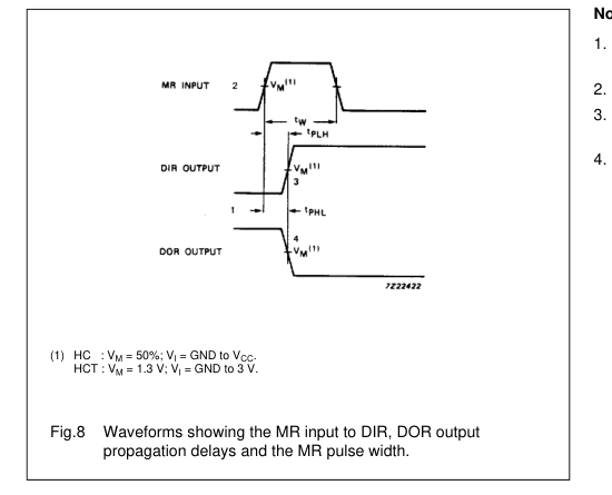
Notes to Fig.8 DIR LOW, output ready HIGH; assume FIFO is full. MR pulse HIGH; clears FIFO. DIR goes HIGH; flag indicates input prepared for valid data. DOR drops LOW; flag indicates FIFO empty.
Shifting out sequence; FIFO full to FIFO empty
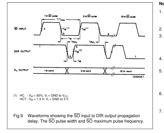
Notes to Fig.9 DOR HIGH; no data transfer in progress, valid data is present at output stage. SO set HIGH. SO is set LOW; data in the input stage is unloaded, and new data replaces it as empty location “bubbles-up” to input stage. DOR drops LOW; output stage “busy”. DOR goes HIGH; transfer process completed, valid data present at output after the specified propagation delay. Repeat process to unloaded the 3rd through to the 16th word from FIFO. DOR remains LOW; FIFO is empty.
Page 13

With FIFO empty; SO is held HIGH in anticipation
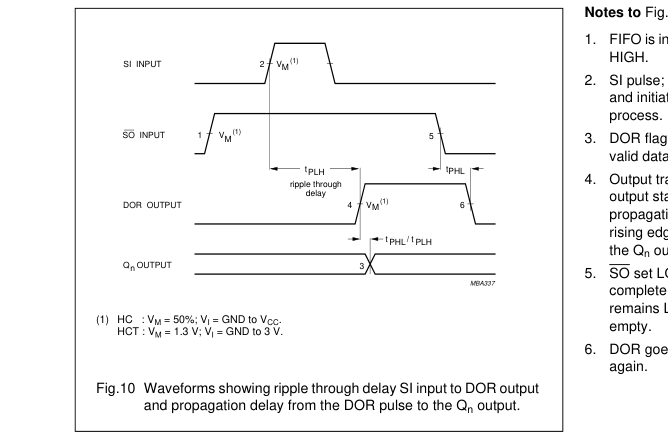
FIFO is initially empty, SO is held
SI pulse; loads data into FIFO and initiates ripple through
DOR flag signals the arrival of valid data at the output stage. Output transition; data arrives at output stage after the specified propagation delay between the rising edge of the DOR pulse to
SO set LOW; necessary to complete shift-out process. DOR remains LOW, because FIFO is
DOR goes LOW; FIFO is empty
Shift-in operation; high-speed burst mode
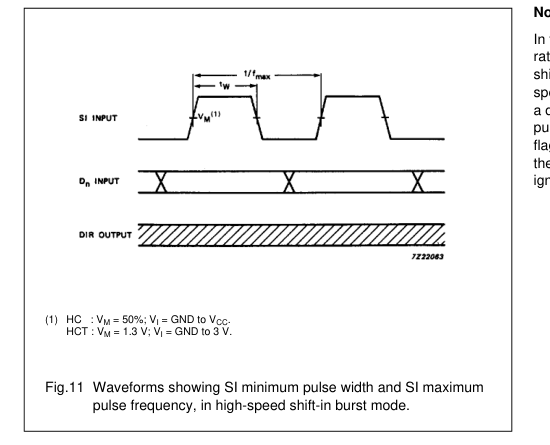
Note to Fig.11 In the high-speed mode, the burst-in rate is determined by the minimum shift-in HIGH and shift-in LOW specifications. The DIR status flag is a don’t care condition, and a shift-in pulse can be applied regardless of the flag. A SI pulse which would overflow the storage capacity of the FIFO is ignored.
Page 14
4-bit x 16-word FIFO register
74HC/HCT40105
Shift-out operation; high-speed burst mode
Page 15
4-bit x 16-word FIFO register
74HC/HCT40105
Page 16
4-bit x 16-word FIFO register
74HC/HCT40105
APPLICATION INFORMATION
Page 17
4-bit x 16-word FIFO register
74HC/HCT40105
Expanded format Fig.19 shows two cascaded FIFOs providing a capacity of 32 words × 4 bits Fig.20 shows the signals on the nodes of both FIFOs after the application of a SI pulse, when both FIFOs are initially empty. After a rippled through delay, date arrives at the output of FIFOA. Due to SOA being HIGH, a DOR pulse is generated. The requirements of SIB and DnB are satisfied by the DORA pulse width and the timing between the rising edge of DORA and QnA. After a second ripple through delay, data arrives at the output of FIFOB. Fig.21 shows the signals on the nodes of both FIFOs after the application of a SOR pulse, when both FIFOs are initially full. After a bubble-up delay a DIRR pulse is generated, which acts as a SOA pulse for FIFOA. One word is transferred
from the output of FIFOA to the input of FIFOB. The requirements of the SOA pulse for FIFOA is satisfied by the pulse width of DORB. After a second bubble-up delay an empty space arrives at DnA, at which time DIRA goes HIGH. Fig.22 shows the waveforms at all external nodes of both FIFOs during a complete shift-in and shift-out sequence.
Page 18

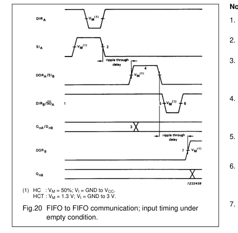
Notes to Fig.20 FIFOA and FIFOB initially empty, SOA held HIGH in anticipation of data. Load one word into FIFOA; SI pulse applied, results in DIR pulse. Data out A/data in B transition; valid data arrives at FIFOA output stage after a specified delay of the DOR flag, meeting data input set-up requirements of FIFOB. DORA and SIB pulse HIGH; (ripple through delay after SIA LOW) data is unloaded from FIFOA as a result of the data output ready pulse, data is shifted into FIFOB. DIRB and SOA go LOW; flag indicates input stage of FIFOB is busy, shift-out of FIFOA is complete. DIRB and SOA go HIGH automatically; the input stage of FIFOB is again able to receive data, SO is held HIGH in anticipation of
additional data. DORB goes HIGH; (ripple through delay after SIB LOW) valid data is present one propagation delay later at the FIFOB output stage.
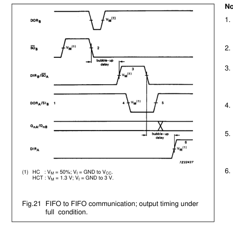
Notes to Fig.21 FIFOA and FIFOB initially empty, SIB held HIGH in anticipation of shifting in new data as empty location bubbles-up. Unload one word into FIFOB; SO pulse applied, results in DOR pulse. DIRB and SOA pulse HIGH; (bubble-up delay after SOB LOW) data is loaded into FIFOB as a result of the DIR pulse, data is shifted out of FIFOA. DORA and SIB go LOW; flag indicates the output stage of FIFOA is busy, shift-in to FIFOR is complete. DORA and SIB go HIGH; flag indicates valid data is again available at FIFOA output stage, SIB is held HIGH, awaiting bubble-up of empty location. DIRA goes HIGH; (bubble-up delay after SOA LOW) an empty location is present at
input stage of FIFOA.
Page 19

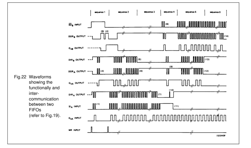
Note to Fig.22 Sequence 1 (Both FIFOs empty, starting shift-in process): After a MR pulse has been applied FIFOA and FIFOB are empty. The DOR flags of FIFOA and FIFOB go LOW due to no valid data being present at the outputs. The DIR flags are set HIGH due to the FIFOs being ready to accept data. SOB is held HIGH and two SIA pulses are applied (1). These pulses allow two data words to ripple through to the output stage of FIFOA and to the input stage of FIFOB (2). When data arrives at the output of FIFOB, a DORB pulse is generated (3). When SOB goes LOW, the first bit is shifted out and a second bit ripples through to the output after which DORB goes HIGH (4).
Sequence 2 (FIFOB runs full): After the MR pulse, a series of 16 SI pulses are applied. When 16 words are shifted in, DIRB remains LOW due to FIFOB being full (5). DORA goes LOW due to FIFOA being empty. Sequence 3 (FIFOA runs full): When 17 words are shifted in, DORA remains HIGH due to valid data remaining at the output of FIFOA. QnA remains HIGH, being the polarity of the 17th data word (6). After the 32th SI pulse, DIR remains LOW and both FIFOs are full (7). Additional pulses have no effect.
Sequence 4 (Both FIFOs full, starting shift-out process): SIA is held HIGH and two SOB pulses are applied (8). These pulses shift out two words and thus allow empty locations to bubble-up to the input stage of FIFOB, and proceed to FIFOA (9). When the first empty location arrives at the input of FIFOA, a DIRA pulse is generated (10) and a new word is shifted into FIFOA. SIA is made LOW and now the second empty location reaches the input stage of FIFOA, after which DIRA remains HIGH (11). Sequence 5 (FIFOA runs empty): At the start of sequence 5 FIFOA contains 15 valid words due to two words being shifted out and one word being shifted in sequence 4. An additional series of SOB pulses
are applied. After 15 SOB pulses, all words from FIFOA are shifted into FIFOB. DORA remains LOW (12). Sequence 6 (FIFOB runs empty): After the next SOB pulse, DIRB remains HIGH due to the input stage of FIFOB being empty (13). After another 15 SOB pulses, DORB remains LOW due to both FIFOs being empty (14). Additional SOB pulses have no effect. The last word remains available at the output Qn.
Page 20

PACKAGE OUTLINES
DIP16: plastic dual in-line package; 16 leads (300 mil); long body
SOT38-1
ME
D
A2 A
A1
L
c
e
w M
Z
b1
(e ) 1
b
MH
9
16
pin 1 index
E
1
8
0
5 10 mm
scale
DIMENSIONS (inch dimensions are derived from the original mm dimensions)
| UNIT | A max. | A 1 min. | A 2 max. | b | b1 | c | D(1) | E(1) | e | e1 | L | ME | MH | w | Z(1) max. |
|---|---|---|---|---|---|---|---|---|---|---|---|---|---|---|---|
| mm | 4.7 | 0.51 | 3.7 | 1.40 1.14 | 0.53 0.38 | 0.32 0.23 | 21.8 21.4 | 6.48 6.20 | 2.54 | 7.62 | 3.9 3.4 | 8.25 7.80 | 9.5 8.3 | 0.254 | 2.2 |
| inches | 0.19 | 0.020 | 0.15 | 0.055 0.045 | 0.021 0.015 | 0.013 0.009 | 0.86 0.84 | 0.26 0.24 | 0.10 | 0.30 | 0.15 0.13 | 0.32 0.31 | 0.37 0.33 | 0.01 | 0.087 |
Note 1. Plastic or metal protrusions of 0.25 mm maximum per side are not included.
REFERENCES
OUTLINE
EUROPEAN
ISSUE DATE
VERSION
PROJECTION
IEC
JEDEC
EIAJ
92-10-02
SOT38-1
050G09
MO-001AE
95-01-19
Page 21
4-bit x 16-word FIFO register
74HC/HCT40105
SO16: plastic small outline package; 16 leads; body width 3.9 mm
SOT109-1
D
E
A X
c
y
HE
v M A
Z
16
9
Q
A2
A (A ) 3
A1
pin 1 index
θ Lp L
1
8
e
detail X
w M bp
0 2.5 5 mm
scale
DIMENSIONS (inch dimensions are derived from the original mm dimensions)
| UNIT | A max. | A1 | A2 | A3 | bp | c | D(1) | E(1) | e | HE | L | Lp | Q | v | w | y | Z(1) | θ |
|---|---|---|---|---|---|---|---|---|---|---|---|---|---|---|---|---|---|---|
| mm | 0 1.75 0 | .25 .10 | 1.45 1.25 | 0.25 | 0.49 0.36 | 0.25 0.19 | 10.0 9.8 | 4.0 3.8 | 1.27 | 6.2 5.8 | 1.05 | 1.0 0.4 | 0.7 0.6 | 0.25 | 0.25 | 0.1 | 0.7 0.3 | 8o 0o |
| inches | 0 0.069 0 | .010 .004 | 0.057 0.049 | 0.01 | 0.019 0.014 | 0.0100 0.0075 | 0.39 0.38 | 0.16 0.15 | 0.050 | 0.244 0.228 | 0.041 | 0.039 0.016 | 0.028 0.020 | 0.01 | 0.01 | 0.004 | 0.028 0.012 |
Note 1. Plastic or metal protrusions of 0.15 mm maximum per side are not included.
REFERENCES
OUTLINE
EUROPEAN
ISSUE DATE
VERSION
PROJECTION
IEC
JEDEC
EIAJ
95-01-23
076E07S
MS-012AC
SOT109-1
97-05-22
Page 22
4-bit x 16-word FIFO register
74HC/HCT40105
SSOP16: plastic shrink small outline package; 16 leads; body width 5.3 mm
SOT338-1
D
E
A X
c
y
HE
v M A
Z
9
16
Q
A2
A (A )
A1
3
pin 1 index
θ Lp L
8
1
detail X
w M bp
e
0 2.5 5 mm
scale
DIMENSIONS (mm are the original dimensions)
| UNIT | A max. | A 1 | A 2 | A 3 | bp | c | D(1) | E (1) | e | H E | L | Lp | Q | v | w | y | Z(1) | θ |
|---|---|---|---|---|---|---|---|---|---|---|---|---|---|---|---|---|---|---|
| mm | 2.0 | 0.21 0.05 | 1.80 1.65 | 0.25 | 0.38 0.25 | 0.20 0.09 | 6.4 6.0 | 5.4 5.2 | 0.65 | 7.9 7.6 | 1.25 | 1.03 0.63 | 0.9 0.7 | 0.2 | 0.13 | 0.1 | 1.00 0.55 | 8o 0o |
Note 1. Plastic or metal protrusions of 0.25 mm maximum per side are not included.
REFERENCES
OUTLINE
EUROPEAN
ISSUE DATE
VERSION
PROJECTION
IEC
JEDEC
EIAJ
94-01-14
MO-150AC
SOT338-1
95-02-04
Page 23
4-bit x 16-word FIFO register
74HC/HCT40105
TSSOP16: plastic thin shrink small outline package; 16 leads; body width 4.4 mm
SOT403-1
E
A
D
X
c
y
HE
v M A
Z
9
16
Q (A )
A2
3 A
A1
pin 1 index
θ
Lp L
1
8
detail X
w M bp
e
0 2.5 5 mm
scale
DIMENSIONS (mm are the original dimensions)
| UNIT | A max. | A1 | A2 | A3 | bp | c | D (1) | E (2) | e | HE | L | Lp | Q | v | w | y | Z(1) | θ |
|---|---|---|---|---|---|---|---|---|---|---|---|---|---|---|---|---|---|---|
| mm | 1.10 | 0.15 0.05 | 0.95 0.80 | 0.25 | 0.30 0.19 | 0.2 0.1 | 5.1 4.9 | 4.5 4.3 | 0.65 | 6.6 6.2 | 1.0 | 0.75 0.50 | 0.4 0.3 | 0.2 | 0.13 | 0.1 | 0.40 0.06 | 8o 0o |
Notes 1. Plastic or metal protrusions of 0.15 mm maximum per side are not included. 2. Plastic interlead protrusions of 0.25 mm maximum per side are not included.
REFERENCES
OUTLINE
EUROPEAN
ISSUE DATE
VERSION
PROJECTION
IEC
JEDEC
EIAJ
94-07-12
SOT403-1
MO-153
95-04-04
Page 24

SOLDERING
Introduction There is no soldering method that is ideal for all IC packages. Wave soldering is often preferred when through-hole and surface mounted components are mixed on one printed-circuit board. However, wave soldering is not always suitable for surface mounted ICs, or for printed-circuits with high population densities. In these situations reflow soldering is often used. This text gives a very brief insight to a complex technology. A more in-depth account of soldering ICs can be found in our “IC Package Databook” (order code 9398 652 90011).
DIP SOLDERING BY DIPPING OR BY WAVE The maximum permissible temperature of the solder is 260 °C; solder at this temperature must not be in contact with the joint for more than 5 seconds. The total contact time of successive solder waves must not exceed 5 seconds. The device may be mounted up to the seating plane, but the temperature of the plastic body must not exceed the specified maximum storage temperature (Tstg max). If the printed-circuit board has been pre-heated, forced cooling may be necessary immediately after soldering to keep the temperature within the permissible limit.
REPAIRING SOLDERED JOINTS Apply a low voltage soldering iron (less than 24 V) to the lead(s) of the package, below the seating plane or not more than 2 mm above it. If the temperature of the soldering iron bit is less than 300 °C it may remain in contact for up to 10 seconds. If the bit temperature is between 300 and 400 °C, contact may be up to 5 seconds.
SO, SSOP and TSSOP REFLOW SOLDERING Reflow soldering techniques are suitable for all SO, SSOP and TSSOP packages. Reflow soldering requires solder paste (a suspension of fine solder particles, flux and binding agent) to be applied to the printed-circuit board by screen printing, stencilling or pressure-syringe dispensing before package placement. Several techniques exist for reflowing; for example, thermal conduction by heated belt. Dwell times vary between 50 and 300 seconds depending on heating method.
Typical reflow temperatures range from 215 to 250 °C. Preheating is necessary to dry the paste and evaporate the binding agent. Preheating duration: 45 minutes at 45 °C.
WAVE SOLDERING Wave soldering can be used for all SO packages. Wave soldering is not recommended for SSOP and TSSOP packages, because of the likelihood of solder bridging due to closely-spaced leads and the possibility of incomplete solder penetration in multi-lead devices. If wave soldering is used - and cannot be avoided for SSOP and TSSOP packages - the following conditions must be observed:
- A double-wave (a turbulent wave with high upward pressure followed by a smooth laminar wave) soldering technique should be used.
- The longitudinal axis of the package footprint must be parallel to the solder flow and must incorporate solder thieves at the downstream end.
Even with these conditions:
- Only consider wave soldering SSOP packages that have a body width of 4.4 mm, that is SSOP16 (SOT369-1) or SSOP20 (SOT266-1).
- Do not consider wave soldering TSSOP packages with 48 leads or more, that is TSSOP48 (SOT362-1) and TSSOP56 (SOT364-1).
During placement and before soldering, the package must be fixed with a droplet of adhesive. The adhesive can be applied by screen printing, pin transfer or syringe dispensing. The package can be soldered after the adhesive is cured. Maximum permissible solder temperature is 260 °C, and maximum duration of package immersion in solder is 10 seconds, if cooled to less than 150 °C within 6 seconds. Typical dwell time is 4 seconds at 250 °C. A mildly-activated flux will eliminate the need for removal of corrosive residues in most applications.
REPAIRING SOLDERED JOINTS Fix the component by first soldering two diagonallyopposite end leads. Use only a low voltage soldering iron (less than 24 V) applied to the flat part of the lead. Contact time must be limited to 10 seconds at up to 300 °C. When using a dedicated tool, all other leads can be soldered in one operation within 2 to 5 seconds between 270 and 320 °C.
Page 25
4-bit x 16-word FIFO register
74HC/HCT40105
DEFINITIONS
| Column 1 | Column 2 |
|---|---|
| Data sheet status | |
| Objective specification | This data sheet contains target or goal specifications for product development. |
| Preliminary specification | This data sheet contains preliminary data; supplementary data may be published later. |
| Product specification | This data sheet contains final product specifications. |
| Limiting values | |
| Limiting values given are in accordance with the Absolute Maximum Rating System (IEC 134). Stress above one or more of the limiting values may cause permanent damage to the device. These are stress ratings only and operation of the device at these or at any other conditions above those given in the Characteristics sections of the specification is not implied. Exposure to limiting values for extended periods may affect device reliability. | |
| Application information | |
| Where application information is given, it is advisory and does not form part of the specification. |
LIFE SUPPORT APPLICATIONS
These products are not designed for use in life support appliances, devices, or systems where malfunction of these products can reasonably be expected to result in personal injury. Philips customers using or selling these products for use in such applications do so at their own risk and agree to fully indemnify Philips for any damages resulting from such improper use or sale.