74HC40102 PHILIPS
Document overview
- PDF pages: 11
Technical content
Page 1
Page 2
FEATURES
- Cascadable
- Synchronous or asynchronous preset
- Output capability: standard
- ICC category: MSI
GENERAL DESCRIPTION
The 74HC/HCT40102 are high-speed Si-gate CMOS devices and are pin compatible with the “40102” of the “4000B” series. They are specified in compliance with JEDEC standard no. 7A. The 74HC/HCT40102 consist each of an 8-bit synchronous down counter with a single output which is active when the internal count is zero. The “40102” is configured as two cascaded 4-bit BCD counters and has control inputs for enabling or disabling the clock (CP), for clearing the counter to its maximum count, and for presetting the counter either synchronously or asynchronously. All control inputs and the terminal count output (TC) are active-LOW logic. In normal operation, the counter is decremented by one
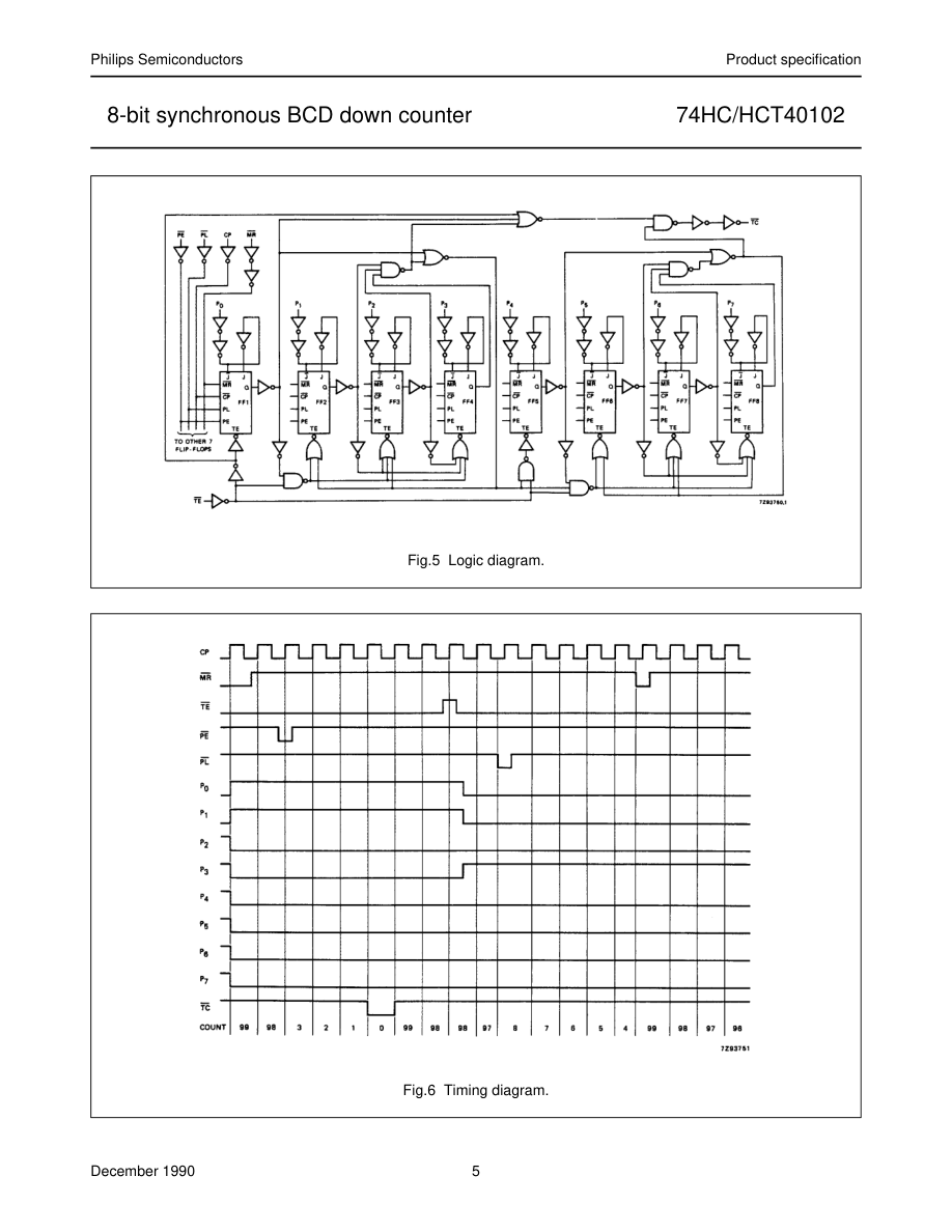
count on each positive-going transition of the clock (CP). Counting is inhibited when the terminal enable input (TE) is HIGH. The terminal count output (TC) goes LOW when the count reaches zero if TE is LOW, and remains LOW for one full clock period.
QUICK REFERENCE DATA
GND = 0 V; Tamb = 25 °C; tr = tf = 6 ns
When the synchronous preset enable input (PE) is LOW, data at the jam input (P0 to P7) is clocked into the counter on the next positive-going clock transition regardless of the state of TE. When the asynchronous preset enable input (PL) is LOW, data at the jam input (P0 to P7) is asynchronously forced into the counter regardless of the state of PE, TE, or CP. The jam inputs (P0 to P7) represent two 4-bit BCD words. When the master reset input (MR) is LOW, the counter is asynchronously cleared to its maximum count (decimal 99) regardless of the state of any other input. The precedence relationship between control inputs is indicated in the function table. If all control inputs except TE are HIGH at the time of zero
count, the counters will jump to the maximum count, giving a counting sequence of 100 clock pulses long. The “40102” may be cascaded using the TE input and the TC output, in either a synchronous or ripple mode.
APPLICATIONS
- Divide-by-n counters
- Programmable timers
- Interrupt timers
- Cycle/program counters
| SYMBOL | PARAMETER | CONDITIONS | TYPICAL | UNIT | |
|---|---|---|---|---|---|
| HC | HCT | ||||
| t / t PHL PLH | propagation delay CP to TC | C = 15 pF; V = 5 V L CC | 30 | 31 | ns |
| f max | maximum clock frequency | 30 | 30 | MHz | |
| C I | input capacitance | 3.5 | 3.5 | pF | |
| C PD | power dissipation capacitance per package | notes 1 and 2 | 20 | 25 | pF |
Notes 1. CPD is used to determine the dynamic power dissipation (PD in µW): PD = CPD × VCC2 × fi + ∑ (CL × VCC2 × fo) where: fi = input frequency in MHz fo = output frequency in MHz ∑ (CL × VCC2 × fo) = sum of outputs CL = output load capacitance in pF VCC = supply voltage in V
Page 3
- For HC the condition is VI = GND to VCC For HCT the condition is VI = GND to VCC − 1.5 V
ORDERING INFORMATION
See “74HC/HCT/HCU/HCMOS Logic Package Information”.
PIN DESCRIPTION
| PIN NO. | SYMBOL | NAME AND FUNCTION |
|---|---|---|
| 1 2 3 4, 5, 6, 7, 10, 11, 12, 13 8 9 14 15 16 | CP MR TE P to P 0 7 GND PL TC PE V CC | clock input (LOW-to-HIGH, edge-triggered) asynchronous master reset input (active LOW) terminal enable input jam inputs ground (0 V) asynchronous preset enable input (active LOW) terminal count output (active LOW) synchronous preset enable input (active LOW) positive supply voltage |
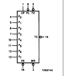
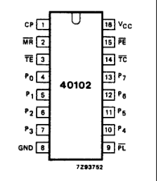
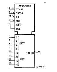
Fig.2 Logic symbol.
Fig.1 Pin configuration.
Fig.3 IEC logic symbol.
Page 4
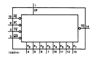
Fig.4 Functional diagram.
FUNCTION TABLE
| Column 1 | Column 2 | Column 3 | Column 4 | Column 5 | Column 6 |
|---|---|---|---|---|---|
| CONTROL INPUTS | PRESET MODE | ACTION | |||
| MR | PL | PE | TE | ||
| H | H | H | H | synchronous | inhibit counter |
| H | H | H | L | count down | |
| H | H | L | X | preset on next LOW-to HIGH clock transition | |
| H | L | X | X | asynchronous | preset asynchronously |
| L | X | X | X | clear to maximum count |
Notes 1. Clock connected to CP. 2. Synchronous operation: changes occur on the LOW-to-HIGH CP transition. 3. Jam inputs: MSD = P7, LSD = P0.
H = HIGH voltage level L = LOW voltage level X = don’t care
Page 5
Page 6
DC CHARACTERISTICS FOR 74HC
For the DC characteristics see “74HC/HCT/HCU/HCMOS Logic Family Specifications”. Output capability: standard ICC category: MSI
AC CHARACTERISTICS FOR 74HC
GND = 0 V; tr = tf = 6 ns; CL = 50 pF
| SYMBOL | PARAMETER | T (°C) amb | UNIT | TEST CONDITIONS | |||||||
|---|---|---|---|---|---|---|---|---|---|---|---|
| 74HC | V CC (V) | WAVEFORMS | |||||||||
| +25 | −40 to +85 | −40 to +125 | |||||||||
| min. | typ. | max. | min. | max. | min. | max. | |||||
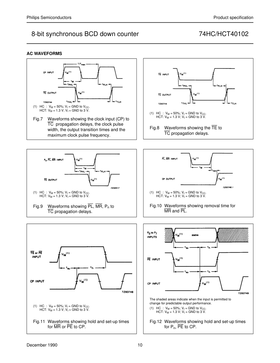
| t / t PHL PLH | propagation delay CP to TC | 96 35 28 | 300 60 51 | 375 75 64 | 450 90 77 | ns | 2.0 4.5 6.0 | Fig.8 | |||
| t / t PHL PLH | propagation delay TE to TC | 50 18 14 | 200 40 34 | 250 50 43 | 300 60 51 | ns | 2.0 4.5 6.0 | Fig.8 | |||
| t / t PHL PLH | propagation delay P , PL to TC n | 110 40 32 | 240 68 58 | 425 85 72 | 510 102 87 | ns | 2.0 4.5 6.0 | Fig.8 | |||
| t PLH | propagation delay MR to TC | 83 30 24 | 275 55 47 | 345 69 59 | 415 83 71 | ns | 2.0 4.5 6.0 | Fig.8 | |||
| t / t THL TLH | output transition time | 9 7 6 | 75 15 13 | 95 19 16 | 110 22 19 | ns | 2.0 4.5 6.0 | Figs 8 and 8 | |||
| t W | clock pulse width HIGH or LOW | 165 33 28 | 22 8 6 | 205 41 35 | 250 50 43 | ns | 2.0 4.5 6.0 | Fig.8 | |||
| t W | master reset pulse width LOW | 150 30 26 | 30 11 9 | 190 38 33 | 225 45 38 | ns | 2.0 4.5 6.0 | Fig.8 | |||
| t W | preset enable pulse width PL; LOW | 125 25 21 | 39 14 11 | 155 31 26 | 190 38 32 | ns | 2.0 4.5 6.0 | Fig.8 | |||
| t rem | removal time PL; MR to CP | 50 10 9 | 8 3 2 | 65 13 11 | 75 15 13 | ns | 2.0 4.5 6.0 | Fig.8 | |||
| t su | set-up time PE to CP | 100 20 17 | 36 13 10 | 125 25 21 | 150 30 26 | ns | 2.0 4.5 6.0 | Fig.8 | |||
| t su | set-up time TE to CP | 175 35 30 | 50 18 14 | 220 44 37 | 265 53 45 | ns | 2.0 4.5 6.0 | Fig.8 |
Page 7
| SYMBOL | PARAMETER | T (°C) amb | UNIT | TEST CONDITIONS | |||||||
|---|---|---|---|---|---|---|---|---|---|---|---|
| 74HC | V CC (V) | WAVEFORMS | |||||||||
| +25 | −40 to +85 | −40 to +125 | |||||||||
| min. | typ. | max. | min. | max. | min. | max. | |||||
| t su | set-up time P to CP n | 100 20 17 | 33 12 10 | 125 25 21 | 150 30 26 | ns | 2.0 4.5 6.0 | Fig.8 | |||
| t h | hold time PE to CP | 2 2 2 | −8 −3 −2 | 2 2 2 | 2 2 2 | ns | 2.0 4.5 6.0 | Fig.8 | |||
| t h | hold time TE to CP | 0 0 0 | −41 −15 −12 | 0 0 0 | 0 0 0 | ns | 2.0 4.5 6.0 | Fig.8 | |||
| t h | hold time P to CP n | 2 2 2 | −5 −5 −5 | 2 2 2 | 2 2 2 | ns | 2.0 4.5 6.0 | Fig.8 | |||
| f max | maximum clock pulse frequency | 3 15 18 | 8.9 27 32 | 2 12 14 | 2 10 12 | MHz | 2.0 4.5 6.0 | Fig.8 |
Page 8
DC CHARACTERISTICS FOR 74HCT
For the DC characteristics see “74HC/HCT/HCU/HCMOS Logic Family Specifications”. Output capability: standard ICC category: MSI
Note to HCT types The value of additional quiescent supply current (∆ICC) for a unit load of 1 is given in the family specifications. To determine ∆ICC per input, multiply this value by the unit load coefficient shown in the table below.
| INPUT | UNIT LOAD COEFFICIENT |
|---|---|
| CP, PE MR TE P n PL | 1.50 1.00 0.80 0.25 0.35 |
Page 9
AC CHARACTERISTICS FOR 74HCT
GND = 0 V; tr = tf = 6 ns; CL = 50 pF
| SYMBOL | PARAMETER | T (°C) amb | UNIT | TEST CONDITIONS | |||||||
|---|---|---|---|---|---|---|---|---|---|---|---|
| 74HCT | V CC (V) | WAVEFORMS | |||||||||
| +25 | −40 to +85 | −40 to +125 | |||||||||
| min. | typ. | max. | min. | max. | min. | max. | |||||
| t / t PHL PLH | propagation delay P ; CP to TC n | 38 | 63 | 79 | 95 | ns | 4.5 | Figs 8 and 8 | |||
| t / t PHL PLH | propagation delay TE to TC | 25 | 50 | 63 | 75 | ns | 4.5 | Fig.8 | |||
| t / t PHL PLH | propagation delay PL to TC | 49 | 83 | 104 | 125 | ns | 4.5 | Fig.8 | |||
| t PLH | propagation delay MR to TC | 31 | 55 | 69 | 83 | ns | 4.5 | Fig.8 | |||
| t / t THL TLH | output transition time | 7 | 15 | 19 | 22 | ns | 4.5 | Figs 8 and 8 | |||
| t W | clock pulse width HIGH or LOW | 33 | 11 | 41 | 50 | ns | 4.5 | Fig.8 | |||
| t W | master reset pulse width LOW | 30 | 16 | 38 | 45 | ns | 4.5 | Fig.8 | |||
| t W | preset enable pulse width PL; LOW | 43 | 25 | 54 | 65 | ns | 4.5 | Fig.8 | |||
| t rem | removal time PL; MR to CP | 10 | 1 | 13 | 15 | ns | 4.5 | Fig.8 | |||
| t su | set-up time PE to CP | 20 | 10 | 25 | 30 | ns | 4.5 | Fig.8 | |||
| t su | set-up time TE to CP | 40 | 20 | 50 | 60 | ns | 4.5 | Fig.8 | |||
| t su | set-up time P to CP n | 20 | 12 | 25 | 30 | ns | 4.5 | Fig.8 | |||
| t h | hold time PE to CP | 0 | −4 | 0 | 0 | ns | 4.5 | Fig.8 | |||
| t h | hold time TE to CP | 0 | −15 | 0 | 0 | ns | 4.5 | Fig.8 | |||
| t h | hold time P to CP n | 0 | −6 | 0 | 0 | ns | 4.5 | Fig.8 | |||
| f max | maximum clock pulse frequency | 15 | 27 | 12 | 10 | MHz | 4.5 | Fig.8 |
Page 10
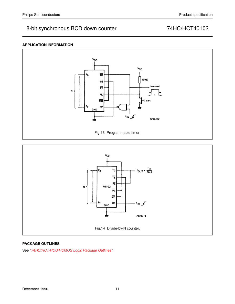
Page 11