


 Download PDF
74HC2G66 NXP
Document overview
- PDF pages: 21
Technical content
Page 1
1. General description
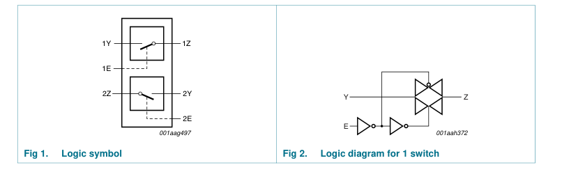
74HC2G66 and 74HCT2G66 are high-speed Si-gate CMOS devices. They are dual single-pole single-throw analog switches. Each switch has two input/output pins (nY and nZ) and an active HIGH enable input pin (nE). When pin nE is LOW, the analog switch is turned off.
2. Features and benefits
Wide supply voltage range from 2.0 V to 10.0 V for 74HC2G66 Very low ON resistance: 41 Ω (typ.) at VCC = 4.5 V 30 Ω (typ.) at VCC = 6.0 V 21 Ω (typ.) at VCC = 9.0 V High noise immunity Low power dissipation 25 mA continuous switch current Multiple package options ESD protection: HBM JESD22-A114F exceeds 2000 V MM JESD22-A115-A exceeds 200 V Specified from −40 °C to +85 °C and −40 °C to +125 °C
3. Ordering information
Table 1. Ordering information
| Type number | Package | |||
|---|---|---|---|---|
| Temperature range | Name | Description | Version |
74HC2G66DP
−40 °C to +125 °C
TSSOP8
74HCT2G66DP 74HC2G66DC
−40 °C to +125 °C
VSSOP8
74HCT2G66DC 74HC2G66GD
−40 °C to +125 °C
XSON8U
74HCT2G66GD
plastic thin shrink small outline package; 8
SOT505-2
leads; body width 3 mm; lead length 0.5 mm
plastic very thin shrink small outline package; 8 SOT765-1 leads; body width 2.3 mm
plastic extremely thin small outline package; no SOT996-2 leads; 8 terminals; UTLP based; body 3 × 2 × 0.5 mm

Page 2
4. Marking
Table 2. Marking codes Type number
Marking
74HC2G66DP
H66
74HCT2G66DP
T66
74HC2G66DC
H66
74HCT2G66DC
T66
74HC2G66GD
H66
74HCT2G66GD
T66
5. Functional diagram
6. Pinning information
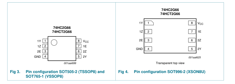
6.1 Pinning
2 of 21
Page 3
6.2 Pin description
Table 3. Pin description Symbol
Pin
1Y, 2Y
1, 5
1Z, 2Z
2, 6
GND
4
1E, 2E
7, 3 8
VCC
7. Functional description
Table 4. Function table[1] Input nE L H
[1] H = HIGH voltage level; L = LOW voltage level.
8. Limiting values
Table 5. Limiting values
Description
independent input or output independent input or output ground (0 V) enable input (active HIGH) supply voltage
Switch OFF ON
In accordance with the Absolute Maximum Rating System (IEC 60134). Voltages are referenced to GND (ground = 0 V). Symbol
Parameter
Conditions
Min Max Unit
supply voltage
−0.5 +11.0 V
VCC
[1] -
VI < −0.5 V or VI > VCC + 0.5 V
input clamping current
±20 mA
IIK
[1] -
VI < −0.5 V or VI > VCC + 0.5 V
switch clamping current
±20 mA
ISK
VSW > −0.5 V or VSW < VCC + 0.5 V
switch current
- ±20 mA
ISW
supply current
- 30 mA
ICC
ground current
−30 - mA
IGND
storage temperature
−65 +150 °C
Tstg
Tamb = −40 °C to +125 °C
total power dissipation
Ptot
[2] -
300 mW
per package
[2] -
100 mW
per switch
[1] The input and output voltage ratings may be exceeded if the input and output current ratings are observed. [2] For TSSOP8 packages above 55 °C the value of Ptot derates linearly with 2.5 mW/K. For VSSOP8 packages above 110 °C the value of Ptot derates linearly with 8.0 mW/K. For XSON8U package: above 118 °C the value of Ptot derates linearly with 7.8 mW/K.
3 of 21
Page 4
9. Recommended operating conditions
Table 6. Recommended operating conditions Voltages are referenced to GND (ground = 0 V).[1]
| Symbol | Parameter | Conditions | 74HC2G66 | 74HCT2G66 | Unit | ||||
|---|---|---|---|---|---|---|---|---|---|
| Min | Typ | Max | Min | Typ | Max |
supply voltage
2.0 5.0 10.0 4.5 5.0 5.5 V
VCC input voltage
0 - VCC 0 - VCC V
VI output voltage
0 - VCC 0 - VCC V
VO switch voltage
0 - VCC 0 - VCC V
VSW ambient temperature
−40 +25 +125 −40 +25 +125 °C
Tamb
VCC = 2.0 V
- - 625 - - - ns/V
Δt/ΔV input transition rise and fall rate
VCC = 4.5 V
- 1.67 139 - 1.67 139 ns/V
VCC = 6.0 V
- - 83 - - - ns/V
VCC = 10.0 V
- - 35 - - - ns/V
[1] To avoid drawing VCC current out of pin nZ, when switch current flows in pin nY, the voltage drop across the bidirectional switch must not exceed 0.4 V. If the switch current flows into pin nZ, no VCC current will flow out of terminal nY. In this case there is no limit for the voltage drop across the switch, but the voltage at pins nY and nZ may not exceed VCC or GND.
10. Static characteristics
Table 7. Static characteristics Voltages are referenced to GND (ground = 0 V).
| Symbol Parameter Conditions | −40 °C to +85 °C | −40 °C to +125 °C | Unit | |||
|---|---|---|---|---|---|---|
| Min | Typ[1] | Max | Min | Max |
74HC2G66 HIGH-level
VCC = 2.0 V
1.5 1.2 - 1.5 - V
VIH input voltage
VCC = 4.5 V
3.15 2.4
- 3.15 - V
VCC = 6.0 V
4.2 3.2 - 4.2 - V
VCC = 9.0 V
6.3 4.7 - 6.3 - V
LOW-level
VCC = 2.0 V
- 0.8 0.5 - 0.5 V
VIL input voltage
VCC = 4.5 V
- 2.1 1.35
- 1.35 V
VCC = 6.0 V
- 2.8 1.8 - 1.8 V
VCC = 9.0 V
- 4.3 2.7 - 2.7 V
input leakage current
nE; VI = VCC or GND
II
VCC = 6.0 V
- - ±0.1 - ±0.1 μA
VCC = 9.0 V
- - ±0.2 - ±0.2 μA
OFF-state
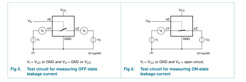
nY or nZ; VCC = 9.0 V; see Figure 5
- 0.1 1.0 - 1.0 μA
IS(OFF) leakage current ON-state
nY or nZ; VCC = 9.0 V; see Figure 6
- 0.1 1.0 - 1.0 μA
IS(ON) leakage current supply current
nE, nY and nZ = VCC or GND
ICC
VCC = 6.0 V
- - 10 - 20 μA
VCC = 9.0 V
- - 20 - 40 μA
4 of 21
Page 5
Table 7. Static characteristics …continued Voltages are referenced to GND (ground = 0 V).
| Symbol Parameter Conditions | −40 °C to +85 °C | −40 °C to +125 °C | Unit | |||
|---|---|---|---|---|---|---|
| Min | Typ[1] | Max | Min | Max |
CI input capacitance
- 3.5 - - - pF
power dissipation
- 9 - - - pF
CPD capacitance ON-state capacitance
- 8 - - - pF
CS(ON)
74HCT2G66
HIGH-level
VCC = 4.5 V to 5.5 V
2.0 1.6 - 2.0 - V
VIH input voltage LOW-level
VCC = 4.5 V to 5.5 V
- 1.2 0.8 - 0.8 V
VIL input voltage II input leakage current
nE; VI = VCC or GND; VCC = 5.5 V
- - ±1.0 - ±1.0 μA
OFF-state
nY or nZ; VCC = 5.5 V; see Figure 5
- 0.1 1.0 - 1.0 μA
IS(OFF) leakage current ON-state
nY or nZ; VCC = 5.5 V; see Figure 6
- 0.1 1.0 - 1.0 μA
IS(ON) leakage current
- - 10 - 20 μA
supply current
nE, nY and nZ = VCC or GND;
ICC
VCC = 4.5 V to 5.5 V
ΔICC additional supply
nE = VCC − 2.1 V; IO = 0 A;
- - 375 - 410 μA
current
VCC = 4.5 V to 5.5 V;
input capacitance
- 3.5 - - - pF
CI power dissipation
- 9 - - - pF
CPD capacitance CS(ON) ON-state capacitance
- 8 - - - pF
[1] Typical values are measured at Tamb = 25 °C.
10.1 Test circuits
5 of 21
Page 6
10.2 ON resistance
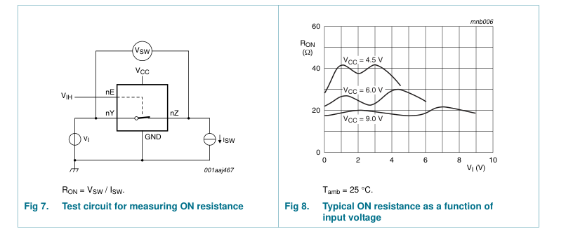
Table 8. ON resistance for 74HC2G66 and 74HCT2G66 At recommended operating conditions; voltages are referenced to GND (ground 0 V); for graph see Figure 8.
| Symbol | Parameter | Conditions | −40 °C to +85 °C | − to | 40 °C +125 °C | Unit | ||||
|---|---|---|---|---|---|---|---|---|---|---|
| Min | Typ[2] | Ma | x | Min | Max |
74HC2G66[1] RON(peak) ON resistance (peak)
VI = GND to VCC; see Figure 7 and 8 ISW = 0.1 mA; VCC = 2.0 V
- 250 - - - Ω
ISW = 1.0 mA; VCC = 4.5 V
- 41 118 - 142 Ω
ISW = 1.0 mA; VCC = 6.0 V
- 30 105 - 126 Ω
ISW = 1.0 mA; VCC = 9.0 V
- 21 88 - 105 Ω
ON resistance (rail)
VI = GND; see Figure 7 and 8
RON(rail)
ISW = 0.1 mA; VCC = 2.0 V
- 65 - - - Ω
ISW = 1.0 mA; VCC = 4.5 V
- 28 95 - 115 Ω
ISW = 1.0 mA; VCC = 6.0 V
- 22 82 - 100 Ω
ISW = 1.0 mA; VCC = 9.0 V
- 18 70 - 80 Ω
VI = VCC; see Figure 7 and 8 ISW = 0.1 mA; VCC = 2.0 V
- 65 - - - Ω
ISW = 1.0 mA; VCC = 4.5 V
- 31 106 - 128 Ω
ISW = 1.0 mA; VCC = 6.0 V
- 23 94 - 113 Ω
ISW = 1.0 mA; VCC = 9.0 V
- 19 78 - 95 Ω
ON resistance mismatch
VI = VCC to GND; see Figure 7 and 8
ΔRON between channels
VCC = 4.5 V
- 5 - - - Ω
VCC = 6.0 V
- 4 - - - Ω
VCC = 9.0 V
- 3 - - - Ω
74HCT2G66
ON resistance (peak)
VI = GND to VCC; see Figure 7 and 8
RON(peak)
ISW = 1.0 mA; VCC = 4.5 V
- 41 118 - 142 Ω
ON resistance (rail)
VI = GND; see Figure 7 and 8
RON(rail)
ISW = 1.0 mA; VCC = 4.5 V
- 28 95 - 115 Ω
VI = VCC; see Figure 7 and 8 ISW = 1.0 mA; VCC = 4.5 V
- 31 106 - 128 Ω
ON resistance mismatch
VI = VCC to GND; see Figure 7 and 8
ΔRON between channels
VCC = 4.5 V
- 5 - - - Ω
[1] At supply voltages approaching 2 V, the ON resistance becomes extremely non-linear. Therefore it is recommended that these devices be used to transmit digital signals only, when using this supply voltage. [2] Typical values are measured at Tamb = 25 °C.
6 of 21
Page 7
10.3 ON resistance test circuit and graphs
11. Dynamic characteristics
Table 9. Dynamic characteristics Voltages are referenced to GND (ground = 0 V); For test circuit see Figure 11.
| Column 1 | Column 2 | Column 3 | Column 4 | Column 5 | Column 6 |
|---|---|---|---|---|---|
| −40 °C to +85 °C | −40 °C to +125 °C | ||||
| Min | Typ[1] | Max | Min | Max |
Symbol Parameter
Conditions
Unit
74HC2G66
[2]
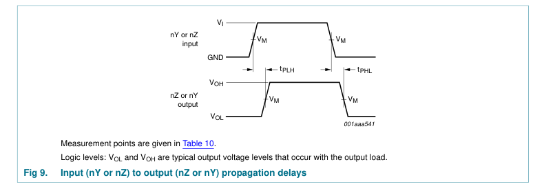
propagation delay nY to nZ or nZ to nY; RL = ∞ Ω; tpd
see Figure 9 VCC = 2.0 V
- 6.5 65 - 80 ns
VCC = 4.5 V
- 2 13 - 15 ns
VCC = 6.0 V
- 1.5 11 - 14 ns
VCC = 9.0 V
- 1.2 10 - 12 ns
[2]
enable time
nE to nY or nZ; see Figure 10
ten
VCC = 2.0 V
- 40 125 - 150 ns
VCC = 4.5 V
- 12 29 - 30 ns
VCC = 6.0 V
- 10 21 - 26 ns
VCC = 9.0 V
- 7 16 - 20 ns
[2]
disable time
nE to nY or nZ; see Figure 10
tdis
VCC = 2.0 V
- 21 145 - 175 ns
VCC = 4.5 V
- 12 29 - 35 ns
VCC = 6.0 V
- 11 28 - 33 ns
VCC = 9.0 V
- 10 23 - 27 ns
[3]
power dissipation
VI = GND to VCC
- 9 - - - pF
CPD capacitance
7 of 21
Page 8
Table 9. Dynamic characteristics …continued Voltages are referenced to GND (ground = 0 V); For test circuit see Figure 11. Symbol Parameter
Conditions
74HCT2G66
propagation delay nY to nZ or nZ to nY; RL = ∞ Ω; tpd
see Figure 9 VCC = 4.5 V
enable time
nE to nY or nZ; see Figure 10
ten
VCC = 4.5 V
disable time
nE to nY or nZ; see Figure 10
tdis
VCC = 4.5 V
power dissipation
VI = GND to VCC − 1.5 V
CPD capacitance
[1] All typical values are measured at Tamb = 25 °C. [2] tpd is the same as tPLH and tPHL. ten is the same as tPZL and tPZH. tdis is the same as tPLZ and tPHZ. [3] CPD is used to determine the dynamic power dissipation PD (μW). PD = CPD × VCC2 × fi + Σ((CL × CSW) × VCC2 × fo) where: fi = input frequency in MHz; fo = output frequency in MHz; CL = output load capacitance in pF; CSW = maximum switch capacitance in pF (see Table 7); VCC = supply voltage in volts; Σ((CL × CSW) × VCC2 × fo) = sum of outputs.
11.1 Waveforms and test circuit
−40 °C to +85 °C
−40 °C to +125 °C Unit
Min Typ[1] Max
Min Max
[2]
- 2 15 - 18 ns
[2]
- 13 30 - 36 ns
[2]
- 13 44 - 53 ns
[3] - 9 - - - pF
8 of 21
Page 9
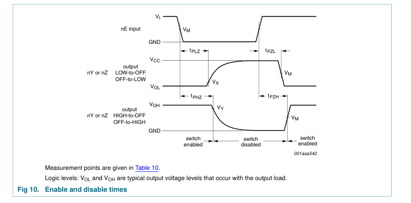
Table 10. Measurement points
| Type | Input | Output | ||
|---|---|---|---|---|
| V M | V M | V X | V Y |
74HC2G66
0.5VCC
0.5VCC
VOL + 10 %
VOH − 10 %
VOL + 10 %
VOH − 10 %
74HCT2G66
1.3 V
1.3 V
9 of 21
Page 10
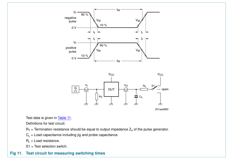
Table 11. Test data
| Type | Input | Load | S1 position | ||||
|---|---|---|---|---|---|---|---|
| V I | t, t[1] r f | C L | R L | t , t PHL PLH | t , t PZH PHZ | t , t PZL PLZ |
74HC2G66
GND to VCC
6 ns
50 pF
1 kΩ
open
GND
VCC
74HCT2G66 GND to 3 V 6 ns
50 pF
1 kΩ
open
GND
VCC
[1] There is no constraint on tr, tf with a 50 % duty factor when measuring fmax.
11.2 Additional dynamic characteristics
Table 12. Additional dynamic characteristics for 74HC2G66 and 74HCT2G66 GND = 0 V; tr = tf = 6.0 ns; CL = 50 pF; unless otherwise specified. All typical values are measured at Tamb = 25 °C. Symbol Parameter
Conditions
Min
Typ
Max Unit
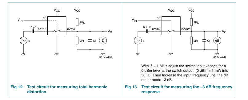
fi = 1 kHz; RL = 10 kΩ; see Figure 12
%
THD total harmonic distortion
VCC = 4.5 V; VI = 4.0 V (p-p)
-
0.04
- %
VCC = 9.0 V; VI = 8.0 V (p-p)
-
0.02
- %
fi = 10 kHz; RL = 10 kΩ; see Figure 12 VCC = 4.5 V; VI = 4.0 V (p-p)
-
0.12
- %
VCC = 9.0 V; VI = 8.0 V (p-p)
-
0.06
- %
10 of 21
Page 11
Table 12. Additional dynamic characteristics for 74HC2G66 and 74HCT2G66 …continued GND = 0 V; tr = tf = 6.0 ns; CL = 50 pF; unless otherwise specified. All typical values are measured at Tamb = 25 °C. Symbol Parameter
Conditions
Min
Typ
Max Unit
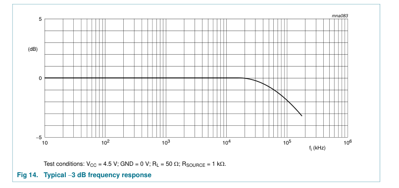
f(−3dB) −3 dB frequency
RL = 50 Ω; CL = 10 pF;
response
see Figure 13 and 14 VCC = 4.5 V
-
180
- MHz
VCC = 9.0 V
-
200
- MHz
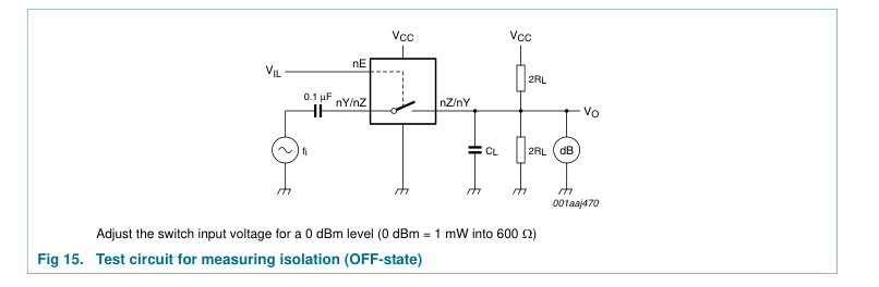
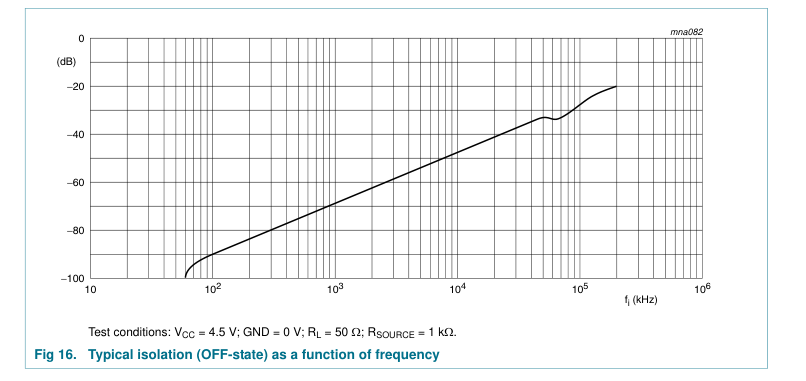
isolation (OFF-state)
RL = 600 Ω; fi = 1 MHz;
αiso
see Figure 15 and 16 VCC = 4.5 V
-
−50
- dB
VCC = 9.0 V
-
−50
- dB
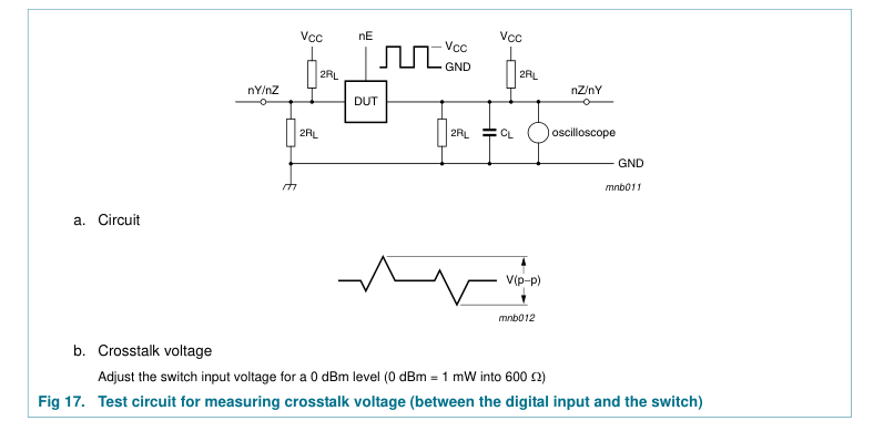
crosstalk voltage
between digital input and switch (peak
Vct
to peak value); RL = 600 Ω; fi = 1 MHz; see Figure 17 VCC = 4.5 V
-
110
- mV
VCC = 9.0 V
-
220
- mV
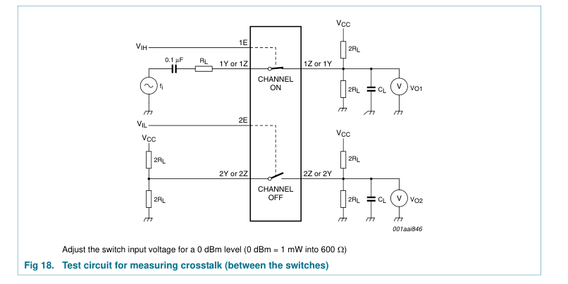
between switches; RL = 600 Ω;
Xtalk crosstalk
fi = 1 MHz; see Figure 18 VCC = 4.5 V
-
−60
- dB
VCC = 9.0 V
-
−60
- dB
11.3 Test circuits and graphs
11 of 21
Page 12
12 of 21
Page 13
13 of 21
Page 14
14 of 21
Page 15
12. Package outline
TSSOP8: plastic thin shrink small outline package; 8 leads; body width 3 mm; lead length 0.5 mm
SOT505-2
D
E
A X
c
HE
v M A
y
Z
5
8
A2 A
(A3)
A1
pin 1 index
θ Lp L
1
4
detail X
w M
e bp
0
2.5
5 mm
scale
DIMENSIONS (mm are the original dimensions)
| UNIT | A max. | A1 | A2 | A3 | bp | c | D(1) | E(1) | e | HE | L | Lp | v | w | y | Z(1) | θ |
|---|---|---|---|---|---|---|---|---|---|---|---|---|---|---|---|---|---|
| mm | 1.1 | 0.15 0.00 | 0.95 0.75 | 0.25 | 0.38 0 0.22 0 | .18 .08 | 3.1 2.9 | 3.1 2.9 | 0.65 | 4.1 3.9 | 0.5 | 0.47 0.33 | 0.2 | 0.13 | 0.1 | 0.70 0.35 | 8° 0° |
Note 1. Plastic or metal protrusions of 0.15 mm maximum per side are not included.
REFERENCES
OUTLINE
EUROPEAN
ISSUE DATE
VERSION
PROJECTION
IEC
JEDEC
JEITA
02-01-16
SOT505-2
- - -
Fig 19. Package outline SOT505-2 (TSSOP8)
15 of 21
Page 16
VSSOP8: plastic very thin shrink small outline package; 8 leads; body width 2.3 mm
SOT765-1
D
E
A X
c
y
HE
v M A
Z
5
8
Q
A2 A A1
(A3)
pin 1 index
θ Lp L
1
4
detail X
e
w M bp
0
2.5
5 mm
scale
DIMENSIONS (mm are the original dimensions)
| UNIT | A max. | A1 | A2 | A3 | bp | c | D(1) | E(2) | e | HE | L | Lp | Q | v | w | y | Z(1) | θ |
|---|---|---|---|---|---|---|---|---|---|---|---|---|---|---|---|---|---|---|
| mm | 1 | 0.15 0.00 | 0.85 0.60 | 0.12 | 0.27 0.17 | 0.23 0.08 | 2.1 1.9 | 2.4 2.2 | 0.5 | 3.2 3.0 | 0.4 | 0.40 0.15 | 0.21 0.19 | 0.2 | 0.13 | 0.1 | 0.4 0.1 | 8° 0° |
Notes 1. Plastic or metal protrusions of 0.15 mm maximum per side are not included. 2. Plastic or metal protrusions of 0.25 mm maximum per side are not included.
REFERENCES
OUTLINE
EUROPEAN
ISSUE DATE
VERSION
PROJECTION
IEC
JEDEC
JEITA
02-06-07
SOT765-1
MO-187
Fig 20. Package outline SOT765-1 (VSSOP8)
16 of 21
Page 17
XSON8U: plastic extremely thin small outline package; no leads;
SOT996-2
8 terminals; UTLP based; body 3 x 2 x 0.5 mm
B A
D
A
E
A1
detail X
terminal 1 index area
e1
C
C A B v M b e
L1
y
y1
w M C
C
1
4
L2
L
8
5
X
0 1 2 mm
scale
DIMENSIONS (mm are the original dimensions)
| UNIT | A max | A1 | b | D | E | e | e1 | L | L1 | L2 | v | w | y | y1 |
|---|---|---|---|---|---|---|---|---|---|---|---|---|---|---|
| mm | 0.5 | 0.05 0.00 | 0.35 0.15 | 2.1 1.9 | 3.1 2.9 | 0.5 | 1.5 | 0.5 0.3 | 0.15 0.05 | 0.6 0.4 | 0.1 | 0.05 | 0.05 | 0.1 |
| Column 1 | Column 2 | Column 3 | Column 4 | Column 5 | Column 6 | Column 7 |
|---|---|---|---|---|---|---|
| OUTLINE VERSION | REFERENCES IEC JEDEC JEITA | EUROPEAN PROJECTION | ISSUE DATE | |||
| IEC | JEDEC | JEITA | ||||
| SOT996-2 | - - - | - - - | 07-12-18 07-12-21 |
Fig 21. Package outline SOT996-2 (XSON8U)
17 of 21
Page 18
13. Abbreviations
Table 13. Abbreviations Acronym
Description
CMOS
Complementary Metal-Oxide Semiconductor
ESD
ElectroStatic Discharge
HBM
Human Body Model
MM
Machine Model
TTL
Transistor-Transistor Logic
DUT
Device Under Test
14. Revision history
Table 14. Revision history Document ID
Release date
Data sheet status
Change notice
Supersedes
20100402
-
74HC_HCT2G66_5
- Added type number 74HC2G66GD and 74HCT2G66GD (XSON8U package)
Modifications: 74HC_HCT2G66_5
20090126
-
74HC_HCT2G66_4
- The format of this data sheet has been redesigned to comply with the new identity
Modifications:
guidelines of NXP Semiconductors.
- Legal texts have been adapted to the new company name where appropriate.
- Table 1 “Ordering information” and Section 12 “Package outline” package SOT765-1 added.
- Quick Reference Data and Soldering sections removed.
- Section 2 “Features and benefits” updated.
74HC_HCT2G66_4
20040519
Product specification
-
74HC_HCT2G66_3
20031126
Product specification
-
74HC_HCT2G66_2
20030808
Product specification
-
74HC_HCT2G66_1
20030625
Product specification
-
74HC_HCT2G66_3 74HC_HCT2G66_2 74HC_HCT2G66_1 -
18 of 21
Page 19
15. Legal information
15.1 Data sheet status
Document status[1][2]
Product status[3]
Definition This document contains data from the objective specification for product development.
Objective [short] data sheet
Development
This document contains data from the preliminary specification.
Preliminary [short] data sheet Qualification
This document contains the product specification.
Product [short] data sheet
Production
[1] Please consult the most recently issued document before initiating or completing a design. [2] The term ‘short data sheet’ is explained in section “Definitions”. [3] The product status of device(s) described in this document may have changed since this document was published and may differ in case of multiple devices. The latest product status information is available on the Internet at URL http://www.nxp.com.
15.2 Definitions
Draft — The document is a draft version only. The content is still under internal review and subject to formal approval, which may result in modifications or additions. NXP Semiconductors does not give any representations or warranties as to the accuracy or completeness of information included herein and shall have no liability for the consequences of use of such information. Short data sheet — A short data sheet is an extract from a full data sheet with the same product type number(s) and title. A short data sheet is intended for quick reference only and should not be relied upon to contain detailed and full information. For detailed and full information see the relevant full data
sheet, which is available on request via the local NXP Semiconductors sales office. In case of any inconsistency or conflict with the short data sheet, the full data sheet shall prevail. Product specification — The information and data provided in a Product data sheet shall define the specification of the product as agreed between NXP Semiconductors and its customer, unless NXP Semiconductors and customer have explicitly agreed otherwise in writing. In no event however, shall an agreement be valid in which the NXP Semiconductors product is deemed to offer functions and qualities beyond those described in the Product data sheet.
15.3 Disclaimers
Limited warranty and liability — Information in this document is believed to be accurate and reliable. However, NXP Semiconductors does not give any representations or warranties, expressed or implied, as to the accuracy or completeness of such information and shall have no liability for the consequences of use of such information. In no event shall NXP Semiconductors be liable for any indirect, incidental, punitive, special or consequential damages (including - without limitation - lost profits, lost savings, business interruption, costs related to the removal or replacement of any products or rework charges) whether or not such damages are based on tort (including negligence), warranty, breach of
contract or any other legal theory. Notwithstanding any damages that customer might incur for any reason whatsoever, NXP Semiconductors’ aggregate and cumulative liability towards customer for the products described herein shall be limited in accordance with the Terms and conditions of commercial sale of NXP Semiconductors. Right to make changes — NXP Semiconductors reserves the right to make changes to information published in this document, including without limitation specifications and product descriptions, at any time and without notice. This document supersedes and replaces all information supplied prior to the publication hereof. Suitability for use in automotive applications — This NXP
Semiconductors product has been qualified for use in automotive applications. The product is not designed, authorized or warranted to be
suitable for use in medical, military, aircraft, space or life support equipment, nor in applications where failure or malfunction of an NXP Semiconductors product can reasonably be expected to result in personal injury, death or severe property or environmental damage. NXP Semiconductors accepts no liability for inclusion and/or use of NXP Semiconductors products in such equipment or applications and therefore such inclusion and/or use is at the customer’s own risk. Applications — Applications that are described herein for any of these products are for illustrative purposes only. NXP Semiconductors makes no representation or warranty that such applications will be suitable for the
specified use without further testing or modification. NXP Semiconductors does not accept any liability related to any default, damage, costs or problem which is based on a weakness or default in the customer application/use or the application/use of customer’s third party customer(s) (hereinafter both referred to as “Application”). It is customer’s sole responsibility to check whether the NXP Semiconductors product is suitable and fit for the Application planned. Customer has to do all necessary testing for the Application in order to avoid a default of the Application and the product. NXP Semiconductors does not accept any liability in this respect.
Limiting values — Stress above one or more limiting values (as defined in the Absolute Maximum Ratings System of IEC 60134) will cause permanent damage to the device. Limiting values are stress ratings only and (proper) operation of the device at these or any other conditions above those given in the Recommended operating conditions section (if present) or the Characteristics sections of this document is not warranted. Constant or repeated exposure to limiting values will permanently and irreversibly affect the quality and reliability of the device. Terms and conditions of commercial sale — NXP Semiconductors products are sold subject to the general terms and conditions of commercial
sale, as published at http://www.nxp.com/profile/terms, unless otherwise agreed in a valid written individual agreement. In case an individual agreement is concluded only the terms and conditions of the respective agreement shall apply. NXP Semiconductors hereby expressly objects to applying the customer’s general terms and conditions with regard to the purchase of NXP Semiconductors products by customer. No offer to sell or license — Nothing in this document may be interpreted or construed as an offer to sell products that is open for acceptance or the grant, conveyance or implication of any license under any copyrights, patents or other industrial or intellectual property rights.
Export control — This document as well as the item(s) described herein may be subject to export control regulations. Export might require a prior authorization from national authorities.
15.4 Trademarks
Notice: All referenced brands, product names, service names and trademarks are the property of their respective owners.
19 of 21
Page 20
16. Contact information
For more information, please visit: http://www.nxp.com For sales office addresses, please send an email to: salesaddresses@nxp.com
20 of 21
Page 21
17. Contents
1 General description . . . . . . . . . . . . . . . . . . . . . . 1 2 Features and benefits . . . . . . . . . . . . . . . . . . . . 1 3 Ordering information. . . . . . . . . . . . . . . . . . . . . 1 4 Marking . . . . . . . . . . . . . . . . . . . . . . . . . . . . . . . . 2 5 Functional diagram . . . . . . . . . . . . . . . . . . . . . . 2 6 Pinning information. . . . . . . . . . . . . . . . . . . . . . 2 6.1 Pinning . . . . . . . . . . . . . . . . . . . . . . . . . . . . . . . 2 6.2 Pin description . . . . . . . . . . . . . . . . . . . . . . . . . 3 7 Functional description . . . . . . . . . . . . . . . . . . . 3 8 Limiting values. . . . . . . . . . . . . . . . . . . . . . . . . . 3
9 Recommended operating conditions. . . . . . . . 4 10 Static characteristics. . . . . . . . . . . . . . . . . . . . . 4 10.1 Test circuits. . . . . . . . . . . . . . . . . . . . . . . . . . . . 5 10.2 ON resistance. . . . . . . . . . . . . . . . . . . . . . . . . . 6 10.3 ON resistance test circuit and graphs. . . . . . . . 7 11 Dynamic characteristics . . . . . . . . . . . . . . . . . . 7 11.1 Waveforms and test circuit . . . . . . . . . . . . . . . . 8 11.2 Additional dynamic characteristics . . . . . . . . . 10 11.3 Test circuits and graphs . . . . . . . . . . . . . . . . . 11 12 Package outline . . . . . . . . . . . . . . . . . . . . . . . . 15 13 Abbreviations. . . . . . . . . . . . . . . . . . . . . . . . . . 18
14 Revision history. . . . . . . . . . . . . . . . . . . . . . . . 18 15 Legal information. . . . . . . . . . . . . . . . . . . . . . . 19 15.1 Data sheet status . . . . . . . . . . . . . . . . . . . . . . 19 15.2 Definitions. . . . . . . . . . . . . . . . . . . . . . . . . . . . 19 15.3 Disclaimers . . . . . . . . . . . . . . . . . . . . . . . . . . . 19 15.4 Trademarks. . . . . . . . . . . . . . . . . . . . . . . . . . . 19 16 Contact information. . . . . . . . . . . . . . . . . . . . . 20 17 Contents . . . . . . . . . . . . . . . . . . . . . . . . . . . . . . 21
Please be aware that important notices concerning this document and the product(s) described herein, have been included in section ‘Legal information’.
© NXP B.V. 2010.
All rights reserved.
For more information, please visit: http://www.nxp.com For sales office addresses, please send an email to: salesaddresses@nxp.com
Date of release: 2 April 2010 Document identifier: 74HC_HCT2G66_6