Download PDF
74HC251 PHILIPS
Document overview
- PDF pages: 7
Technical content
Page 1
Page 2
FEATURES
- True and complement outputs
- Both outputs are 3-state for further multiplexer expansion
- Multifunction capability
- Permits multiplexing from n-lines to one line
- Output capability: standard
- ICC category: MSI
GENERAL DESCRIPTION
The 74HC/HCT251 are high-speed Si-gate CMOS devices and are pin compatible with low power Schottky TTL (LSTTL). They are specified in compliance with JEDEC standard no. 7A.
QUICK REFERENCE DATA
GND = 0 V; Tamb = 25 °C; tr = tf = 6 ns
The 74HC/HCT251 are the logic implementations of single-pole 8-position switches with the state of three select inputs (S0, S1, S2) controlling the switch positions. Assertion (Y) and negation (Y) outputs are both provided. The output enable input (OE) is active LOW. The logic function provided at the output, when activated, is: Y = OE.(I0.S0.S1.S2 + I1.S0.S1.S2 + + I2.S0.S1.S2 + I3.S0.S1.S2 + + I4.S0.S1.S2 + I5.S0.S1.S2 + + I6.S0.S1.S2 + I7.S0.S1.S2) Both outputs are in the high impedance OFF-state (Z) when the output enable input is HIGH, allowing multiplexer expansion by tying the outputs.
| SYMBOL | PARAMETER | CONDITIONS | TYPICAL | UNIT | |
|---|---|---|---|---|---|
| HC | HCT | ||||
| t / t PHL PLH | propagation delay I to Y n I to Y n S to Y n S to Y n | C = 15 pF; V = 5 V L CC | 15 17 20 21 | 19 19 20 21 | ns ns ns ns |
| C I | input capacitance | 3.5 | 3.5 | pF | |
| C PD | power dissipation capacitance per package | notes 1 and 2 | 44 | 46 | pF |
Notes 1. CPD is used to determine the dynamic power dissipation (PD in µW): PD = CPD × VCC2 × fi + ∑ (CL × VCC2 × fo) where: fi = input frequency in MHz fo = output frequency in MHz ∑ (CL × VCC2 × fo) = sum of outputs CL = output load capacitance in pF VCC = supply voltage in V 2. For HC the condition is VI = GND to VCC For HCT the condition is VI = GND to VCC − 1.5 V
ORDERING INFORMATION
See “74HC/HCT/HCU/HCMOS Logic Package Information”.
Page 3
PIN DESCRIPTION
| PIN NO. | SYMBOL | NAME AND FUNCTION |
|---|---|---|
| 4, 3, 2, 1, 15, 14, 13, 12 5 6 7 8 11, 10, 9 16 | I to I 0 7 Y Y OE GND S , S , S 0 1 2 V CC | multiplexer inputs multiplexer output complementary multiplexer output 3-state output enable input (active LOW) ground (0 V) select inputs positive supply voltage |
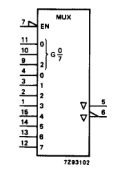
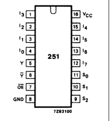
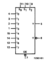
Fig.2 Logic symbol.
Fig.1 Pin configuration.
Fig.3 IEC logic symbol.
Page 4
FUNCTION TABLE
| Column 1 | Column 2 | Column 3 | Column 4 | Column 5 | Column 6 | Column 7 | Column 8 | Column 9 | Column 10 | Column 11 | Column 12 | Column 13 | Column 14 |
|---|---|---|---|---|---|---|---|---|---|---|---|---|---|
| INPUTS | OUTPUTS | ||||||||||||
| OE | S 2 | S 1 | S 0 | I 0 | I 1 | I 2 | I 3 | I 4 | I 5 | I 6 | I 7 | Y | Y |
| H | X | X | X | X | X | X | X | X | X | X | X | Z | Z |
| L L L L | L L L L | L L L L | L L H H | L H X X | X X L H | X X X X | X X X X | X X X X | X X X X | X X X X | X X X X | H L H L | L H L H |
| L L L L | L L L L | H H H H | L L H H | X X X X | X X X X | L H X X | X X L H | X X X X | X X X X | X X X X | X X X X | H L H L | L H L H |
| L L L L | H H H H | L L L L | L L H H | X X X X | X X X X | X X X X | X X X X | L H X X | X X L H | X X X X | X X X X | H L H L | L H L H |
| L L L L | H H H H | H H H H | L L H H | X X X X | X X X X | X X X X | X X X X | X X X X | X X X X | L H X X | X X L H | H L H L | L H L H |
Note 1. H = HIGH voltage level L = LOW voltage level X = don’t care Z = high impedance OFF-state
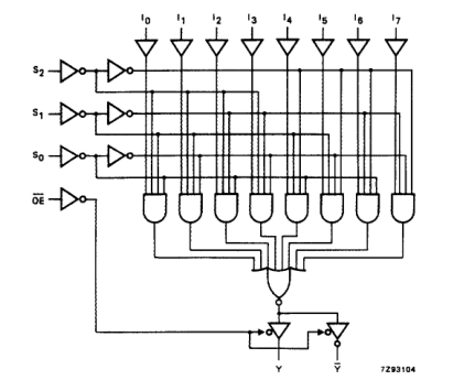
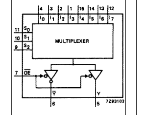
Fig.4 Functional diagram.
Fig.5 Logic diagram.
Page 5
DC CHARACTERISTICS FOR 74HC
For the DC characteristics see “74HC/HCT/HCU/HCMOS Logic Family Specifications”. Output capability: standard ICC category: MSI
AC CHARACTERISTICS FOR 74HC
GND = 0 V; tr = tf = 6 ns; CL = 50 pF
| SYMBOL | PARAMETER | T (°C) amb | UNIT | TEST CONDITIONS | |||||||
|---|---|---|---|---|---|---|---|---|---|---|---|
| 74HC | V CC (V) | WAVEFORMS | |||||||||
| +25 | −40 to +85 | −40 to +125 | |||||||||
| min. | typ. | max. | min. | max. | min. | max. | |||||
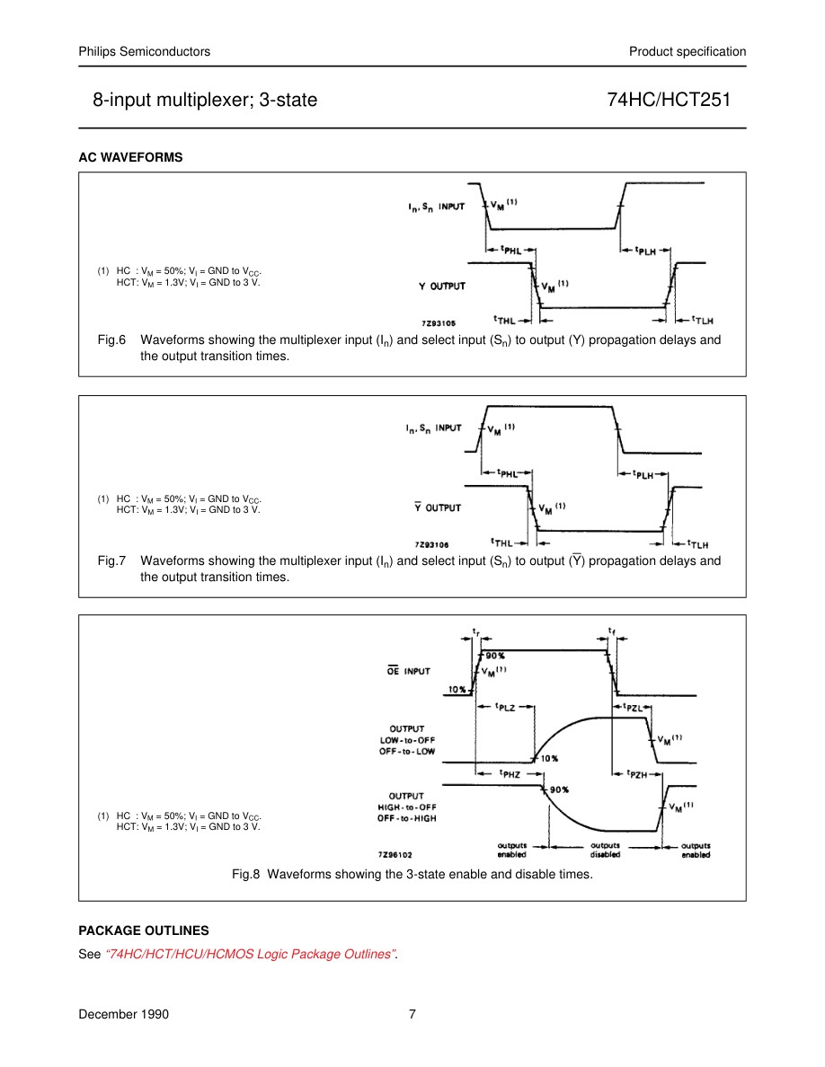
| t / t PHL PLH | propagation delay I to Y n | 50 18 14 | 170 34 29 | 215 43 37 | 255 51 43 | ns | 2.0 4.5 6.0 | Fig.6 | |||
| t / t PHL PLH | propagation delay I to Y n | 55 20 16 | 175 35 30 | 220 44 37 | 265 53 45 | ns | 2.0 4.5 6.0 | Fig.7 | |||
| t / t PHL PLH | propagation delay S to Y n | 66 24 19 | 205 41 35 | 255 51 43 | 310 62 53 | ns | 2.0 4.5 6.0 | Fig.6 | |||
| t / t PHL PLH | propagation delay S to Y n | 69 25 20 | 205 41 35 | 255 51 43 | 310 62 53 | ns | 2.0 4.5 6.0 | Fig.7 | |||
| t / t PZH PZL | 3-state output enable time OE to Y, Y | 36 13 10 | 140 28 24 | 175 35 30 | 210 42 36 | ns | 2.0 4.5 6.0 | Fig.7 | |||
| t / t PHZ PLZ | 3-state output disable time OE to Y, Y | 39 14 11 | 140 28 24 | 170 35 30 | 210 42 36 | ns | 2.0 4.5 6.0 | Fig.7 | |||
| t / t THL TLH | output transition time | 19 7 6 | 75 15 13 | 95 19 16 | 110 22 19 | ns | 2.0 4.5 6.0 | Figs 6 and 7 |
Page 6
DC CHARACTERISTICS FOR 74HCT
For the DC characteristics see “74HC/HCT/HCU/HCMOS Logic Family Specifications”. Output capability: standard ICC category: MSI
Note to HCT types The value of additional quiescent supply current (∆ICC) for a unit load of 1 is given in the family specifications. To determine ∆ICC per input, multiply this value by the unit load coefficient shown in the table below.
| INPUT | UNIT LOAD COEFFICIENT |
|---|---|
| I n S 0 S , S 1 2 OE | 1.00 1.50 1.50 1.50 |
AC CHARACTERISTICS FOR HCT
GND = 0 V; tr = tf = 6 ns; CL = 50 pF
| SYMBOL | PARAMETER | T (°C) amb | UNIT | TEST CONDITIONS | |||||||
|---|---|---|---|---|---|---|---|---|---|---|---|
| 74HCT | V CC (V) | WAVEFORMS | |||||||||
| +25 | −40 to +85 | −40 to +125 | |||||||||
| min. | typ. | max. | min. | max. | min. | max. | |||||
| t / t PHL PLH | propagation delay I to Y n | 22 | 35 | 44 | 53 | ns | 4.5 | Fig.6 | |||
| t / t PHL PLH | propagation delay I to Y n | 22 | 35 | 44 | 53 | ns | 4.5 | Fig.7 | |||
| t / t PHL PLH | propagation delay S to Y n | 24 | 44 | 55 | 66 | ns | 4.5 | Fig.6 | |||
| t / t PHL PLH | propagation delay S to Y n | 25 | 44 | 55 | 66 | ns | 4.5 | Fig.7 | |||
| t / t PZH PZL | 3-state output enable time OE to Y, Y | 13 | 28 | 35 | 42 | ns | 4.5 | Fig.7 | |||
| t / t PHZ PLZ | 3-state output disable time OE to Y, Y | 14 | 28 | 35 | 42 | ns | 4.5 | Fig.7 | |||
| t / t THL TLH | output transition time | 7 | 15 | 19 | 22 | ns | 4.5 | Figs 6 and 7 |
Page 7