Download PDF
HCMOS PHILIPS
Document overview
- PDF pages: 19
Technical content
Page 1
Page 2
GENERAL
These family specifications cover the common electrical ratings and characteristics of the entire HCMOS 74HC/HCT/HCU family, unless otherwise specified in the individual device data sheet.
INTRODUCTION
The 74HC/HCT/HCU high-speed Si-gate CMOS logic family combines the low power advantages of the HE4000B family with the high speed and drive capability of the low power Schottky TTL (LSTTL). The family will have the same pin-out as the 74 series and provide the same circuit functions. In these families are included several HE4000B family circuits which do not have TTL counterparts, and some special circuits. The basic family of buffered devices, designated as XX74HCXXXXX, will operate at CMOS input logic levels for high noise immunity, negligible typical quiescent supply and input current. It is operated from a power supply of 2 to 6 V.
RECOMMENDED OPERATING CONDITIONS FOR 74HC/HCT
FAMILY
SPECIFICATIONS
A subset of the family, designated as XX74HCTXXXXX, with the same features and functions as the “HC-types”, will operate at standard TTL power supply voltage (5 V ± 10%) and logic input levels (0.8 to 2.0 V) for use as pin-to-pin compatible CMOS replacements to reduce power consumption without loss of speed. These types are also suitable for converted switching from TTL to CMOS. Another subset, the XX74HCUXXXXX, consists of single-stage unbuffered CMOS compatible devices for application in RC or crystal controlled oscillators and other types of feedback circuits which operate in the linear mode.
HANDLING MOS DEVICES
Inputs and outputs are protected against electrostatic effects in a wide variety of device-handling situations. However, to be totally safe, it is desirable to take handling precautions into account (see also “HANDLING PRECAUTIONS”).
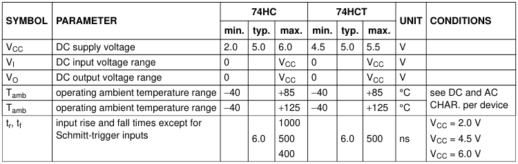
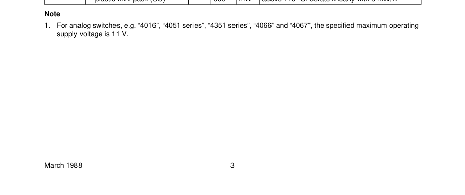
Note 1. For analog switches, e.g. “4016”, “4051 series”, “4351 series”, “4066” and “4067”, the specified maximum operating supply voltage is 10 V.
Page 3
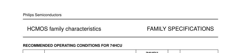
| SYMBOL | PARAMETER | 74HCU | UNIT | CONDITIONS | ||
|---|---|---|---|---|---|---|
| min. | typ. | max. | ||||
| V CC | DC supply voltage | 2.0 | 5.0 | 6.0 | V | |
| V I | DC input voltage range | 0 | V CC | V | ||
| V O | DC output voltage range | 0 | V CC | V | ||
| T amb | operating ambient temperature range | −40 | +85 | °C | see DC and AC CHAR. per device | |
| T amb | operating ambient temperature range | −40 | +125 | °C | ||

Page 4

Page 5

Page 6
Page 7
Page 8

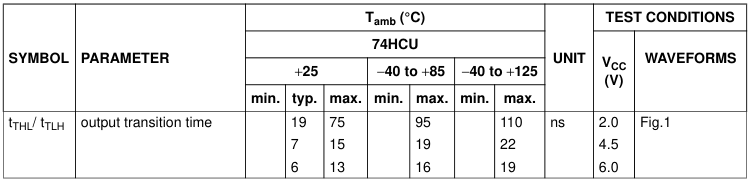

| SYMBOL | PARAMETER | T (°C) amb | UNIT | TEST CONDITIONS | |||||||
|---|---|---|---|---|---|---|---|---|---|---|---|
| 74HCT | V CC (V) | WAVEFORMS | |||||||||
| +25 | −40 to +85 | −40 to +125 | |||||||||
| min. | typ. | max. | min. | max. | min. | max. | |||||
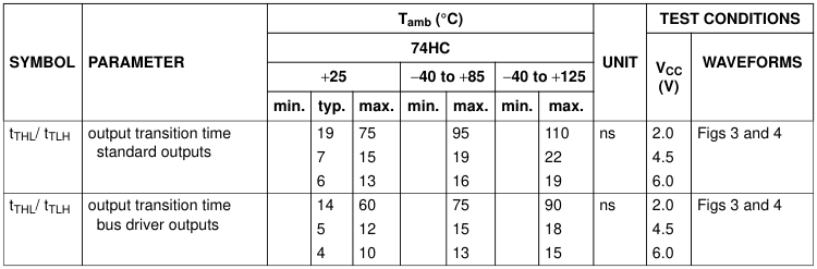
| t / t THL TLH | output transition time standard outputs | 7 | 15 | 19 | 22 | ns | 4.5 | Figs 8 and 9 | |||
| t / t THL TLH | output transition time bus driver outputs | 5 | 12 | 15 | 18 | ns | 4.5 | Figs 8 and 9 | |||
Page 9
Page 10
HC TYPES
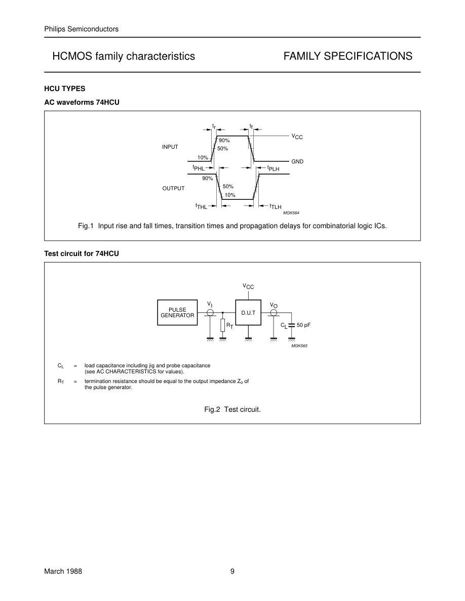
AC waveforms 74HC
tr tf
handbook, halfpage
VCC
90%
INPUT
50% 10%
GND
tPHL
tPLH
90% 50%
OUTPUT
10% tTHL
tTLH MGK564
Fig.3 Input rise and fall times, transition times and propagation delays for combinatorial logic ICs.
AC waveforms 74HC
1/fmax
handbook, full pagewidth
tr tf
VCC
90%
CLOCK
50%
INPUT 10 %
GND
tWH tWL th
th
VCC
DATA 50%
INPUT
GND
tsu
tsu
tTLH
tTHL
90%
OUTPUT
50% 10% tPLH
tPHL
trem
VCC
SET, RESET,
50%
PRESET INPUT
GND
MGK569
(1) In Fig.4 the active transition of the clock is going from LOW-to-HIGH and the active level of the forcing signals (SET, RESET and PRESET) is HIGH. The actual direction of the transition of the clock input and the actual active levels of the forcing signals are specified in the individual device data sheet. (2) For AC measurements: tr = tf = 6 ns; when measuring fmax, there is no constraint on tr, tf with 50% duty factor.
Fig.4 Set-up times, hold times, removal times, propagation delays and the maximum clock pulse frequency for
sequential logic ICs.
Page 11
Page 12
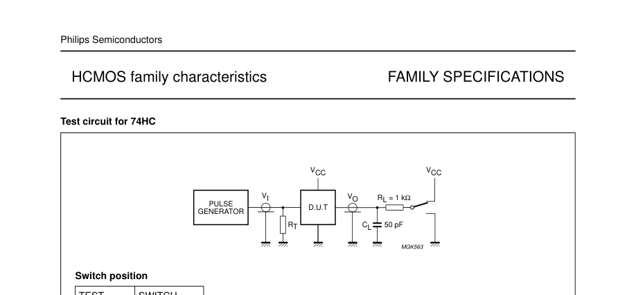

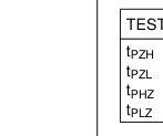
| TEST | SWITCH |
| t PZH t PZL t PHZ t PLZ | GND V CC GND V CC |
Page 13
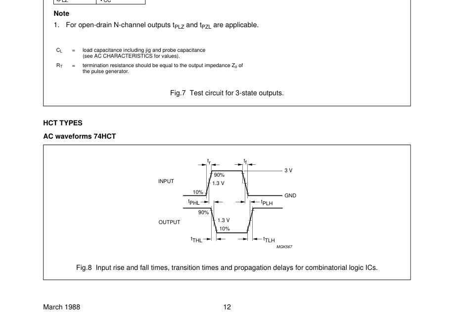
AC waveforms 74HCT
1/fmax
handbook, full pagewidth
tr tf
3 V
90%
CLOCK
1.3 V
INPUT 10%
GND
tWH tWL th
th
3 V
DATA 1.3 V
INPUT
GND
tsu
tsu
tTLH
tTHL
90%
OUTPUT
1.3 V 10% tPLH
tPHL
trem
3 V
SET, RESET,
1.3 V
PRESET INPUT
GND
MGK568
(1) In Fig.9 the active transition of the clock is going from LOW-to-HIGH and the active level of the forcing signals (SET, RESET and PRESET) is HIGH. The actual direction of the transition of the clock input and the actual active levels of the forcing signals are specified in the individual device data sheet. (2) For AC measurements: tr = tf = 6 ns; when measuring fmax, there is no constraint on tr, tf with 50% duty factor.
Fig.9 Set-up times, hold times, removal times, propagation delays and the maximum clock pulse frequency for
sequential logic ICs.
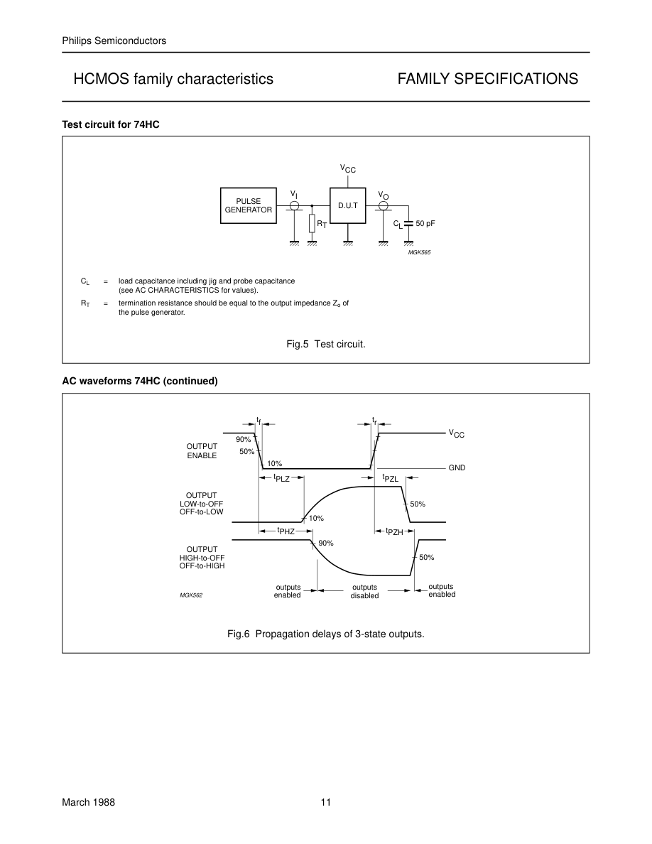
Test circuit for 74HCT
VCC
handbook, halfpage
VI
VO
PULSE
D.U.T
GENERATOR
RT
CL 50 pF
MGK565
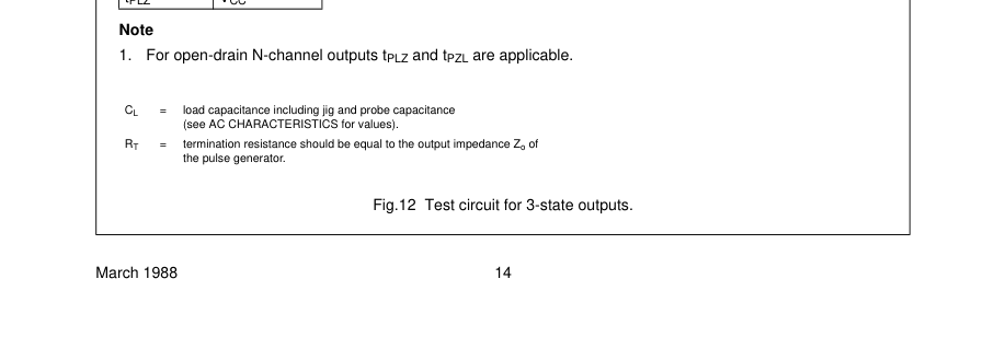
CL = load capacitance including jig and probe capacitance (see AC CHARACTERISTICS for values). = termination resistance should be equal to the output impedance Zo of RT the pulse generator.
Fig.10 Test circuit.
Page 14
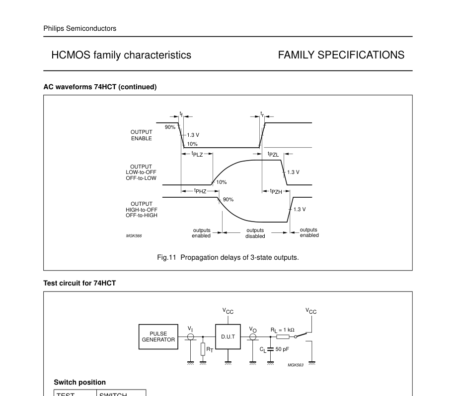

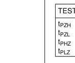
| TEST | SWITCH |
| t PZH t PZL t PHZ t PLZ | GND V CC GND V CC |
Page 15
DATA SHEET SPECIFICATION GUIDE
INTRODUCTION
The 74HCMOS data sheets have been designed for ease-of-use. A minimum of cross-referencing for more information is needed.
TYPICAL PROPAGATION DELAY AND FREQUENCY
The typical propagation delays listed at the top of the data sheets are the average of tPLH and tPHL for the longest data path through the device with a 15 pF load. For clocked devices, the maximum frequency of operation is also given. The typical operating frequency is the maximum device operating frequency with a 50% duty factor and no constraints on tr and tf.
LOGIC SYMBOLS
Two logic symbols are given for each device - the conventional one (Logic Symbol) which explicitly shows the internal logic (except for complex logic) and the IEC Logic Symbol as developed by the IEC (International Electrotechnical Commission). The IEC has been developing a very powerful symbolic language that can show the relationship of each input of a digital logic current to each output without explicitly showing the internal logic. Internationally, Working Group 2 of IEC Technical Committee TC-3 has prepared a new document (Publication 617-12) which supersedes Publication 117-15, published in 1972.
RATINGS
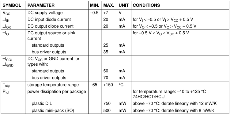
The “RATINGS” table (Limiting values in accordance with the Absolute Maximum System - IEC134) lists the maximum limits to which the device can be subjected without damage. This doesn’t imply that the device will function at these extreme conditions, only that, when these conditions are removed and the device operated within the Recommended Operating Conditions, it will still be functional and its useful life won’t have been shortened. The maximum rated supply voltage of 7 V is well below the typical breakdown voltage of 18 V.
RECOMMENDED OPERATING CONDITIONS
The “RECOMMENDED OPERATING CONDITIONS” table lists the operating ambient temperature and the
conditions under which the limits in the “DC CHARACTERISTICS” and “AC CHARACTERISTICS” tables will be met. The table should not be seen as a set of limits guaranteed by the manufacturer, but as the conditions used to test the devices and guarantee that they will then meet the limits in the DC and AC CHARACTERISTICS tables.
DC CHARACTERISTICS
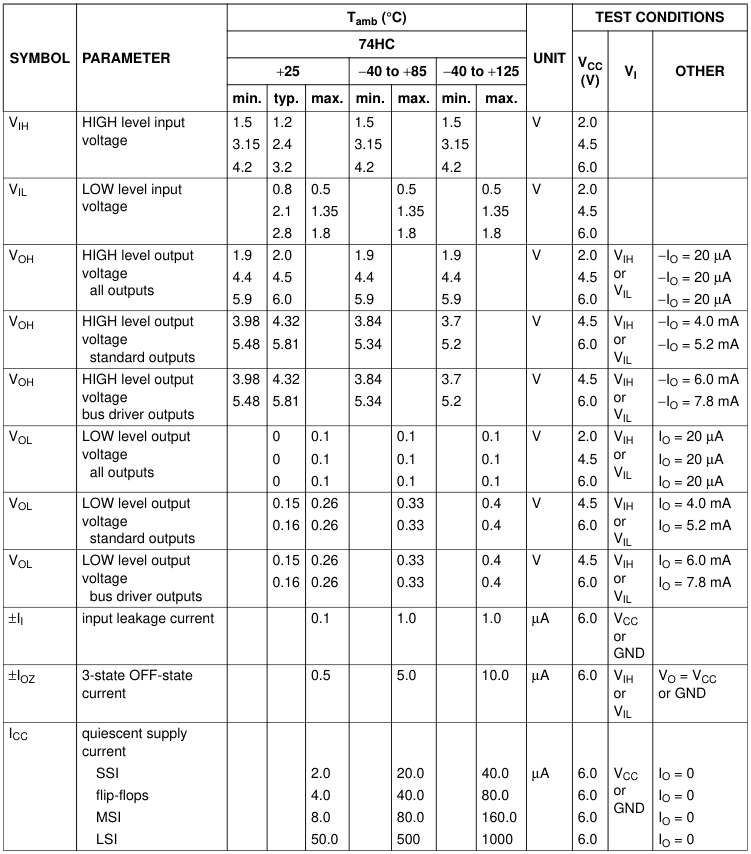
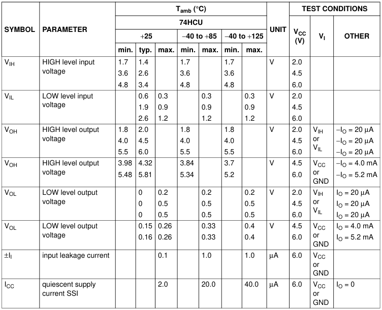
The “DC CHARACTERISTICS” table reflects the DC limits used during testing. The values published are guaranteed. The threshold values of VIH and VIL can be tested by the user. If VIH and VIL are applied to the inputs, the output voltages will be those published in the “DC CHARACTERISTICS” table. There is a tendency, by some, to use the published VIH and VIL thresholds to test a device for functionality in a “function-table exercizer” mode. This frequently causes problems because of the noise present at the test head of automated test equipment with cables up to 1 metre. Parametric tests, such as those used for the output levels under the VIH and VIL conditions are done fairly slowly, in the order of
milliseconds, so that there is no noise at the inputs when the outputs are measured. But in functionality testing, the outputs are measured much faster, so there can be noise on the inputs, before the device has assumed its final and correct output state. Thus, never use VIH and VIL to test the functionality of any HCMOS device type; instead, use input voltages of VCC (for the HIGH state) and 0 V (for the LOW state). In no way does this imply that the devices are noise-sensitive in the final system. In the data sheets, it may appear strange that the typical VIL is higher than the maximum VIL. However, this is because VILmax is the maximum VIL (guaranteed) for all
devices that will be recognized as a logic LOW. However, typically a higher VIL will also be recognized as a logic LOW. Conversely, the typical VIH is lower than its minimum guaranteed level. For 74HCMOS, unlike TTL, no output HIGH short-circuit current is specified. The use of this current, for example, to calculate propagation delays with capacitive loads, is covered by the HCMOS graphs showing the output drive capability and those showing the dependence of propagation delay on load capacitance. The quiescent supply current ICC is the leakage current of all the reversed-biased diodes and the OFF-state MOS transistors. It is measured with the inputs at VCC or GND
and is typically a few nA.
Page 16
AC CHARACTERISTICS
The “AC CHARACTERISTICS” table lists the guaranteed limits when a device is tested under the conditions given in the AC Test Circuits and Waveforms section.
TEST CIRCUITS
Good high-frequency wiring practices should be used in test circuits. Capacitor leads should be as short as possible to minimize ripples on the output waveform transitions and undershoot. Generous ground metal (preferably a ground-plane) should be used for the same reasons. A VCC decoupling capacitor should be provided at the test socket, also with short leads. Input signals should have rise and fall times of 6 ns, a signal swing of 0 V to VCC for 74HC and 0 V to 3 V for 74HCT; a 1.0 MHz square wave is recommended for most propagation delay tests. The repetition rate must be increased for testing fmax. Two pulse generators are usually required for testing
such parameters as set-up time, hold time and removal time. fmax is also tested with 6 ns input rise and fall times, with a 50% duty factor, but for typical fmax as high as 60 MHz, there are no constraints on rise and fall times.
Page 17
Page 18
Page 19