

 Download PDF
741 CTS
Document overview
- PDF pages: 5
Technical content
Page 1

Features
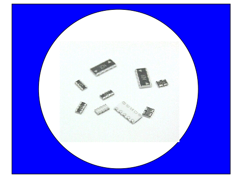
- Low Cost
- Thick Film Technology
- High Density Packaging
- Leadless Surface Mount Construction
- Tape and Reel Packaging
- Solder Coated Nickel Barrier Pads
- Isolated and Bussed Circuits
- Concave and Convex Terminations
- RoHS Compliant Version Available
Product Benefits
- High Density Packaging
Up to 30% less space per resistor than 0603 chip resistors Up to 75% less space per resistor than 0805 chip resistors
- Placement Efficiency
Networks require fewer placements than discrete components Larger overall size eases handling compared to discrete components
- Low Profile; Can be used in PCMCIA cards
Electrical and Mechanical Specifications
| Series | PCB Area (in²) Per Resistor | Circuit Type | Resistance Range, Ohms | 70°C Power Per Resistor* | Maximum Operating Voltage |
|---|---|---|---|---|---|
| 741 | 0.0015 | Isolated | 10 - 1M | .063W | 25V |
| 742 | 0.0037 | Isolated | 10 - 1M | .063W | 50V |
| 743 | 0.0071 | Isolated | 10 - 1M | .100W | 100V |
| 744 | 0.0094 | Isolated | 10 - 1M | .125W | 200V |
| 745 | 0.0058 | Bussed | 33 - 470K | .063W | 50V |
| 746 | 0.0013 | Bussed | 33 - 100K | .031W | 25V |
\*Total Rated Package Power equals total number of resistors times rated Power Per Resistor
Standard: ±5% or .5Ω (whichever is greater)
Resistance Tolerance Operating Temperature Range -55°C to +125°C
Standard: 200PPM/°C
Temperature Coefficient
Page 1 of 5
May 2006
Page 2
Package Outlines
Concave Termination – Type C
Convex Termination – Type X
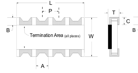
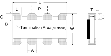
| Dimensions: mm/inch | ||||||||||||
| Part Code | Configuration | # Pads | # Res. | Circuit | L | W | P | T | A | B | C | D |
| 741X043 | 0402 X 2 | 4 | 2 | Isolated | 1.00 ±0.10 .039 ±.004 | 1.00 ±0.10 .039 ±.004 | 0.65 ±0.10 .026 ±.004 | 0.35 ±0.10 .014 ±.004 | 0.33 ±0.10 .013 ±.004 | 0.15 ±0.10 .006 ±.004 | 0.38 Max. .015 Max. | N/A |
| 741X083 | 0402 X 4 | 8 | 4 | Isolated | 2.00 ±0.10 .079 ±.004 | 0.50 ±0.10 .020 ±.004 | 0.30 ±0.15 .012 ±.006 | |||||
| 741C083 | 0402 X 4 | 8 | 4 | Isolated | 0.28 ±0.10 .011 ±.004 | |||||||
| 741X163 | 0402 X 8 | 16 | 8 | Isolated | 3.80 ±0.10 .150 ±.004 | 1.60 ±0.10 .063± .004 | 0.45 ±0.10 .018 ±.004 | 0.30 ±0.10 .012 ±.004 | 0.30 ±0.10 .012 ±.004 | 0.30 ±0.10 .012 ±.004 | ||
| 742C043 | 0603 X 2 | 4 | 2 | Isolated | 1.60 ±0.20 .063 ±.008 | 1.60 ±0.20 .063 ±.008 | 0.80 ±0.05 .032 ±.002 | 0.60 +0.10 -0.25 .024 +.004 -.010 | 0.50 ±0.15 .020 ±.006 | 0.30 ±0.20 .012 ±.008 | 0.40 ±0.15 .016 ±.006 | N/A |
| 742X083 742C083 | 0603 X 4 | 8 | 4 | Isolated | 3.20 ±0.20 .126 ±.008 | 0.30 ±0.15 .012 ±.006 | ||||||
| 742C163 | 0603 X 8 | 16 | 8 | Isolated | 6.40 ±0.20 .252 ±.008 | 0.40 ±0.15 .016 ±.006 | ||||||
| 743C043 | 0805 X 2 | 4 | 2 | Isolated | 2.54 ±0.20 .100 ±.008 | 2.00 ±0.20 .079 ±.008 | 1.27 ±0.05 .050 ±.002 | 0.60 ±0.10 .024 ±.004 | 0.80 ±0.10 .031 ±.006 | 0.40 ±0.20 .016 ±.008 | 0.40 ±0.15 .016 ±.006 | N/A |
| 743C083 | 0805 X 4 | 8 | 4 | Isolated | 5.08 ±0.30 .200 ±.012 | |||||||
| 744C043 | 1206 X 2 | 4 | 2 | Isolated | 2.54 ±0.20 .100 ±.008 | 3.20 ±0.20 .126 ±.008 | 1.27 ±0.05 .050 ±.002 | 0.60 ±0.10 .024 ±.004 | 0.80 ±0.10 .031 ±.006 | 0.50 ±0.20 .020 ±.008 | 0.50 ±0.15 .020 ±.006 | N/A |
| 744C083 | 1206 X 4 | 8 | 4 | Isolated | 5.08 ±0.30 .200 ±.012 | |||||||
| 745C101 745C102 | 10 | 8 | Bussed | 6.40 ±0.20 .252 ±.008 | 3.20 ±0.20 .126 ±.008 | 1.27 ±0.05 .050 ±.002 | 0.60 ±0.10 .024 ±.004 | 0.60 ±0.15 .024 ±.006 | 0.35 ±0.15 .013 ±.006 | 0.55 ±0.15 .022 ±.006 | N/A | |
| 745X101 745X102 | 10 | 8 | Bussed | 6.40 ±0.20 .252 ±.008 | 3.20 ±0.20 .126 ±.008 | 1.27 ±0.05 .050 ±.002 | 0.60 ±0.10 .024 ±.004 | 0.90 ±0.15 .035 ±.006 | 0.50 ±0.20 .020 ±.008 | 0.50 ±0.15 .020 ±.006 | 1.10 ±0.15 .043 ±.006 | |
| 746X101 | 10 | 8 | Bussed | 3.30 ±0.10 .130 ±.004 | 1.65 ±0.15 .065 ±.006 | 0.64 ±0.05 .025 ±.002 | 0.60 ±0.10 .024 ±.004 | 0.35 ±0.05 .014 ±.002 | 0.40 ±0.10 .016 ±.004 | 0.45 ±0.10 .018 ±.004 | 0.50 ±0.05 .020 ±.002 | |
May 2006
Page 2 of 5
Page 3
Types of Circuits
| 741C083 4 Resistors 8 Terminations 741X043 741X083 741X163 2 Resistors 4 Resistors 8 Resistors 4 Terminations 8 Terminations 16 Terminations | PAD 1 Mark PAD 1 Mark (Dot) (Triangle) 745C101 745C102 8 Resistors 8 Resistors 10 Terminations 10 Terminations Common Pad 50 mil pitch (1.27m m) Designator 745X101 745X102 8 R esisto rs 8 R esisto rs 10 T erm ina tio ns 10 T erm ina tio ns N ote: T he Marking Concept for Convex and C onc ave Series 745 is Different. |
| 742C043 742C083 742C163 2 Resistors 4 Resistors 8 Resistors 4 Terminations 8 Terminations 16 Terminations 742X083 4 Resistors 8 Terminations | |
| 743C043 743C083 2 Resistors 4 Resistors 4 Terminations 8 Terminations | |
| 746X101 8 Resistors 10 Term inations | |
| 744C043 744C083 2 Resistors 4 Resistors 4 Terminations 8 Terminations |
Page3 of 5
May 2006
CTS Electronic Components
www.ctscorp.com
Page 4
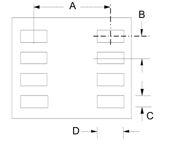
Recommended
Land Patterns
| SERIES | DIMENSION S mm/in | |||
| A | B | C | D | |
| 741X043 | 1.00 | 0.65 | 0.33 | 0.50 |
| 0.039 | 0.026 | 0.013 | 0.020 | |
| 741X083 | 1.00 | 0.50 | 0.30 | 0.50 |
| 0.039 | 0.020 | 0.012 | 0.020 | |
| 741C083 | 1.00 | 0.50 | 0.28 | 0.50 |
| 0.039 | 0.020 | 0.011 | 0.020 | |
| 741X163 | 1.60 | 0.50 | 0.30 | 0.80 |
| 0.063 | 0.020 | 0.012 | 0.031 | |
| 742 | 1.60 | 0.80 | 0.50 | 0.90 |
| 0.063 | 0.032 | 0.020 | 0.035 | |
| 743 | 2.00 | 1.27 | 0.80 | 1.00 |
| 0.079 | 0.050 | 0.031 | 0.051 | |
| 744 | 3.20 | 1.27 | 0.80 | 1.00 |
| 0.126 | 0.050 | 0.031 | 0.039 | |
| 745 | 3.20 | 1.27 | 0.90 | 1.30 |
| 0.126 | 0.050 | 0.035 | 0.039 | |
| 746 | 1.65 | 0.64 | 0.35 | 0.80 |
| 0.065 | 0.025 | 0.014 | 0.032 | |
A
Environmental Performance Spec
ifications
| Test | Max. Delta R | Test Description | |
|---|---|---|---|
| 741 | 742-746 | ||
| Thermal Cycle | 1.00% | 1.00% | 5 Cycles -55°C to +125°C |
| Short Time Overload | 2.50% | 1.00% | 2½ X Rated Working Voltage for 5 Seconds |
| Moisture Resistance | 5.00% | 2.00% | 240 Hours 10% rated load, -10°C to +65°C, 90% R.H. |
| High Temperature Exposure | 1.00% | 1.00% | 1000 Hours, no load, +125°C |
| Load Life | 5.00% | 2.00% | 1000 Hours @ 70°C, rated load |
| Resistance to Solder Heat | 2.50% | 1.00% | 10 Seconds @ 260°C solder |
| Resistance to Solvents | Isopropyl alcohol, Freon TMC | ||
| Solderability | RMA Flux, 230°C, 5 Seconds dip, 95% coverage | ||
May 2006
Page 4 of 5
Page 5
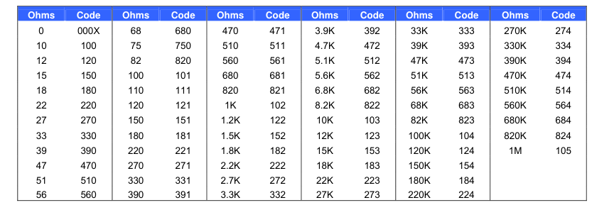
StandardResistor Values &EIACod
e
How to Order
742C083 101 J P
Part Code
See Standard Package Outlines (Page 2)
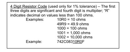
Resistor Code
3 Digit Resistor Code – Refer to the EIA Code noted above
RoHS Compliant (matte Sn finis
h)
Insert “P” for RoHS; Otherwise blank
Tolerance
J = ±5% (Standard) 3-digit code G = ±2% 3-digit code (741-745 only) F = ±1% 4-digit code(741-745 only) X for zero ohm jumper
| Part Marking | J & G tol. | F tol. | |
|---|---|---|---|
| E-24 Value | E-24 Value | E-96 Value | |
| 741 | 3 Digit | 3 Digit | 4 Digit |
| 742 | 3 Digit | 3 Digit | 4 Digit |
| 743 | 3 Digit | 4 Digit | 4 Digit |
| 744 | 3 Digit | 4 Digit | 4 Digit |
| 745 | 3 Digit | 4 Digit | 4 Digit |
| 746 | 3 Digit | 4 Digit | 4 Digit |
Tape & Reel Information
| Reel Diameter 7" | 741X043 741C083 741X083 | 742C043 741X163 | 742C083 742X083 | 742C163 | 743C043 | 743C083 | 744C043 | 744C083 | 745C101 745C102 | 745X101 745X102 | 746X101 |
| Parts/Reel | 10000 | 5000 | 5000 | 4000 | 4000 | 4000 | 4000 | 2000 | 4000 | 4000 | 5000 |
| Pitch | 2mm | 4mm | 4mm | 4mm | 4mm | 4mm | 4mm | 8mm | 4mm | 4mm | 4mm |
| Carrier Width | 8mm | 8mm | 8mm | 12mm | 8mm | 12mm | 8mm | 12mm | 12mm | 12mm | 8mm |
| Material | Paper | Paper | Paper | Plastic | Plastic | Plastic | Plastic | Plastic | Plastic | Plastic | Paper |
May 2006
Page 5 of 5