

 Download PDF
700-SC ALLEN-BRADLEY
Document overview
- PDF pages: 5
Technical content
Page 1
Overview/Product Selection
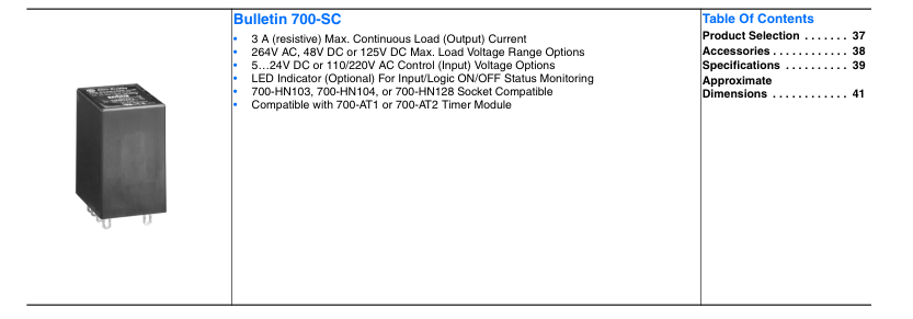
Product Selection
| Input-to-Output Isolation Method | Zero Cross Function | LED Indicator | Rated Output (Load) Max. Current and Voltage Range | Rated Input Control Voltage | Cat. No. | Factory- stocked Item (Single Pack) | |
|---|---|---|---|---|---|---|---|
| Photocoupler | Yes | Yes | 3 A @100…240V AC | 5…24V DC | 700-SCZY3Z25 | ✔ | |
| 2 A @ 100…240V AC | 100/110V AC | 700-SCZY2A1 | ✔ | ||||
| 200/220V AC | 700-SCZY2A2 | ✔ | |||||
| Phototriac | No | 3 A @100…240V AC | 24V DC | 700-SCTY3Z24 | ✔ | ||
| Photocoupler | No | 3 A @ 4…48V DC | 5…24V DC | 700-SCNY3Z25 | ✔ | ||
| Yes | No | 3 A @ 100…240V AC | 4…24V DC | 700-SCZN3Z26 | ✔ | ||
| Phototriac | No | 24V DC | 700-SCTN3Z24 | ✔ | |||
| Photocoupler | N/A | 3 A @ 4…48V DC | 4…24V DC | 700-SCNN3Z26 | ✔ | ||
| 2 A @ 5…110V DC | 5…24V DC | 700-SCNN2Z25 | ✔ |
Page 2
Accessories
| Description | Pkg. Quantity | Cat. No. | Factory-stocked Item | |
|---|---|---|---|---|
| Cat. No. 700-HN103 | Screw Terminal Socket — Panel or DIN Rail Mounting; Guarded Terminal Construction Order must be in ten or multiples of ten | 1 | 700-HN103 | ✔ |
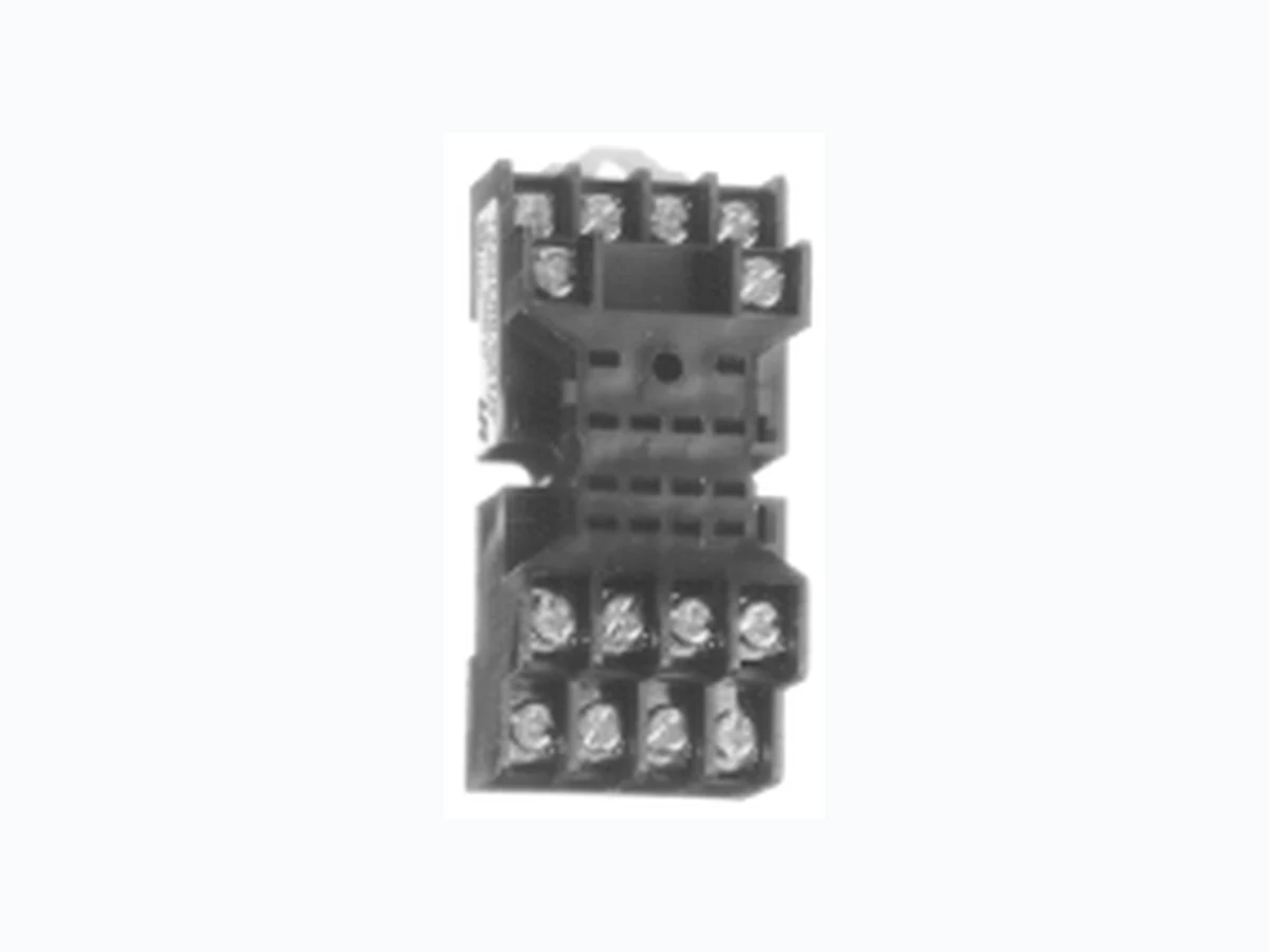
| Cat. No. 700-HN104 | Screw Terminal Socket – Panel or DIN Rail Mounting. Guarded Terminal Construction 14-blade miniature socket for use with Bulletin 700-SC relays. This socket has coil and contact separation as well as the ability to plug in optional plug in modules (700-A** accessories: LED, Surge Suppression, Timing Modules) | 10 | 700-HN104 | ✔ |
| Cat. No. 700-HN128 | Screw Terminal Base Socket — Panel or DIN Rail Mounting; Open Style Construction Order must be in multiples of ten | 10 | 700-HN128 | ✔ |
| Cat No. 199-DR1 | DIN Rail Mounting Pack Standard 35 x 7.5 mm DIN Rail, 1 meter long, 10 rails per package. Order must be for 10 rails or multiples of 10. | 10 | 199-DR1 | ✔ |
| Pre-printed identification tags — contains 10 sheets of pre-printed and blank tags. Each sheet contains 13 sets of the markings CR…9CR, TR…9TR, M…9M, F, R, 1S, and 117 blank tags. Tags are peel-off with sticky backing for easy placement on relays. | 10 | 700-N40 | ||
| Blank identification tags — contains 10 sheets of blank identification tags for customer specialized printing. Each sheet contains 546 blank tags. Tags are peel-off with sticky backing for easy placement on relays. | 10 | 700-N41 | ||
| Sample Retainer Clips | Retainer Clip Secures relay in socket. Order must be for 10 clips or multiples of 10. | 10 | 700-HN114(B)➊ | ✔ |
| ON-Delay Time Module Voltage Range: 12…24V AC/DC used with 700-HN153 socket | 1 | 700-AT1 | ||
| One Shot Timing Module Voltage Range: 12…24V AC/DC used with 700-HN153 socket | 1 | 700-AT2 |
➊ Series B retainer clip must be used with Bulletin 700-SC
Page 3
Specifications
Control/Input Ratings
| Cat. No. | Rated Control Voltage | Operating Control Voltage Range | Impedance | Control Voltage Levels | |
| Pick-up Voltage | Drop-out Voltage | ||||
| 700-SCZY3Z25 | 5…24V DC | 4…28V DC | 15 mA max. ➊ | 4V DC max. | 1V DC min. |
| 700-SCZY2A1 | 100/110V AC | 75…125V AC | 41 KΩ± 20% | 75V AC max. | 20V AC min. |
| 700-SCZY2A2 | 200/220V AC | 150…250V AC | 72 KΩ ± 20% | 150V AC max. | 40V AC min. |
| 700-SCTY3Z24 | 24V DC | 19.2…28.8V DC | 2 KΩ ± 20% | 19.2V DC max. | 1V DC min. |
| 700-SCNY3Z25 | 5…24V DC | 4…28V DC | 1.5 KΩ + 20%/–10% ➋ | 4V DC max. | |
| 700-SCZN3Z26 | 4…24V DC | 3…28V DC | 15 mA max. ➊ | 3V DC max. | |
| 700-SCTN3Z24 | 24V DC | 19.2…28.8V DC | 2 kΩ ± 20% | 19.2V DC max. | |
| 700-SCNN3Z26 | 4…24V DC | 3…28V DC | 1.5 KΩ + 20%/–10% ➋ | 3V DC max. | |
| 700-SCNN2Z25 | 5…24V DC | ||||
Load/Output Ratings
| Cat. No. | Rated Load Voltage | Applicable Load | |||
| Load Voltage Range | Continuous Load Current (Resistive) | Max. Inrush Current ➌ | |||
| — | — | — | Min. | Max. ➍ | — |
| 700-SCZY3Z25 | 100…240V AC | 75…264V AC | 0.1 A | 3 A | 45 A (@50/60 Hz, 1 cycle) |
| 700-SCTY3Z24 | |||||
| 700-SCZN3Z26 | |||||
| 700-SCTN3Z24 | |||||
| 700-SCZY2A1 | 100…240V AC | 0.1 A | 2 A | ||
| 700-SCZY2A2 | |||||
| 700-SCNN3Z25 | 4…48V DC | 3…52.8V DC | 0.1 A | 3 A | 18 A (10 ms) |
| 700-SCNY3Z26 | |||||
| 700-SCNN2Z25 | 5…110V DC | 3…125V DC | 0.1 A | 2 A | 10 A (10 ms) |
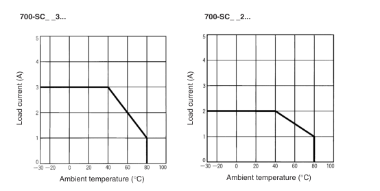
➊ With constant current input circuit system. SSR impedance varies with a change in input voltage. ➋ Input impedance attains its maximum at the operating voltage. ➌ If the SSR operation is continuous ON/OFF, this value should be reduced by 50%. Refer to “Inrush Current Resistivity” graphs on page 40 for details. ➍ Refer to the following "Load Current Versus Ambient Temperature Characteristics" graphs on page 40 for additional load current details.
Characteristics
| Cat. No. | 700-SCZ…. | 700-SCT | 700-SCNN3… | 700-SCNN2… |
| Load Switching Method/Device | Triac | Transistor | ||
| Pick-up Time | 1/2 of load power source + 1 ms max. (DC input) | 1 ms max | 0.5 ms max | 0.5 ms max |
| 3/2 of load power source + 1 ms max. (AC input) | ||||
| Drop-out Time | 1/2 of load power source + 1 ms max. (DC input) | 1/2 of load power source + 1 ms max | 2 ms max | 2.5 ms max |
| 3/2 of load power source + 1 ms max. (AC input) | ||||
| Output ON Voltage Drop | 1.6 V (RMS) max | 1.6V (RMS) | 1.5 V max. | 1.5V max. |
| Output Leakage Current | 5 mA max (@ 100 V AC) 10 mA max (@ 200 V AC) | 2.5 mA max (@ 100 V AC) 5 mA max (at 200 V AC) | 5 mA max (@ 50 V DC) | 0.1 mA max (@ 100 V DC) |
| Output VDRM, VCEO (V) | 600 | 600 | 80 | 80 |
| Output di/dt (A/uS) | 50 | 50 | — | — |
| Output dv/dt (V/uS) | 250 | 250 | — | — |
| Output I2t (A2S) | 18 | 18 | — | — |
| Output Tj °C Max. | 125 | 125 | 150 | 150 |
| Insulation Resistance | 100 MΩ min (@ 500V DC) | |||
| Dielectric Strength | 1,500 V AC, 50/60 Hz for 1 minute | |||
| Vibration Resistance (max.) | 10…55 Hz, 1.5 mm double amplitude (10 G) | |||
| Shock Resistance (max.) | 1,000 m/s2 (100 G) | |||
| Ambient Temperature | Operating: -30°C…80°C (-22...176°F) with no icing or condensation Storage: -30°C…100°C (-22...212°F) with no icing or condensation | |||
Page 4
Specifications, Continued
Characteristics
| Standards | UL508, CSA C 22.2, CE, VDE |
| Ambient Humidity | Operating: 45%…85% (no condensation) |
| Weight | Approx. 50 g |
Load Current Versus Ambient Temperature Characteristics
Inrush Current Resistivity➊
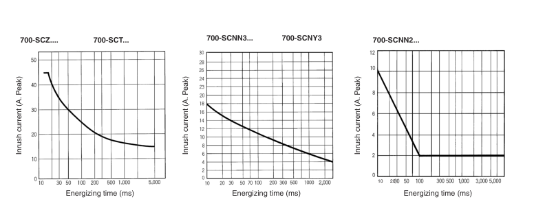
➊ Inrush current resistivity is the ability of an SSR to withstand a large surge current for a short period of time. Surges are considered non-repetitive (max. repeatability once every 2…5 seconds). Keep the inrush current to half the rated value if it occurs repetitively. Exceeding the non-repetitive inrush current will damage the SSR.
Page 5
Approximate Dimensions
Note: Bulletin 700-SC is compatible with the 700-HN103, 700-HN104, and 700-HN128 sockets. All units in millimeters unless otherwise indicated. Dimensions are not intended for manufacturing purposes.
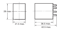
Cat, No 700-SC… ➊
➊ Bulletin 700-SC is compatible with cat. nos. 700-HN103, -HN104, and -HN128 socket.
Basic Application Considerations For Bulletin 700-SC
Connection
Terminal Arrangement/ Internal Connections (Bottom View)
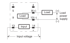
Note: The plus and minus symbols shown in parentheses are for DC loads.
For DC Load Switching, Bulletin 700-SC will operate properly if the load is connected to either the positive or negative SSR load terminal.
High-density Mounting of Multiple SSRs If multiple relays are mounted side by side, be aware that the outer wall of each SSR works as a radiator. The SSR casing serves to dissipate heat. Install the relays so that they are adequately ventilated. If poor ventilation is unavoidable, reduce the load current by half.
Protective Component When controlling AC inductive loads, connect an inrush/surge absorbing device (varistor) across the SSR load terminals. If the SSR has built-in surge suppression (Bulletins 700-SE and 700-SH) and additional surge suppression is required, connect the varistor across the terminals of the load device . Select a varistor that meets the conditions of the load voltage outlined in the table below. Note: For additional details applying solid-state relays, refer to pub. number 700-AT001A-EN-E, "Solid-State Relay Application Guide." Document available at www.theautomationbookstore.com.
| Load Voltage | Varistor Voltage | Varistor Surge Resistance |
| 100…120V AC | 240…270 V | 1000 A min. |
| 200…240V AC | 440…470 V | |
| 380…480V AC | 820…1000 V |