


 Download PDF
L208 IXYS
Document overview
- PDF pages: 2
Technical content
Page 1
DSS 6-0045AS
Power Schottky Rectifier
IFAV
= 6 A
VRRM = 45 V
VF = 0.5 V
TO-252 AA
VRSM
VRRM
Type
marking
A
C
V V
on product
A
45 45
DSS 6-0045AS
6Y045AS
A C (TAB)
A = Anode, C = Cathode , TAB = Cathode
Symbol
Conditions
Maximum Ratings
Features
- International standard package
IFRMS
20 A
- Very low VF
TC = 165°C; rectangular, d = 0.5 6 A
IFAV
IFSM
TVJ = 45°C; tp = 10 ms (50 Hz), sine
EAS
IAS = 13 A; L = 180 µH; TVJ = 25°C; non repetitive
IAR
VA =1.5 • VRRM typ.; f=10 kHz; repetitive
(dv/dt)cr
TVJ
TVJM
Tstg
TC = 25°C
Ptot
Weight
typical
Symbol
Conditions
- Extremely low switching losses
- Low IRM-values
80 A
- Epoxy meets UL 94V-0
24 mJ
1.3 A
Applications
- Rectifiers in switch mode power
V/µs 1000
supplies (SMPS) °C
-55...+175
- Free wheeling diode in low voltage
°C 175
converters °C
-55...+150
50 W Advantages
- High reliability circuit operation
0.3 g
- Low voltage peaks for reduced protection circuits
- Low noise switching
Characteristic Values
- Low losses
| typ. | max. |
|---|---|
| I c T = 25°C V = V R VJ R RRM T = 125°C V = V VJ R RRM | 0.3 mA 2.5 mA |
| V I = 6 A; T = 125°C F F VJ I = 6 A; T = 25°C F VJ I = 12 A; T = 125°C F VJ | 0.50 V 0.63 V 0.59 V |
| R thJC | 3.0 K/W |
Pulse test: c Pulse Width = 5 ms, Duty Cycle < 2.0 % Data according to IEC 60747 and per diode unless otherwise specified
IXYS reserves the right to change limits, Conditions and dimensions.
1 - 2
Dimensions see Outlines.pdf
© 2003 IXYS All rights reserved
Page 2
DSS 6-0045AS
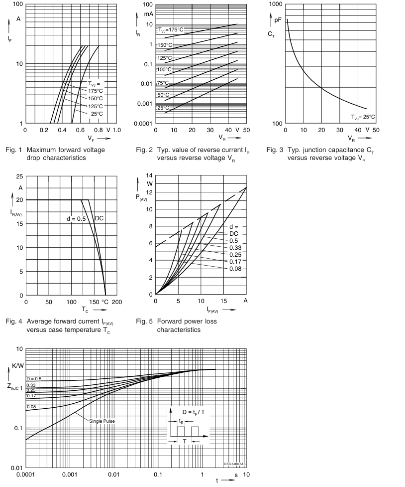
Fig. 6 Transient thermal impedance junction to case at various duty cycles
Note: All curves are per diode
© 2003 IXYS All rights reserved 2 - 2