
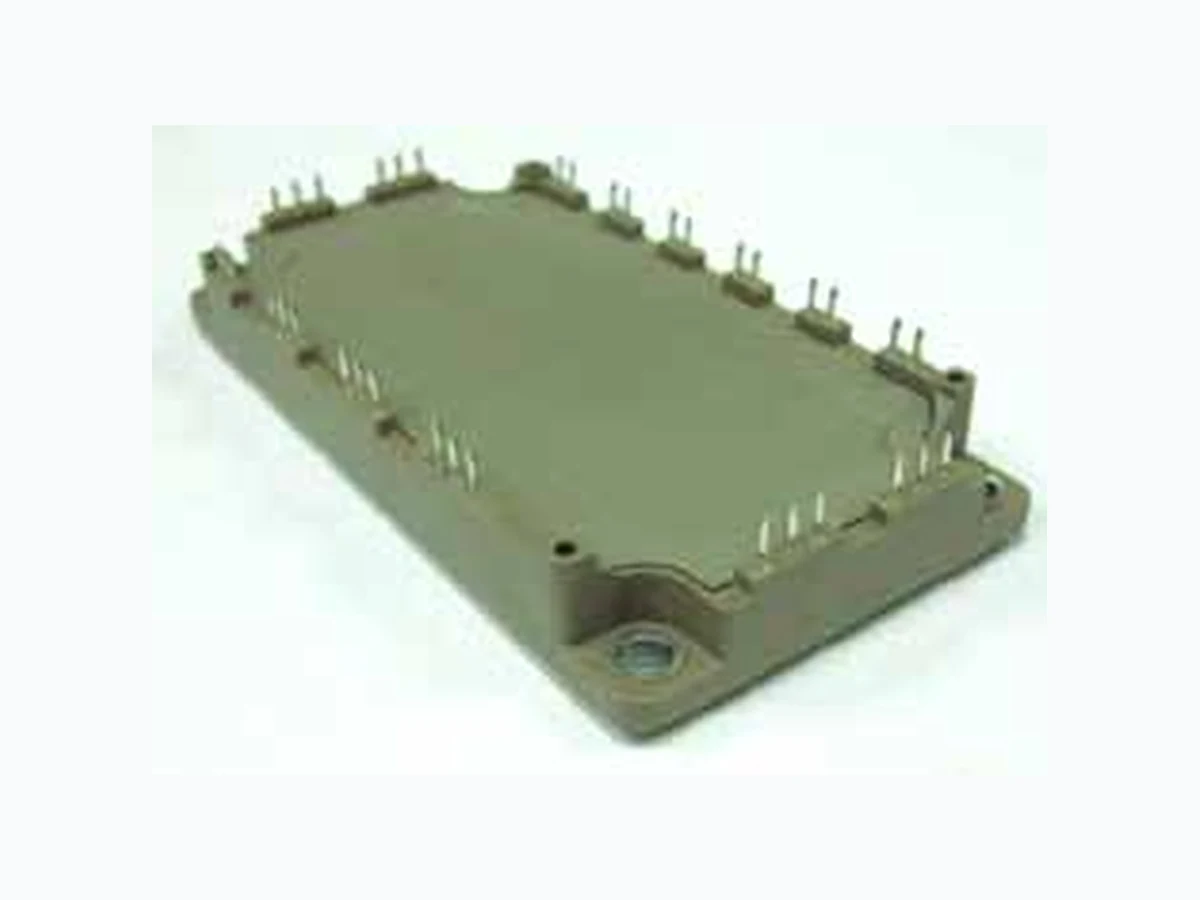
6MBI100VB-120-50 FUJI
Document overview
- Manufacturer or author: Provided By digicamel.com
- PDF pages: 6
Technical content
Features
P.C.Board Mount Low VCE (sat)
Applications
AC and DC Servo Drive Amplifier Uninterruptible Power Supply Industrial machines, such as welding machines Maximum Ratings and Characteristics Absolute Maximum Ratings (at Tc=25 °C unless otherwise specified) Items Symbols Conditions Maximum ratings Units Inverter Collector-Emitter voltage VCES 1200 V Gate-Emitter voltage VGES ±20 V Collector current Ic Continuous Tc=80°C 100 AIc pulse 1ms Tc=80°C 200 -Ic 100 -Ic pulse 1ms 200 Collector power dissipation Pc 1 device 520 W Junction temperature Tj 175 Operating junciton temperature (under switching conditions) Tjop 150 Case temperature Tc 125 Storage temperature Tstg -40 ~ +125 Isolation voltage Between terminal and copper base (*1) Between thermistor and others (*2) Viso AC : 1min. 2500 VAC Screw torque Mounting (*3) - M5 3.5 N m Note *1: All terminals should be connected together during the test. Note *2: Two thermistor terminals should be connected together, other terminals should be connected together and shorted to base plate during the test. Note *3: Recommendable value : 2.5-3.5 Nm (M5)
http://www.fujielectric.com/products/semiconductor/ IGBT Modules Electrical characteristics (at Tj= 25°C unless otherwise specified) Items Symbols Conditions Characteristics Unitsmin. typ. max. Inverter Zero gate voltage collector current ICES VGE = 0V, VCE = 1200V - - 1.0 mA Gate-Emitter leakage current IGES VCE = 0V, VGE = ±20V - - 200 nA Gate-Emitter threshold voltage VGE (th) VCE = 20V, IC = 100mA 6.0 6.5 7.0 V Collector-Emitter saturation voltage VCE (sat) (terminal) VGE = 15V IC = 100A V Tj=125°C - 2.60 - Tj=150°C - 2.65 - VCE (sat) (chip) VGE = 15V IC = 100A Tj=125°C - 2.05 - Tj=150°C - 2.10 - Input capacitance Cies VCE = 10V, VGE = 0V, f = 1MHz - 9.1 - nF Turn-on time ton VCC = 600V IC = 100A VGE = +15 / -15V RG = 1.6Ω - 0.39 1.20 µs tr - 0.09 0.60 tr (i) - 0.03 - Turn-off time toff - 0.53 1.00 tf - 0.06 0.30 Forward on voltage VF (terminal) IF = 100A V Tj=125°C - 2.40 - Tj=150°C - 2.35 - VF (chip) IF = 100A Tj=125°C - 1.85 - Tj=150°C - 1.80 - Reverse recovery time trr IF = 100A - - 0.35 µs Thermistor Resistance R T = 25°C - 5000 - ΩT = 100°C 465 495 520 B value B T = 25 / 50°C 3305 3375 3450 K Thermal resistance characteristics Items Symbols Conditions Characteristics Unitsmin. typ. max. Thermal resistance (1device) Rth(j-c) Inverter IGBT - - 0.29 °C/WInverter FWD - - 0.44 Contact thermal resistance (1device) (*4) Rth(c-f) with Thermal Compound - 0.05 - Note *4: This is the value which is defined mounting on the additional cooling fin with thermal compound. Equivalent Circuit Schematic [ Thermistor ] [ Inverter ] U V W 13,14,15 16,17,18 21,22,23 24,25,26 19 20 27,28,29 30,31,32 33,34,35
http://www.fujielectric.com/products/semiconductor/ 6MBI100VB-120-50 Characteristics (Representative) [ Inverter ] Tj= 150 o C / chip Collector current vs. Collector-Emitter voltage (typ.) Collector-Emitter voltage: VCE [V] Collector current : IC [A] Collector-Emitter voltage: VCE [V] Capacitance: Cies, Coes, Cres [nF] Gate charge: Qg [nC] [ Inverter ] Collector current vs. Collector-Emitter voltage (typ.) Tj= 25 o C / chip Collector-Emitter voltage: VCE [V] Collector current : IC [A] VGE=15V / chip [ Inverter ] Collector current vs. Collector-Emitter voltage (typ.) Collector current : IC [A] Collector - Emitter voltage : VCE [V] Gate - Emitter voltage: VGE [V] [ Inverter ] Tj= 25 o C / chip Collector-Emitter voltage vs. Gate-Emitter voltage (typ.) Collector - Emitter voltage: VCE [V] [ Inverter ] Dynamic gate charge (typ.) Vcc=600V , Ic=100A , Tj= 25°C Collector - Emitter voltage: VCE [200V/div] Gate - Emitter voltage: VGE [5V/div] Capacitance vs. Collector-Emitter voltage (typ.) V GE =0V, f= 1MHz, Tj= 25 o C [ Inverter ] 100 150 200 0 1 2 3 4 5 VGE=20V 15V 12V 10V 100 150 200 0 1 2 3 4 5 15V 12V 10V VGE=20V 100 150 200 0 1 2 3 4 5 125°C Tj=25°C 150°C 5 10 15 20 25 Ic=200A Ic=100A Ic= 50A 0.1 1.0 10.0 100.0 0 10 20 30 40 Cies Coes Cres 0 250 500 750 1000 V GE V CE
http://www.fujielectric.com/products/semiconductor/ IGBT Modules Gate resistance : RG [Ω] [ Inverter ] Reverse bias safe operating area (max.) +VGE=15V,-VGE <= 15V, RG >= 1.6Ω ,Tj <= 125°C C o l l e c t o r c u r r e n t : I C [A] Collector current: I C [A] [ Inverter ] Vcc=600V, VGE=±15V, RG=1.6Ω Switching loss vs. Collector current (typ.) S w i t c h i n g t i m e : t o n , t r , t o f f , t f [ n s e c ] S w i t c h i n g t i m e : t o n , t r , t o f f , t f [ n s e c ] S w i t c h i n g l o s s : E o n , E o f f , E r r [ m J / p u l s e ] [ Inverter ] Switching time vs. Collector current (typ.) Vcc=600V, VGE=±15V, RG=1.6Ω, Tj= 125°C Gate resistance : RG [Ω] S w i t c h i n g l o s s : E o n , E o f f , E r r [ m J / p u l s e ] Collector-Emitter voltage : V CE [V] [ Inverter ] Switching loss vs. gate resistance (typ.) Vcc=600V, Ic=100A, VGE=±15V [ Inverter ] Switching time vs. gate resistance (typ.) Vcc=600V, Ic=100A, VGE=±15V, Tj= 125°C S w i t c h i n g t i m e : t o n , t r , t o f f , t f [ n s e c ] Collector current: I C [A] [ Inverter ] Vcc=600V, VGE=±15V, RG=1.6Ω, Tj= 150°C Switching time vs. Collector current (typ.) Collector current: I C [A] 100 150 200 250 0 200 400 600 800 1000 1200 1400 1600 RBSOA (Repetitive pulse) 100 1000 10000 0 50 100 150 200 250 toff 100 1000 10000 0 50 100 150 200 250 toff 100 1000 10000 0.1 1.0 10.0 100.0 tr tf toff ton 0 50 100 150 200 250 Eon(125°C) Eon(150°C) Eoff(125°C) Err(125°C) Err(150°C) Eoff(150°C) 0 1 10 100 Eon(125°C) Eon(150°C) Eoff(125°C) Err(125°C) Err(150°C) Eoff(150°C) ton tr tf ton tr tf
http://www.fujielectric.com/products/semiconductor/ 6MBI100VB-120-50 F o r w a r d c u r r e n t : I F [ A ] R e v e r s e r e c o v e r y c u r r e n t : I r r [ A ] R e v e r s e r e c o v e r y t i m e : t r r [ n s e c ] [ Thermistor ] Temperature characteristic (typ.) Transient thermal resistance (max.) [ Inverter ] Reverse recovery characteristics (typ.) [ Inverter ] Forward current vs. forward on voltage (typ.) chip Vcc=600V, VGE=±15V, RG=1.6Ω Forward on voltage : V F [V] Forward current : I F [A] Temperature [°C ] R e s i s t a n c e : R [ k Ω ] Pulse width : Pw [sec] T h e r m a l r e s i s t a n s e : R t h ( j - c ) [ ° C / W ] 0.01 0.10 1.00 10.00 0.001 0.010 0.100 1.000 FWD[Inverter] IGBT[Inverter] 0.1 100 -60 -40 -20 0 20 40 60 80 100 120 140 160 180 100 150 200 0 1 2 3 4 Tj=125°C Tj=25°C 100 1000 0 50 100 150 200 250 trr(150°C) Tj=150°C Irr(125°C) Irr(150°C) trr(125°C) Outline Drawings, mm
http://www.fujielectric.com/products/semiconductor/ IGBT Modules WARNING 1. This Catalog contains the product specifications, characteristics, data, materials, and structures as of May 2011. The contents are subject to change without notice for specification changes or other reasons. When using a product listed in this Catalog, be sur to obtain the latest specifications. 2. All applications described in this Catalog exemplify the use of Fuji's products for your reference only. No right or license, either express or implied, under any patent, copyright, trade secret or other intellectual property right owned by Fuji Electric Co., Ltd. is (or shall be deemed) granted. Fuji Electric Co., Ltd. makes no representation or warranty, whether express or implied, relating to the infringement or alleged infringement of other's intellectual property rights which may arise from the use of the applications described herein. 3. Although Fuji Electric Co., Ltd. is enhancing product quality and reliability, a small percentage of semiconductor products may become faulty. When using Fuji Electric semiconductor products in your equipment, you are requested to take adequate safety measures to prevent the equipment from causing a physical injury, fire, or other problem if any of the products become faulty. It is recommended to make your design failsafe, flame retardant, and free of malfunction. 4. The products introduced in this Catalog are intended for use in the following electronic and electrical equipment which has normal reliability requirements.
- Computers • OA equipment • Communications equipment (terminal devices) • Measurement equipment
- Machine tools • Audiovisual equipment • Electrical home appliances • Personal equipment • Industrial robots etc. 5. If you need to use a product in this Catalog for equipment requiring higher reliability than normal, such as for the equipment listed below, it is imperative to contact Fuji Electric Co., Ltd. to obtain prior approval. When using these products for such equipment, take adequate measures such as a backup system to prevent the equipment from malfunctioning even if a Fuji's product incorporated in the equipment becomes faulty.
- Transportation equipment (mounted on cars and ships) • Trunk communications equipment
- Traffic-signal control equipment • Gas leakage detectors with an auto-shut-off feature
- Emergency equipment for responding to disasters and anti-burglary devices • Safety devices
- Medical equipment 6. Do not use products in this Catalog for the equipment requiring strict reliability such as the following and equivalents to strategic equipment (without limitation).
- Space equipment • Aeronautic equipment • Nuclear control equipment
- Submarine repeater equipment 7. Copyright ©1996-2011 by Fuji Electric Co., Ltd. All rights reserved. No part of this Catalog may be reproduced in any form or by any means without the express permission of Fuji Electric Co., Ltd. 8. If you have any question about any portion in this Catalog, ask Fuji Electric Co., Ltd. or its sales agents before using the product. Neither Fuji Electric Co., Ltd. nor its agents shall be liable for any injury caused by any use of the products not in accordance with instructions set forth herein.