


 Download PDF
6A05 JINANJINGHENG
Document overview
- PDF pages: 2
Technical content
Page 1
R
S E M I C O N D U C T O R
FEATURES
The plastic package carries Underwrites Laboratory Flammability Classification 94V-0 High forward current capability High surge current capability Construction utilizes void-free molded plastic technique
High temperature soldering guaranteed:260 C/10 seconds at terminals 0.375"(9.5mm) lead length, 5 lbs, (2.3kg) tension Component in accordance to RoHs 2002/95/EC and WEEE 2002/96/EC
MECHANICAL DATA
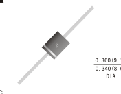
Case: R-6 molded plastic body Terminals: Plated axial lead, solderable per MIL-STD-750,method 2026 Polarity: Color band denotes cathode end Mounting Position: Any Weight: 0.07ounce, 2.1 grams
6A05 THRU 6A10
GENERAL PURPOSE PLASTIC RECTIFIER
Reverse Voltage - 50 to 1000 Volts
Forward Current -6.0Amperes
R-6
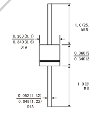
1.0(25.4)
Dimensions in inches and (millimeters)
MAXIMUM RATINGS AND ELECTRICAL CHARACTERISTICS
(Ratings at 25 C ambient temperature unless otherwise specified ,Single phase ,half wave 60Hz,,resistive or inductive
load. For capacitive load, derate by 20%.)
| Symbols | 6A05 | 6A1 | 6A2 | 6A3 | 6A4 | 6A6 | 6A8 | 6A10 | Unis | |||
|---|---|---|---|---|---|---|---|---|---|---|---|---|
| Maximum recurrent peak reverse voltage | VRRM | 50 | 100 | 200 | 300 | 400 | 600 | 800 | 1000 | Volts | ||
| Maximum RMS voltage | VRMS | 35 | 70 | 140 | 210 | 280 | 420 | 560 | 700 | Volts | ||
| Maximum DC blocking voltage | VDC | 50 | 100 | 200 | 300 | 400 | 600 | 800 | 1000 | Volts | ||
| Maximum average forward rectified current 0.375"(9.5mm) lead length TA=60 C | I(AV) | 6 | .0 | Amps | ||||||||
| Peak forward surge current (8.3ms half sine- wave superimposed on rated load (JEDEC method) | IFSM | 250 | .0 | Amps | ||||||||
| Maximum instantaneous forward voltage at 6.0 A | VF | 0. | 95 | Volts | ||||||||
| Maximum reverse current at rated DC blocking voltage | TA =25 C | IR | 10 | .0 | A | |||||||
| TA =100 C | 40 | 0.0 | ||||||||||
| Maximum Full Load Reverse Current,Full Cycle Average .375"(9.5mm)Lead Length @TA=75°C | HTIR | 5. | 0 | A | ||||||||
| Typical thermal resistance (Note 2) Typical junction capacitance (Note 1) | R JA CJ | C/W | ||||||||||
| 35 | .0 | |||||||||||
| 90 | PF | |||||||||||
| Operating and Storage temperature range | TJ TSTG | -65 to+150 C | ||||||||||
Note: 1.Measured at 1MHz and applied reverse voltage of 4.0V D.C .
2.Mounton Cu-Pad Size 16mm×16mm on P.C.B.
6-38
JINAN JINGHENG CO., LTD. NO.51 HEPING ROAD JINAN P.R. CHINA TEL:86-531-86943657 FAX:86-531-86947096
WWW.JIFUSEMICON.COM
Page 2
RATINGS AND CHARACTERISTIC CURVES 6A05 THRU 6A10
FIG.1-FORWARD CURRENT DERATING CURVE
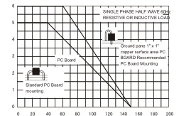
AMBIENT TEMPERATURE ( C)
FIG.3-MAXIMUM NON-REPETITIVE PEAK
FORWARD SURGE CURRENT
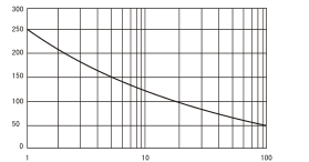
NUMBER OF CYCLES AT 60Hz
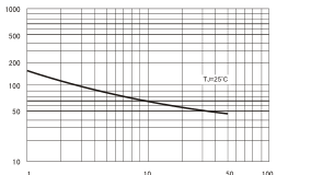
FIG.5-TYPICAL JUNCTION CAPACITANCE
1
10
50 100
REVERSE VOLTAGE.(V)
FIG.2-TYPICAL INSTANTANEOUS FORWARD
CHARACTERISTICS
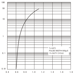
INSTANTANEOUS FORWARD VOLTAGE (VOLTS)
FIG.4-TYPICAL REVERSE CHARACTERISTICS
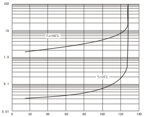
PERCENT OF RATED PEAK REVERSE VOLTAGE %
6-39