
DATASHEET SEARCH SITE
Document overview
- Manufacturer or author: Provided By www.digicamel.com(FREE DATASHEET DOWNLOAD SITE)
- PDF pages: 14
Technical content
Features
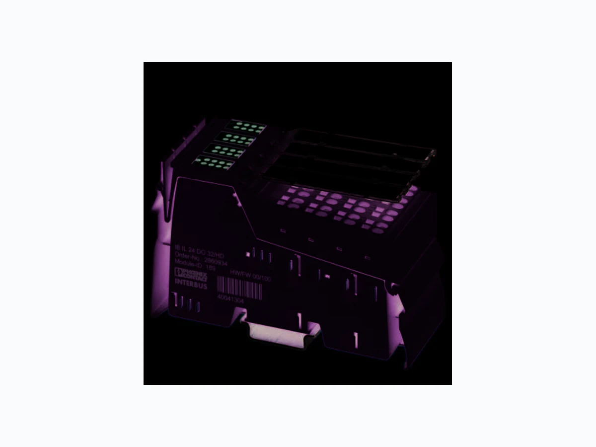
– 32 digital outputs – Connection of actuators in single-wire technology – Nominal current per output: 500 mA – Total current of the terminal: 8 A – Short-circuit-proof and ov erload-protected outputs IB IL 24 DO 32/HD-PAC WARNING: Explosion hazard when used in potentially explosive areas When using the terminal in potentially explosive areas, observe the corresponding notes. This data sheet is only valid in association with the IL SYS INST UM E user manual. Make sure you always use the latest documentation. It can be downloaded from the product at phoenixcontact.net/products. 6843_en_06 2017-08-01
IB IL 24 DO 32/HD (2MBD)-PAC 6843_en_06 PHOENIX CONTACT 2 / 14 2T a b l e o f c o n t e n t s
IB IL 24 DO 32/HD (2MBD)-PAC 6843_en_06 PHOENIX CONTACT 3 / 14 Description Ty pe Order No. Pcs./Pkt. Inline, Digital output terminal, Digital outputs: 32, 24 V DC, 500 mA, connection method: 1-wire, transmission speed in the local bus 500 kbps, degree of protection IP20, including Inline connectors and marking fields IB IL 24 DO 32/HD-PAC 2862822 1 Inline, Digital output terminal, Digital outputs: 32, 24 V DC, 500 mA, connection method: 1-wire, transmission speed in the local bus 2 Mbps, degree of protection IP20, including Inline connectors and marking fields IB IL 24 DO 32/HD-2MBD- PAC 2692898 1 3O r d e r i n g d a t a Accessories Ty pe Order No. Pcs./Pkt. Inline terminal for power distribution (GND), complete with accessories, (connector and labeling field) connections for GND IB IL PD GND-PAC 2862990 1 Connector set IB IL DI/DO 8-PLSET 2860950 1 Labeling field, width: 12.2 mm (Marking) IB IL FIELD 2 2727501 10 Labeling field, width: 48.8 mm (Marking) IB IL FIELD 8 2727515 10 Insert strip, Sheet, white, unlabeled, can be labeled with: Office printing systems: Laser printer, Mounting type: Insert, Lettering field: 62 x 10 mm (Marking) ESL 62X10 0809492 1 Insert strip, Sheet, white, unlabeled, can be labeled with: Office printing systems: Laser printer, Mounting type: Insert, Lettering field: 62 x 46 mm (Marking) ESL 62X46 0809502 5 VARIOFACE front adapter for Inline modules, for transferring 32 (4 x 8) digital signals. (Connector/Adapter) FLKM 14-PA-INLINE/32 2302777 1 Documentation Ty pe Order No. Pcs./Pkt. User manual, English, Automation terminals of the Inline product range IL SYS INST UM E - - Data sheet, English, INTERBUS addressing DB GB IBS SYS ADDRESS - - Application note, addressing of 16-channel Inline terminals AH IB IL 24 DI/DO 16 ADDRESS Application note, English, Inline terminals for use in zone 2 potentially explosive areas AH EN IL EX ZONE 2 - -
IB IL 24 DO 32/HD (2MBD)-PAC 6843_en_06 PHOENIX CONTACT 4 / 14 Dimensions (nominal sizes in mm) Width 48.8 mm Height 119.8 mm Depth 71.5 mm Note on dimensions Housing dimensions
4 Technical data
119,8 71,5 General data Color green Weight 195 g (with connectors) Operating mode Process data operation with 2 words Ambient temperature (operation) -25 °C ... 55 °C Ambient temperature (storage/transport) -25 °C ... 85 °C Permissible humidity (operation) 10 % ... 95 % (non-condensing) Permissible humidity (storage/transport) 10 % ... 95 % (non-condensing) Air pressure (operation) 70 kPa ... 106 kPa (up to 3000 m above sea level) 80 kPa ... 106 kPa (up to 3000 m above sea level, in ATEX Zone 2) Air pressure (storage/transport) 70 kPa ... 106 kPa (up to 3000 m above sea level) Degree of protection IP20 Protection class III, IEC 61140, EN 61140, VDE 0140-1 Connection data Designation Inline connector Connection method Spring-cage connection Conductor cross section [AWG] 28 ... 16 Stripping length 8 mm
IB IL 24 DO 32/HD (2MBD)-PAC 6843_en_06 PHOENIX CONTACT 5 / 14 Connection data for UL approvals Designation Inline connector Connection method Spring-cage connection Conductor cross section [AWG] 24 ... 16 Stripping length 8 mm Interface Inline local bus Connection method Inline data jumper Transmission speed Inline local bus IB IL 24 DO 32/HD-PAC 500 kbps IB IL 24 DO 32/HD-2MBD-PAC 2 Mbps Power consumption Segment circuit supply US 24 V DC (nominal value) Current consumption from US max. 8 A Communications power UL 7.5 V DC Current consumption from UL max. 140 mA Power consumption max. 1.05 W (at U L) WARNING – Explosion hazard when used in ATEX Zone 2 Make sure that the maximum permissible current of 4 A flowing through potential jumpers UM and US (total current) is not exceeded. Digital outputs Number of outputs 32 Connection method Spring-cage connection Connection technology 1-wire Nominal output voltage 24 V DC Voltage difference with nominal current ≤ 1 V Maximum output current per channel 500 mA Maximum output current per device 8 A Nominal load, ohmic 12 W (48 Ω) Nominal load, inductive 12 VA (1.2 H, 50 Ω) Nominal load, lamp 12 W Signal delay when switching on an ohmic nominal load typ. 500 µs Signal delay when switching on an inductive nominal load typ. 100 ms (1.2 H, 50 Ω) Signal delay when switching on a lamp nominal load typ. 100 ms (for switchin g frequencies up to 8 Hz, above this frequency, the lamp load behaves like an ohmic load) Signal delay when switching off an ohmic nominal load typ. 1 ms Signal delay when switching off an inductive nominal load typ. 50 ms (1.2 H, 50 Ω) Signal delay when switching off a lamp nominal load typ. 1 ms
IB IL 24 DO 32/HD (2MBD)-PAC 6843_en_06 PHOENIX CONTACT 6 / 14 Maximum operating frequency with ohmic nominal load max. 300 Hz (this switching frequency is limited by the data rate selected, the number of bus devices, the structure of the bus, the software used and the control or computer system used) Maximum operating frequency with inductive nominal load max. 0.5 Hz (1.2 H, 50 Ω) Maximum operating frequency with lamp nominal load max. 8 Hz (this switching frequency is limited by the data rate selected, the number of bus devices, the structure of the bus, the software used and the control or computer system used) Reaction time with short-circuit ca. 3 s Reaction time with ohmic overload ca. 3 s Behavior at voltage switch-off The output follows the power supply without delay Output data validity typ. 5 ms (after switching the 24 V voltage supply (power up)) One-time unsolicited energy 400 mJ Limitation of the voltage induced on circuit interruption -45.8 V ... -15 V Output voltage when switched off max. 2 V Output current when switched off max. 300 µA Behavior with overload Auto restart Behavior with inductive overload Output can be destroyed Restart frequency with ohmic overload 400 Hz Restart frequency with lamp overload 400 Hz Reverse voltage resistance to short pulses Reverse voltage proof Resistance to permanent reverse voltage max. 2 A Overcurrent shut-down min. 0.7 A Output current with ground connection interrupt when switched off max. 25 mA Switching capacity typ. 100 mW (in the case of ground connection interrupt, at 1 kΩ load resistance) Inrush current max. 1.5 A (at nominal lamp load for 20 ms) Overload protection, short-circuit protection of outputs Zener diode in output chip Channels are thermally coupled in groups of four, i.e., an error in one channel can also affect the other channels. Digital outputs Programming data (INTERBUS, local bus) ID code (hex) BD ID code (dec.) 189 Length code (hex) 02 Length code (dec.) 02 Process data channel 32 Bit Input address area 0 Byte Output address area 4 Byte Parameter channel (PCP) 0 Byte Register length (bus) 32 Bit For the programming data/configuration data of other bus systems, please refer to the corresponding electronic device data sheet (e.g., GSD, EDS).
IB IL 24 DO 32/HD (2MBD)-PAC 6843_en_06 PHOENIX CONTACT 7 / 14 Configuration and parameter data in a PROFIBUS system Required parameter data 6 Byte Need for configuration data 4 Byte Error messages to the higher level control or computer system Short-circuit / overload of the digital outputs Error messa ge in the diagnostic code (bus) and display (2 Hz) via the LED (D) on the module Electrical isolation/isolation of the voltage areas Test section Tes t volta ge 7.5 V supply (bus logics)/24 V supply (I/O) 500 V AC, 50 Hz, 1 min. 24 V supply (I/O) / functional earth ground 500 V AC, 50 Hz, 1 min. To achieve electrical isolation between the logic level and the I/O area, supply these areas from separate power supply units. Interconnection of the power supply units in the 24 V area is not permitted (see IL SYS INST UM E user manual). Approvals For the latest approvals, please visit phoenixcontact.net/products.
IB IL 24 DO 32/HD (2MBD)-PAC 6843_en_06 PHOENIX CONTACT 8 / 14
5 Additional tables
5.1 Output characteristic curve 5.2 Power dissipation Formula for calculating the power dissipation of the electronics Power dissipation of the housing
2.8 W, maximum (within the permissible operating
temperature)
5.3 Limitation of simultaneity, derating
If all channels are used, the permissible working point must be defined according to the above-stated formula. Output characteristic curve when switched on (typical) Output current (A) Differential output voltage (V) 0.1 0.04 0.2 0.08 0.3 0.12 0.4 0,16 0.5 0,20 Where: PEL Total power dissipation in the terminal i Continuous index n Number of set outputs (n = 1 ... 32) I Li Load current of output i n i = 1 P = 0,29 W + (0,07 W + I x 0,40 Ω)EL Li ∑ Limitation of simultaneity, derating Ambient temperature Tamb Maximum load current at 100 % simultaneity Maximum load current at 50 % simultaneity +40°C ≤ TA < +45°C 0.21 A 0.45 A +45°C ≤ TA < +50°C 0.18 A 0.40 A +50°C < TA ≤ +55°C 0.15 A 0.35 A An example for calculating the working point can be found in the user manual IL SYS INST UM E.
IB IL 24 DO 32/HD (2MBD)-PAC 6843_en_06 PHOENIX CONTACT 9 / 14
6 Internal circuit diagram
Figure 1 Internal wiring of the terminal points Key: Local bus UL OPC 8 16 +24 V (U )M +24 V (U )S US US US US 4x 4x 4x 4x 4x 4x 4x 4x Protocol chip (Bus logic including voltage conditioning) LED (status indicator) Optocoupler Transistor Digital output Explanation for other used symbols has been provided in the IL SYS INST UM E user manual. OPC
IB IL 24 DO 32/HD (2MBD)-PAC 6843_en_06 PHOENIX CONTACT 10 / 14
7 Notes on using the terminal block
in potentially explosive areas Approval according to ATEX Directive 2014/34/EU II 3 G Ex nA IIC T4 Gc X Installation notes Tamb = -25 °C ... +55 °C The category 3 device is designed for installation in zone 2 potentially explosive areas. The device meets the requirements of EN 60079-0:2012 + A11:2013 and EN 60079-15:2010.
- Observe the specified conditions for use in potentially explosive areas! Also observe the requirements of EN 60079-14.
- Install the device in a suitable approved housing (with at least IP54 protection) that meets the requirements of EN 60079-15.
- Only assemble, disassemble as well as connect and disconnect cables when the power is disconnected.
- Only devices that are designed for operation in Ex Zone 2 and the conditions at the installation location may be connected to the circuits in Zone 2.
- For safe operation, lockable plug connections must have a functional interlock (e. g. locking clip, screw connection etc.). Insert the interlock. Repair any damaged connectors immediately.
- Only connect one cable per terminal point. If you want to connect two flexible cables per terminal point, then use a TWIN ferrule.
- Use transient protection so that short-term surge voltages do not exceed 119 V.
- The air pressure during operation must not exceed 106 kPa.
- Perform a dielectric test after installing the device in the housing.
- For all supply and signal lines connected to the station, make sure that there is a connection to ground potential.
- Make sure that the maximum permissible current of 4 A flowing through potential jumpers UM and US (total current) is not exceeded.
- When using the device in potentially explosive areas, observe the specifications in the application note AH DE IL EX ZONE 2 (German) / AH EN IL EX ZONE 2 (English). Valid for: IB IL 24 DI 32/HD-PAC WARNING: Explosion hazard Please make sure that the following notes and instructions are observed.
IB IL 24 DO 32/HD (2MBD)-PAC 6843_en_06 PHOENIX CONTACT 11 / 14
8 Terminal point assignment
Figure 2 Terminal point assignment
9 Connection notes and examples
The easiest way to meet this requirement is to use the IB IL PD GND (-PAC) terminal (four terminals for 32 actuators). Wire the GND connections for the actuators to these terminals. In this way, they are connected to potential jumper GND of the Inline station. Figure 3 Typical connection of actuators when using the IB IL PD GND-PAC terminal Term in al poi ntAssignment 1.1 / 2.1 Signal output (OUT01 / OUT02) 1.2 / 2.2 Signal output (OUT03 / OUT04) 1.3 / 2.3 Signal output (OUT05 / OUT06) 1.4 / 2.4 Signal output (OUT07 / OUT08) 3.1 / 4.1 Signal output (OUT09 / OUT10) 3.2 / 4.2 Signal output (OUT11 / OUT12) 3.3 / 4.3 Signal output (OUT13 / OUT14) 3.4 / 4.4 Signal output (OUT15 / OUT16) 5.1 / 6.1 Signal output (OUT17 / OUT18) 5.2 / 6.2 Signal output (OUT19 / OUT20) 5.3 / 6.3 Signal output (OUT21 / OUT22) 5.4 / 6.4 Signal output (OUT23 / OUT24) 7.1 / 8.1 Signal output (OUT25 / OUT26) 7.2 / 8.2 Signal output (OUT27 / OUT28) 7.3 / 8.3 Signal output (OUT29 / OUT30) 7.4 / 8.4 Signal output (OUT31 / OUT32) 1.1 1.2 1.3 1.4 2.1 2.2 2.3 2.4 3.1 3.2 3.3 3.4 4.1 4.2 4.3 4.4 5.1 5.2 5.3 5.4 6.1 6.2 6.3 6.4 7.1 7.2 7.3 7.4 8.1 8.2 8.3 8.4 1.1 1.2 1.3 1.4 8.1 8.3 8.4 8.2 When connecting the actuators, observe the assignment of the terminal points to the process data. NOTE: Malfunction GND of the actuators and GND of the supply voltage US, which supply the actuators, must have the same potential. The slot numbering corresponds to the marking of the original connectors of the PAC version or the connector marking of the recommended connector set IB IL DI/DO 8- PLSET. IB IL PD GND-PACIB IL 24 DO3 2/HD-PAC PD GND 1.1 2.1 1.2 2.2 1.3 2.3 1.4 2.4 PD GND 1.1 2.1 1.2 2.2 1.3 2.3 1.4 2.4 PD GND 1.1 2.1 1.2 2.2 1.3 2.3 1.4 2.4 PD GND 1.1 2.1 1.2 2.2 1.3 2.3 1.4 2.4 7.2 8.2 7.3 8.3 7.4 8.4 7.1 8.1 DO32 5.2 6.2 5.3 6.3 5.4 6.4 5.1 6.1 3.2 4.2 3.3 4.3 3.4 4.4 3.1 4.1 D 1.1 2.1 1.2 2.2 1.3 2.3 1.4 2.4 OUT1 OUT26 OUT7 OUT32
IB IL 24 DO 32/HD (2MBD)-PAC 6843_en_06 PHOENIX CONTACT 12 / 14 The actuators can also be connected via external busbars. Ensure that GND of the actuators and GND for US have the same potential. Figure 4 Typical connection of actuators when using external busbars Figure 5 Connection of contactors when using the IB IL PD GND-PAC terminal Figure 6 Connection of contactors when using external busbars 1.2 2.2 1.3 2.3 1.4 2.4 1.1 2.1 D 7.2 8.2 7.3 8.3 7.4 8.4 7.1 8.1 DO32 3.2 4.2 3.3 4.3 3.4 4.4 3.1 4.1 5.2 6.2 5.3 6.3 5.4 6.4 5.1 6.1 OUT26 OUT32OUT7 OUT1 External External 1.2 2.2 1.3 2.3 1.4 2.4 1.1 2.1 PD GND 7.2 8.2 7.3 8.3 7.4 8.4 7.1 8.1 DO32 1.2 2.2 1.3 2.3 1.4 2.4 1.1 2.1 US UM 1.2 2.2 1.3 2.3 1.4 2.4 1.1 2.1 UL 1.2 2.2 1.3 2.3 1.4 2.4 1.1 2.1 RD LD 1.2 2.2 1.3 2.3 1.4 2.4 1.1 2.1 BA RC BK-T/U 1.2 2.2 1.3 2.3 1.4 2.4 1.1 2.1 D 3.2 4.2 3.3 4.3 3.4 4.4 3.1 4.1 5.2 6.2 5.3 6.3 5.4 6.4 5.1 6.1
24 VD C
(UBK) (U /UMS ) + - IBS IL 24 BK-T/U-PAC IB IL 24 DO3 2/HD-PAC IB IL PD GND-PAC 1.2 2.2 1.3 2.3 1.4 2.4 1.1 2.1 US UM 1.2 2.2 1.3 2.3 1.4 2.4 1.1 2.1 UL 1.2 2.2 1.3 2.3 1.4 2.4 1.1 2.1 RD LD 1.2 2.2 1.3 2.3 1.4 2.4 1.1 2.1 BA RC BK-T/U 7.2 8.2 7.3 8.3 7.4 8.4 7.1 8.1 DO32 1.2 2.2 1.3 2.3 1.4 2.4 1.1 2.1 D 3.2 4.2 3.3 4.3 3.4 4.4 3.1 4.1 5.2 6.2 5.3 6.3 5.4 6.4 5.1 6.1 (UBK) (U /UMS ) + - K1 K2 K3
IB IL 24 DO 32/HD (2MBD)-PAC 6843_en_06 PHOENIX CONTACT 13 / 14
11 Local diagnostic and status indicators
Figure 7 Local diagnostic and status indicators Function identification Pink
2 Mbps: White stripe in the vicinity of the D LED
D Green Diagnostics (bus and logic voltage) For each connector 1 ... 8 Yellow Status of the outputs 1 2 3 4 D 7 8 1 2 3 4 7 8 1 2 3 4 7 8 1 2 3 4 7 8
IB IL 24 DO 32/HD (2MBD)-PAC 6843_en_06 14 / 14PHOENIX CONTACT GmbH & Co. KG • 32823 Blomberg • Germany phoenixcontact.com
12 Process data
Assignment of the terminal points to the output process data (Word.bit) view Word Word 0 Bit 15 14 13 12 11 10 9 8 7 6 5 4 3 2 1 0 (Byte.Bit) view Byte Byte 0 Byte 1 Bit 7 6 5 4 3 2 1 0 7 6 5 4 3 2 1 0 Assignment Slot 4 3 Signal OUT OUT OUT OUT OUT OUT OUT OUT OUT OUT OUT OUT OUT OUT OUT OUT Terminal point (signal) Status indicator L E D 8765432187654321 (Word.bit) view Word Word 1 Bit 15 14 13 12 11 10 9 8 7 6 5 4 3 2 1 0 (Byte.Bit) view Byte Byte 2 Byte 3 Bit 7 6 5 4 3 2 1 0 7 6 5 4 3 2 1 0 Assignment Slot 2 1 Signal OUT OUT OUT OUT OUT OUT OUT OUT OUT OUT OUT OUT OUT OUT OUT OUT Terminal point (signal) Status indicator L E D 8765432187654321 For the assignment of the illustrated (byte.bit) view to your INTERBUS control or computer system, please refer to the DB GB IBS SYS ADDRESS data sheet. For the assignment of the illustrated (byte.bit) view to controllers for other bus systems, please refer to document AH IB IL 24 DI/DO 32 ADDRESS.