
6507A MICROSEMI
Document overview
- Manufacturer or author: Provided By digicamel.com
- PDF pages: 2
Technical content
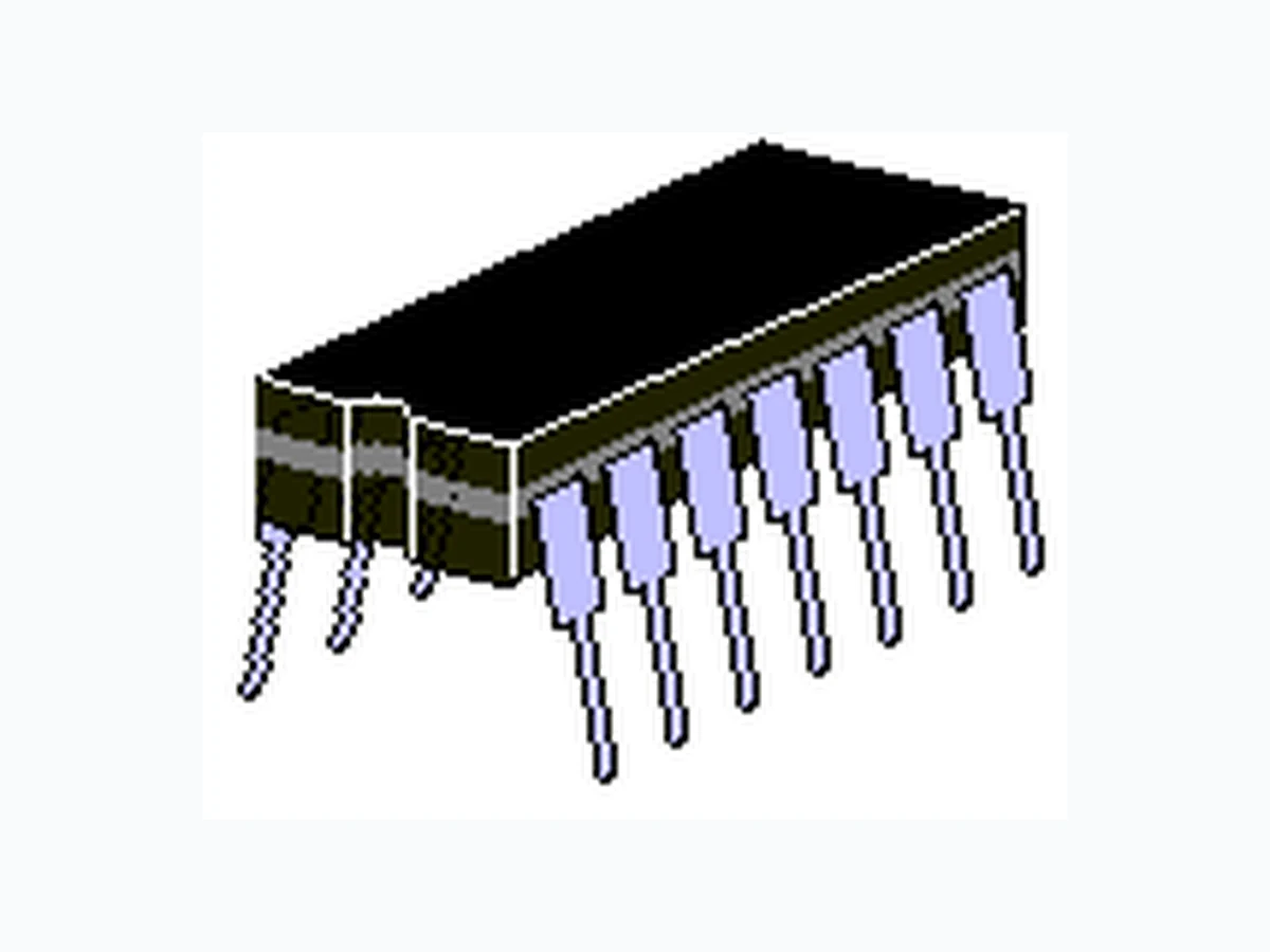
HiRel MQ, MX, MV, and SP Screening Options Microsemi Scottsdale Division 8700 E. Thomas Rd. PO Box 1390, Scottsdale, AZ 85252 USA, (480) 941-6300, Fax: (480) 947-1503 Page 1Copyright © 2007 3-27-2007 WWW.Microsemi .COM SCOTTSDALE DIVISION 6507A 6507A DESCRIPTION APPEARANCE These low capacitance diode arrays with common anode are multiple, discrete, isolated junctions fabricated by a planar process and mounted in a 10-PIN package for use as steering diodes prot ecting up to eight I/O ports from ESD, EFT, or surge by directing them to ground (see figure 1). This circ uit application is further complimented by the 1N6506 (separate data sheet) that has a common cathode. An external TVS diode may be added between the positive supply line and ground to prevent overvoltage on the supply rail. They may also be used in fast switching core-driver applications. This includes computers and peripheral equipment such as magnetic cores, thin-film memories, plated-wire memories, etc., as well as decoding or encoding applications. These arrays offer many advantages of integrated circuits such as high-density packaging and improved reliability. This is a result of fewer pick and place operations, smaller footprint, smaller weight, and elimination of various discrete packages that may not be as user friendly in PC board mounting. 14-PIN Ceramic DIP IMPORTANT: For the most current data, consult MICROSEMI’s website: http://www.microsemi.com FEATURES APPLICATIONS / BENEFITS
- Hermetic Ceramic Package
- Isolated Diodes to Eliminate Cross-Talk Voltages
- High Breakdown Voltage V BR > 60 V at 10 μA
- Low Leakage I R< 100nA at 40 V
- Low Capacitance C < 8.0 pF
- Options for screening in accordance with MIL-PRF- 19500/474 for JAN, JANTX, JANTXV, and JANS are available by adding MQ, MX, MV, or SP prefixes respectively to part numbers. For example, designate MX6507A for a JANTX screen.
- High Frequency Data Lines
- RS-232 & RS-422 Interface Networks
- Ethernet: 10 Base T
- Computer I/O Ports
- LAN
- Switching Core Drivers
- IEC 61000-4 Compatible (see circuit in figure 1) 61000-4-2 ESD: Air 15 kV, contact 8 kW 61000-4-4 (EFT): 40 A – 5/50 ns 61000-4-5 (surge): 12 A 8/20 μs MAXIMUM RATINGS MECHANICAL AND PACKAGING
- V BR Reverse Breakdown Voltage 60 V min (Notes 1 & 2)
- I O Continuous Forward Current of 300 mA (Notes 1 & 3)
- I FSM Forward Surge Current (tp=1/120 s) 500 mA (Note 1)
- 400 mW Power Dissipation per Junction @ 25 oC
- 600 mW Power Dissipation per Package @ 25 oC (Note 4)
- Operating Junction Temper ature range –65 to +150oC
- Storage Temperature range of –65 to +200 oC
- 14-PIN Ceramic DIP
- Weight 2.05 grams (approximate)
- Marking: Logo, part number, date code
- Pin #1 to the left of t he indent on top of package
- Carrier Tubes; 25 pcs (standard) NOTE 1: Each Diode NOTE 2: Pulsed: PW = 100 ms max; duty cycle <20% NOTE 3: Derate at 2.4 mA/ o C above +25 o C NOTE 4: Derate at 4.0 mW/ o C above +25 o C MAXIMUM FORWARD VOLTAGE VF1 IF = 100 mA (Note 1) MAXIMUM REVERSE CURRENT IR1 VR = 40 V MAXIMUM CAPACITANCE (PIN TO PIN) Ct VR = 0 V F = 1 MHz MAXIMUM FORWARD RECOVERY TIME tfr IF = 500 mA MAXIMUM REVERSE RECOVERY TIME trr IF = IR = 200 mA irr = 20 mA RL = 100 ohms PART NUMBER V μA pF ns ns 6507A 1 0.1 8.0 40 20 NOTE 1: Pulsed: PW = 300 us +/- 50 µs, duty cycle <2%, 90 µs after leading edge.
HiRel MQ, MX, MV, and SP Screening Options Microsemi Scottsdale Division 8700 E. Thomas Rd. PO Box 1390, Scottsdale, AZ 85252 USA, (480) 941-6300, Fax: (480) 947-1503 Page 2Copyright © 2007 3-27-2007 WWW.Microsemi .COM SCOTTSDALE DIVISION 6507A 6507A SYMBOLS & DEFINITIONS Symbol DEFINITION VBR Minimum Breakdown Voltage: The minimum voltage the device will exhibit at a specified current VF Maximum Forward Voltage: The maximum forward voltage the device will exhibit at a specified current IR Maximum Leakage Current: The maximum leakage current that will flow at the specified voltage and temperature IFSM Forward Surge Current: The peak forward surge current at a specified pulse width Ct Capacitance: The capacitance of the TVS as defined @ 0 volts at a frequency of 1 MHz and stated in picofarads SCHEMATIC PACKAGE DIMENSIONS CIRCUIT Supply rail (+VCC) GND (or -VCC) Steering Diode Application FIGURE 1 I/O Port