
6210125 CLARKE
Document overview
- Manufacturer or author: Provided By digicamel.com
- PDF pages: 12
Technical content
OPERATION & MAINTENANCE INSTRUCTIONS ORIGINAL INSTRUCTIONS DL 0821 - REV 11 BATTERY STARTER/CHARGER MODEL NO: BC125, BC190 PART NO: 6210125, 6210200
Parts & Service: 020 8988 7400 / E-mail: Parts@clarkeinternational.com or Service@clarkeinternational.com INTRODUCTION Thank you for purchasing this CLARKE Battery starter / charger. Please read this manual thoroughly, before attempting to operate, and carefully follow all instructions given. It is vitally important that ALL precautions are taken, as specified, which will not only provide protection for yourself and that of others around you, but will also ensure that the Battery Charger will give you long and satisfactory service. GUARANTEE This CLARKE product is guaranteed against faulty manufacture for a period of 12 months from the date of purchase. Please keep your receipt as proof of purchase. This guarantee is invalid if the product is found to have been abused or tampered with in any way, or not used for the purpose for which it was intended. Faulty goods should be returned to their place of purchase, no product can be returned to us without prior permission. This guarantee does not effect your statutory rights. ENVIRONMENTAL RECYCLING POLICY By purchasing this product, the customer is taking on the obligation to deal with its safe disposal in accordance with the WEEE regulations for the ethical disposal of the WEEE. This means that this product must not be disposed of with general household waste. It must be disposed of according to the laws governing Waste Electrical and Electronic Equipment (WEEE) at a recognised disposal facility.
Parts & Service: 020 8988 7400 / E-mail: Parts@clarkeinternational.com or Service@clarkeinternational.com SAFETY PRECAUTIONS 1. To prevent the battery from overheating and consequent damage, use the BOOST facility sparingly and do not exceed our recommendations. 2. Battery acid is highly co rrosive. If spillage occurs, wipe off immediately and wash copiously with water. Particularly avoid contact with the eyes. 3. Do not expose this unit to rain. 4. Never touch the negative an d positive leads together on this unit whilst it is switched on. 5. Never attempt any electrical or mech anical repair. If you have a problem with your machine contact your local stockist for service information. 6. Before charging ensure the battery te rminals are clean, and that the cells are filled with electrolyte to the correct level by adding distilled water where necessary. 7. Where appropriate we recommend th at the positive (+) lead to the battery is disconnected on the vehicle prior to charging. This will prevent damaging the vehicle electronics. 8. When charging is completed, ensure that the vehicle battery leads are secured to the correct terminals which should be clean and lightly smeared with petroleum jelly to prevent corrosion. Finally, re check the electrolyte level. WARNING: BECAUSE HIGHLY INFLAMMABLE HYDROGEN GAS IS RELEASED IN THE PROCESS OF BATTERY CHARGING, ALWA YS REMEMBER TO SWITCH OFF FIRST AND SO AVOID SPARKING, WHICH WILL OCCUR WHEN CONNECTING OR DISCONNECTING LIVE LEADS. WARNING: CERTAIN TYPES OF SEALED OR MAINTENANCE-FREE BATTERIES NEED EXTRA CARE WHEN CHARGING. PLEASE CONSULT BATTERY MANUFACTURERS INSTRUCTIONS BEFORE USING THIS UNIT. WARNING: SINCE TOXIC FUMES MAY BE RELEASED DURING BATTERY CHARGING, ONLY USE THIS UNIT IN A WELL VENTILATED AREA.
Parts & Service: 020 8988 7400 / E-mail: Parts@clarkeinternational.com or Service@clarkeinternational.com ELECTRICAL CONNECTIONS Before switching the product on, make sure that the voltage of your electricity supply is the same as that indicated on the rating plate. This product is designed to operate on 230VAC 50Hz. Connecting it to any other power source may cause damage. This product may be fitted with a non-rewireable plug. If it is necessary to change the fuse in the plug, the fuse cover must be refitted. If the fuse cover becomes lost or damaged, the plug must not be used until a suitable replacement is obtained. If the plug has to be changed because it is not suitable for your socket, or due to damage, it should be cut off and a replacement fitted, following the wiring instructions shown below. The old plug must be disposed of safely, as insertion into a mains socket could cause an electrical hazard. If the colours of the wires in the power cable of this product do not correspond with the markings on the terminals of your plug, proceed as follows.
- T h e Blue wire must be connected to the terminal marked N or coloured Black. T h e Brown wire must be connected to the terminal marked L or coloured Red. T h e Yellow and Green wire must be connected to the terminal marked E or or coloured Green. If in any doubt, consult a qualified electrician. DO NOT attempt any repairs yourself. WARNING: READ THESE ELECTRICAL SAFETY INSTRUCTIONS THOROUGHLY BEFORE CONNECTING THE PRODUCT TO THE MAINS SUPPLY. WARNING: THE WIRES IN THE POWER CABLE OF THIS PRODUCT ARE COLOURED IN ACCORDANCE WITH THE FOLLOWING CODE: BLUE = NEUTRAL BROWN = LIVE YELLOW AND GREEN = EARTH Plug must be BS1363/A approved. Always fit a 13 Amp fuse. Ensure that the outer sheath of the cable is firmly held by the clamp Neutral (Blue) Live (Brown) Earth (Green and Yellow)
Parts & Service: 020 8988 7400 / E-mail: Parts@clarkeinternational.com or Service@clarkeinternational.com OVERVIEW SPECIFICATIONS BC125 BC190 Input Voltage 230V AC @ 50 Hz 230V AC @ 50 Hz Max Rated Output Cur- rent Charging 20 Amps Starting 120 Amps Charging 38 Amps Starting 180 Amps Open Circuit Voltage MIN 12V/24V BOOST 12V/24V STARTING 12V/24V 10.05 / 22.54 Volts 10.40 / 23.46 Volts 10.58 / 23.97 Volts 10.63 / 23.76 Volts 11.24 / 25.49. Volts 11.43 / 25.70 Volts Boost Start Duty Cycle 3 Seconds ON / 120 sec- onds OFF - max 5 cycles
3 Seconds ON / 120 sec-
Output Protection Fuse 2 x 50A 2 x 110A Dimensions (D x W x H) 280 x 225 x 200 mm 280 x 225 x 200 mm Weight (kg) 7.7 8.8 Part Number 6210125 6210200
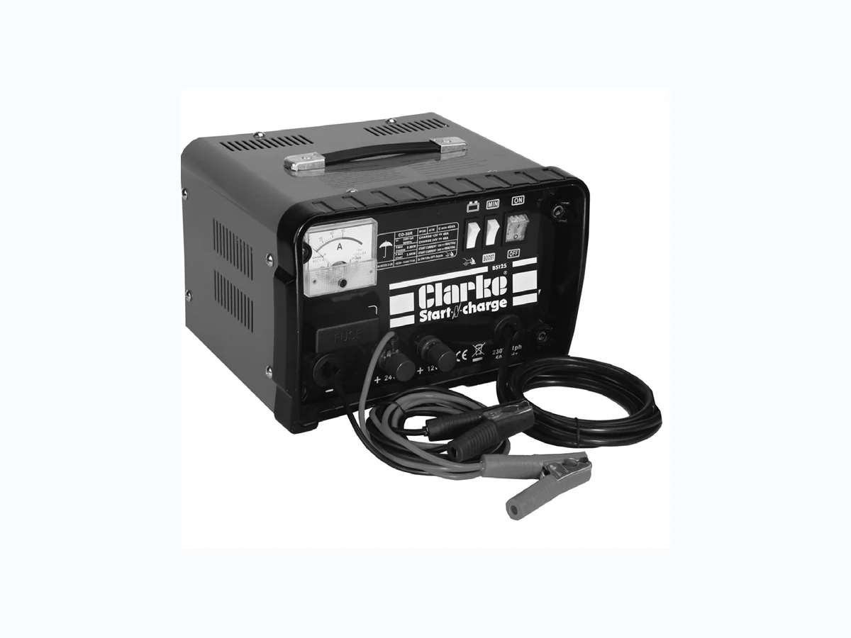
Parts & Service: 020 8988 7400 / E-mail: Parts@clarkeinternational.com or Service@clarkeinternational.com TO CHARGE THE BATTERY NOTES ON CHARGING PROCEDURE A complete charge is best done slow ly in order to protect your battery, so we recommend setting the MIN/BOOST switch to the MIN position. A complete charge may take up to 10 hours. If a low amperage reading (2 amps or less) is seen on the Ammeter gauge at either the MIN or BOOST setting, this may indicate that the battery is either (a) already fully charged or (b) at the end of its useful life and in need of replacement. Do not charge the battery for longer than is necessary. SETUP NOTE: Make sure that the battery cells are filled with electrolyte to the correct level by adding distilled water. 1. Check that the ON/OFF switch on the unit is in the OFF position. 2. Connect the RED, positive lead to ei ther the 12V or 24V terminal on the charger, as appropriate. 3. Remove the battery filler caps, wher e applicable, during charging, to prevent the build up of dangerous gases within the battery. WARNING: NEVER ATTEMPT TO RE-CHARGE NON-RECHARGEABLE BATTERIES. CAUTION: When charging a car battery in situ, we recommend that the non earthed lead on the battery is disconnected prior to charging (On most vehicles, this would be the RED, Positive lead - but check the vehicle handbook if you are unsure). This precaution is necessary as it is possible that damage could occur to any electronically controlled system fitted to the vehicle.
Parts & Service: 020 8988 7400 / E-mail: Parts@clarkeinternational.com or Service@clarkeinternational.com CONNECTING TO THE BATTERY 4. Connect the RED clamp to the positive (+) terminal. 5. Connect the BLACK clamp to the chassi s (or a suitable engine bolt) away from the battery and fuel line. 6. Switch the CHARGE/START swit ch to the CHARGE position. 7. Set the MIN/BOOST switch to the MIN position. This is suitable for charging most normal car batteries. 8. Switch the ON/OFF switch to ON, and charging will commence. You can increase the rate of charge by switching the MIN/BOOST switch to BOOST. 9. Keep the battery on charge until the Ammeter gauge reads less than 2 amps or has stopped moving down. WHEN CHARGING IS COMPLETE 10. Switch the ON/OFF switch to OFF. 11. ALWAYS disconnect the clamps in the following order - Black then Red. WARNING: IF THE LEADS ARE CONNECTED TO THE WRONG TERMINALS, A FLASH WILL OCCUR WHEN THE SECOND CLAMP IS CONNECTED. THIS MA Y CAUSE THE FUSE TO BLOW, THEREBY PROTECTING THE CHARGER AND BATTERY. IF THIS OCCURS, REMOVE THE BLACK COVER ON THE FRONT PANEL TO ACCESS THE FUSE.AFTER REPLACING THE FUSE ENSURE THE COVER IS REPLACED.
Parts & Service: 020 8988 7400 / E-mail: Parts@clarkeinternational.com or Service@clarkeinternational.com PROCEDURE FOR ENGINE STARTING NOTE: Make sure that the battery cells are filled with electrolyte to the correct level by adding distilled water. We recommend that before attempting to boost start, you charge the battery for 10-15 minutes. This will improve the chance of a first time start, particularly with bigger engines. When the battery is completely flat, you must charge the battery for 10-15 minutes before attempting to start, otherwise you may cause damage to the vehicle electronic systems. 1. Set the ON/OFF switch to the OFF position. 2. Connect the RED, positive lead to ei ther the 12V or 24V terminal on the charger, as appropriate. 3. Connect the RED clamp to the po sitive (+) battery terminal). 4. Connect the BLACK clamp to the chassi s (or a suitable engine bolt) away from the battery and fuel line. 5. Set the CHARGE/BOOST START sw itch to the BOOST position. 6. Switch the ON/OFF swit ch to the ON position. 7. Turn the ignition key to start the car. IMPORTANT: If the engine fails to start within 3 seconds stop immediately, and return the CHARGE/BOOST START switch to CHARGE position for a period of 120 seconds before retrying. Failure to do this could damage some vehicle electronic equipment, the battery, and possibly the unit which may invalidate your guarantee. THERMAL OVERLOAD These starter / chargers are provided with a Thermal Overload cut-out. Should the Duty Cycle be exceeded, or should the unit overheat for any reason, the thermal overload will intervene, shutting down the system. If this occurs, wait for 15 - 20 minutes, depending upon ambient temperature, before attempting to re-use. Once it has reset, the unit is ready for use once again.
Parts & Service: 020 8988 7400 / E-mail: Parts@clarkeinternational.com or Service@clarkeinternational.com DECLARATION OF CONFORMITY
Parts & Service: 020 8988 7400 / E-mail: Parts@clarkeinternational.com or Service@clarkeinternational.com PARTS DIAGRAM
Parts & Service: 020 8988 7400 / E-mail: Parts@clarkeinternational.com or Service@clarkeinternational.com PARTS LIST NO DESCRIPTION