

 Download PDF
2573_1810 SCHURTER
Document overview
- Manufacturer or author: Provided By digicamel.com
- PDF pages: 5
Technical content
Connectors (Inlets/Outlets) 2573https://www.schurter.com /PG07 Connectors IEC Appliance Inlet C8, Screw-on or Rivet Mounting, Front Side, Solder, PCB or Quick-connect Terminal See below: Approvals and Compliances 70° C
Description
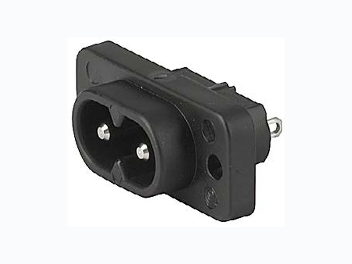
- Panel mount : Screw-on mounting , from front side - Appliance Inlet , Pin temperature 70 °C , Protection class II - Solder, Quick Connect or PCB Terminal - Solder terminals in horizontal or vertical orientation Characteristics - Contact pins are turned from solid material References We recommend for new applications the type 0720-FS Weblinks pdf datasheet, html-datasheet, General Product Information, Distributor- Stock-Check, Accessories, Detailed request for product Technical Data Ratings IEC 2.5 A / 250 VAC; 50 Hz Ratings UL/CSA 2.5 A / 250 VAC; 60 Hz Dielectric Strength > 3 kVAC between L-N > 1.5 kVAC between L/N-PE (1 min/50 Hz) Allowable Operation Tempe- rature -25 °C to 70 °C IP-Protection from front side IP 20 acc. to IEC 60529 Insulation cover Suitable for appliances with protection class II acc. to IEC 61140 Material: Housing PA6, black / grey / white, UL 94V-0 appliance inlet/-outlet C8 acc. to IEC 60320-1, UL 498, CSA C22.2 no. 42 (for cold conditions) pin-temperature 70 °C,
2.5 A, Protection Class II
Detailed information on product approvals, code requirements, usage instructions and detailed test conditions can be looked up in Details about Approvals Approvals The approval mark is used by the testing authorities to certify compliance with the safety requirements placed on electronic products. Approval Reference Type: 2573 Approval Logo Certificates Certification Body Description VDE Approvals VDE VDE Certificate Number: 40034368 UL Approvals UL UL File Number: E96454 CSA Approvals CSA CSA Certification Record: 27324 Product standards Product standards that are referenced Organization Design Standard Description Designed according to IEC 60320-1 Appliance couplers for household and similar general purposes Designed according to UL 498 Standard for Attachment Plugs and Receptacles Designed according to CSA C22.2 no. 42 General Use Receptacles, Attachment Plugs, and Similar Wiring Devices Application standards Application standards where the product can be used
Connectors (Inlets/Outlets)2573 https://www.schurter.com /PG07 Connectors Organization Design Standard Description Designed for applications acc. IEC/UL 60950 IEC 60950-1 includes the basic requirements for the safety of information technology equipment. Compliances The product complies with following Guide Lines Identification Details Initiator Description CE declaration of conformity SCHURTER AG The CE marking declares that the product complies with the applicable requirements laid down in the harmonisation of Community legislation on its affixing in accordance with EU Regulation 765/2008. RoHS SCHURTER AG EU Directive RoHS 2011/65/EU China RoHS SCHURTER AG The law SJ / T 11363-2006 (China RoHS) has been in force since 1 March 2007. It is similar to the EU directive RoHS. REACH SCHURTER AG On 1 June 2007, Regulation (EC) No 1907/2006 on the Registration, Evaluation, Authorization and Restriction of Chemicals 1 (abbreviated as "REACH") entered into force. Dimensions [mm] PCB terminal with additional solder terminal in orientation A (horizontal) 34.3 20.5 1.3 3.2 8.6 20.2 8.6 4 5.5 1.6 11.4E 11.9 0.8 6.5 8.6 +0.10 max. R4 3.2/M3 11.6 +0.20 20.4 +0.20 ±0.10 ±0.10 E = PCB terminal standard (additional solder): 6.9 mm E = PCB terminal short (additional solder): 0.6 mm E = PCB terminal long (additional solder): 15.9 mm E = PCB terminal standard: 6.6 mm E = PCB terminal short: 5.0 mm E = PCB terminal long: 7.7 mm
Connectors (Inlets/Outlets) 2573https://www.schurter.com /PG07 Connectors PCB terminal with additional solder terminal in orientation A (horizontal), screw-on mounting with pre-inserted nuts 34.3 20.5 1.3 8.6 20.2 M2.5 8.6 4 5.5 1.6 11.4E 11.9 0.8 6.5 8.6 +0.10 max. R4 3.2/M3 11.6 +0.20 20.4 +0.20 ±0.10 ±0.10 20.4 E = PCB terminal standard (additional solder): 6.9 mm E = PCB terminal short (additional solder): 0.6 mm E = PCB terminal long (additional solder): 15.9 mm E = PCB terminal standard: 6.6 mm E = PCB terminal short: 5.0 mm E = PCB terminal long: 7.7 mm 1) Insert nut Quick connect or solder terminal in orientation A (horizontal) or B (vertical) 34.3 20.5 3.2 20.2 7.6 4 5.5 11.4 11.9 max. R4 3.2/M3 11.6 +0.20 20.4 +0.20 ±0.10 E 1) 2) E = Solder terminal short: 11.0 mm E = Solder terminal long: 14.7 mm (only orientation B) E = Quick-connect terminal 2.8x0.8 mm: 17.0 mm E = Quick-connect terminal 4.8x0.8 mm: 15.5 mm (only orientation B) 1) Orientation of terminal: A 2) Orientation of terminal: B
Connectors (Inlets/Outlets)2573 https://www.schurter.com /PG07 Connectors Config. Code The characters are placeholders for the correspondingly keys of selections from the key tables. Type Configuration key protection class II X Terminal L Configuration key short solder terminal (L = 4.8 mm) long solder terminal (L = 8.5 mm) PCB-terminal standard (additional solder terminal) PCB-terminal short (additional solder terminal) PCB-terminal long (additional solder terminal) Blade terminal (2.8 x 0.8 mm) Blade terminal (4.8 x 0.8 mm) PCB-terminal (standard) A PCB-terminal (short) B PCB-terminal (long) C 2573 Terminal N Configuration key short solder terminal (L = 4.8 mm) 2 long solder terminal (L = 8.5 mm) 3 PCB-terminal standard (additional solder terminal) 4 PCB-terminal short (additional solder terminal) 5 Symbols similar as in table A Terminal N Configuration key PCB-terminal long (additional solder terminal) 6 Blade terminal (2.8 x 0.8 mm) 7 Blade terminal (4.8 x 0.8 mm) 8 PCB-terminal (standard) A PCB-terminal (short) B PCB-terminal (long) C Symbols similar as in table A 2573 Terminal Ground Configuration key without terminal 0 Symbols similar as in table A 2573 Color Configuration key Black A Grey B White D 2573 Style Configuration key flange with through holes 2 flange with through holes (special type) 7 2573 Dimension "S" Configuration key The dimension "S" is displayed in (1/10 mm). This information is also valid for the order code 2573 Orientation of Terminals Configuration key horizontal A vertical B
Connectors (Inlets/Outlets) 2573https://www.schurter.com /PG07 Connectors All Variants Terminals L / N Orientation of Ter- minals Color Style Config. Code Order Number short solder terminal (L = 4.8 mm) horizontal Black flange with through holes 2573-X-2200-A-200A 6160.0012 █ short solder terminal (L = 4.8 mm) vertical Black flange with through holes 2573-X-2200-A-200B 6160.0013 █ long solder terminal (L = 8.5 mm) vertical Black flange with through holes 2573-X-3300-A-200B 6160.0014 PCB-terminal short (additional solder terminal) horizontal Black flange with through holes (special type) 2573-X-5500-A-700A 6160.0015 Blade terminal (2.8 x 0.8 mm) horizontal Black flange with through holes 2573-X-7700-A-200A 6160.0016 The listet variants should be available from stock Other versions on request www.schurter.com/contact █ Most Popular. Availability for all products can be searched real-time:https://www.schurter.com/en/Stock-Check/Stock-Check-SCHURTER Packaging unit 100 Pcs The specifications, descriptions and illustrations indicated in this document are based on current information. All content is subject to modifications and amendments. Information furnished is believed to be accurate and reliable. However, users should independently evaluate the suitability and test each product selected for their own applications. 03.10.2018