
60EPU12 NELLSEMI
Document overview
- Manufacturer or author: Provided By www.digicamel.com(FREE DATASHEET DOWNLOAD SITE)
- PDF pages: 6
Technical content
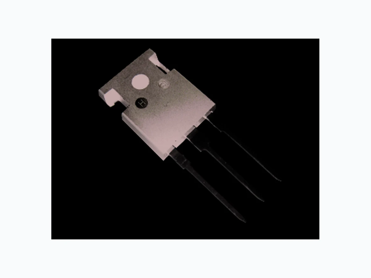
SEMICONDUCTOR 60EPU12 Series RoHS RoHS Ultrafast Soft Recovery Diode ABSOLUTE MAXIMUM RATINGS PARAMETER SYMBOL TEST CONDITIONS Cathode to anode voltage 1200 Continuous forward current lF(AV) TC = 60 °C 60 ASingle pulse forward current lFSM 570 Maximum repetitive forward current lFRM Square wave, 20 kHz Operating junction and storage temperatures - 55 to 150 ELECTRICAL SPECIFICATIONS (TJ = 25 unless otherwise specified)ºC PARAMETER SYMBOL TEST CONDITIONS Breakdown voltage, blocking voltage V Forward voltage Reverse leakage current Junction capacitance PRODUCT SUMMARY IF(AV) trr VR 45 ns 60 A 1200 V pF µA Nell High Power Products FRED VR T , Tj Stg TC = 25 °C 100 V VF lR CT l = 100µAR 1200 - - l = 60AF l = 120AF l = 60A, T = 125°CF J V = R V ratedR T = 150°C, J V = V ratedR R V = 200VR 2.3 500 Page 1 of 6www.nellsemi.com MIN. TYP. MAX. UNITS VALUES UNITS TO-247AC modified Cathode Anode Anode Cathode Anode to base Cathode to base 1 3 TO-247AB 60EPU12 60APU12
FEATURES
150 °C operating junction temperature Designed and qualified for industrial level BENEFITS Reduced RFI and EMI Higher frequency operation Reduced snubbing Reduced parts count DESCRIPTION/APPLICATIONS Planar FRED Chip Anti-parallel diode for switching mode power supply and inverters. Free wheeling diode for motor controllers and inverters. Snubber diode Uninterruptible power supply (UPS) Induction heating HF welder High speed rectifiers V R Series inductance LS Measure lead to lead 5mm from - 2.0 package body - 10 - nH 2.1 - 3.0 1.0 60A / 1200V
DYNAMIC RECOVERY CHARACTERISTICS (TJ = 25 unless otherwise specified)ºC MIN. TYP. MAX. UNITS Reverse recovery time ns IF = 60 A dI /dt = 200 A/µsF VR = 800 V Peak recovery current A Reverse recovery charge nC 330 - - 430 I = 0.5A, I = 1A, I =0.25A F R RR (RG#1 CKT) 65 70- trr lRRM Qrr I = 1A, dI /dt = 200 A/µs, V =30VF F R T = 25°CJ T = 125°CJ T = 25°CJ T = 125°CJ T = 25°CJ T = 125°CJ 2800 650 PARAMETER SYMBOL TEST CONDITIONS SEMICONDUCTOR RoHS RoHS Nell High Power Products Page 2 of 6www.nellsemi.com 60EPU12 Series THERMAL - MECHANICAL SPECIFICATIONS MIN. TYP. MAX. UNITS Thermal resistance, junction to case °C/W Thermal resistance, case to heatsink Mounting surface, flat, smooth and greased Weight Mounting torque N ⋅ m Marking device Case style TO-247AC modified Case style TO-247AC ( )5 (10) (lbf . in) 0.6 1.2- 60EPU12 60APU12 RthJC RthCS 0.40 0.5 5.5 0.2 - g oz. PARAMETER SYMBOL TEST CONDITIONS Thermal resistance, junction to ambient RthJA - 40
-5 10 Fig.1 Maximum effective transient thermal impedance, junction-to-case vs. pulse duration 0.45 0.40 0.35 0.30 0.25 0.20 0.15 0.10 0.05 0.5 0.1 0.3 0.7 0.05 Note: D = 0.9 , thermal impedance- (°C/W)ZθJC -4 10 -3 10 -2 10 -1 10 1 Single pulse Rectangular pulse duration (seconds) Duty Factor D = t /t1 2 Peak T = P x Z + TJ DM θJC C PDM 30A 60A 120A 400 300 200 100 200 180 160 140 120 100 7000 6000 5000 4000 3000 2000 1000 120A 60A 30A120A 30A 60A Fig.2 Forward current vs. forward voltage T = 175°CJ T = 125°CJ T = 25°CJ T = -55°CJ Forward current-l (A) F Anode-to-cathode voltage-V (V)F 500 8006004002000 1000 1200 T = 125°CJ V = 800VR Fig3. Reverse recovery time vs. current rate of change Reverse recovery time-t (ns)rr Current rate of change-di /dt(A/µs)F T = 125°CJ V = 800VR Fig.4 Reverse recovery charge vs. current rate of change Reverse recovery charge-Q (nC)rr Current rate of change-di /dt(A/µs)F 8006004002000 1000 1200 Current rate of change-di /dt(A/µs)F Reverse recovery current-l (A)RRM 8006004002000 1000 1200 Fig.5 Reverse recovery current vs. current rate of change T = 125°CJ V = 800VR SEMICONDUCTOR RoHS RoHS Nell High Power Products Page 3 of 6www.nellsemi.com 60EPU12 Series
Duty cycle = 0.5 10090807060403020100 1.2 0.8 0.6 0.4 0.2 300 250 200 150 100 Fig.6 Dynamic parameters vs. junction temperature Junction temperature-T (°C)J Dynamic parameters-K f (Normalized to 1000A/µs ) 1501251007550250 Qrr lRRM trr l (A)F(AV) Case temperature (°C) Fig.7 Maximum average forward current vs. case temperature 150 125 100 175 T = 150°CJ Fig.8 Junction capacitance vs. reverse voltage Reverse voltage-V (V)R Junction capacitance-C (pF)J 200100101
60 E P U 12
- Current rating (60 = 60A) 3 - TO-247AC (Modified) or TO-247AB Voltage R a t ing (12 = 1200 V)5 Ultrafast Recovery Single Diode Ordering Information Table Device code E = 2 pins A = 3 pins SEMICONDUCTOR RoHS RoHS Nell High Power Products Page 4 of 6www.nellsemi.com 60EPU12 Series DC
Fig.9 Reverse recovery parameter test circuit Fig.10 Reverse recovery waveform and definitions SEMICONDUCTOR RoHS RoHS Nell High Power Products Page 5 of 6www.nellsemi.com 60EPU12 Series
Page 6 of 6www.nellsemi.com 2.21 (0.087) 2.59 (0.102) 0.40 (0.016) 0.79 (0.031) 1.49 (0.059) 2.49 (0.098) 4.69 (0.185) 5.31 (0.209) 10.90 (0.43) (TYP.) 1.01 (0.040) 1.40 (0.055) 19.81 (0.780) 20.32 (0.800) 4.50 (0.177)Max 20.80 (0.819) 21.46 (0.845) 16.15 (0.242) 15.49 (0.610) 16.26 (0.640) 5.38 (0.212) 6.20 (0.244) 3.55 (0.138) 3.81 (0.150) 1.65 (0.065) 2.13 (0.084) (TYP.) 2.21 (0.087) 2.59 (0.102) 0.40 (0.016) 0.79 (0.031) 1.49 (0.059) 2.49 (0.098) 4.69 (0.185) 5.31 (0.209) 1.01 (0.040) 1.40 (0.055) (TYP.) 1.01 (0.040) 1.40 (0.055) 19.81 (0.780) 20.32 (0.800) 4.50 (0.177)Max 20.80 (0.819) 21.46 (0.845) 16.15 (0.242) 15.49 (0.610) 16.26 (0.640) 5.38 (0.212) 6.20 (0.244) 3.55 (0.138) 3.81 (0.150) 2.87 (0.113) 3.12 (0.123) 1.65 (0.065) 2.13 (0.084) (TYP.) Conforms to JEDEC Outline TO-247AC (Modified) Dimensions in millimeters and (inches) Conforms to JEDEC Outline TO-247AB Dimensions in millimeters and (inches) Cathode Anode Anode Anode 1 3 60APU12 3 pins 60EPU12 2 pins CATHODE TO BASE CATHODE TO BASE 1 2 3 1 2 3 60EPU12 Series