

 Download PDF
DATASHEET SEARCH SITE
Document overview
- PDF pages: 12
Technical content
Page 1
Series 8016 – .075" x .130" x .150" Grid Pattern
FEATURES
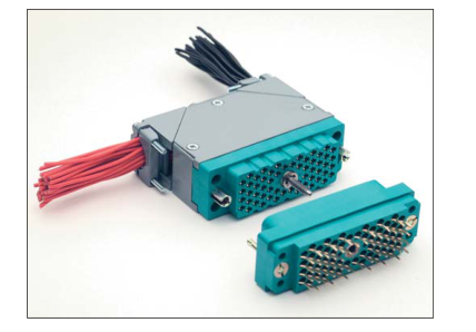
- Available in five sizes: 20, 38, 56, 90 and 120 contacts
- Insertable / removable Varilok contacts
- Crimp, solder, solderless wrap, and taper tab terminations
- Exceptional versatility: all hardware can be mounted on plug or receptacle (see ordering code)
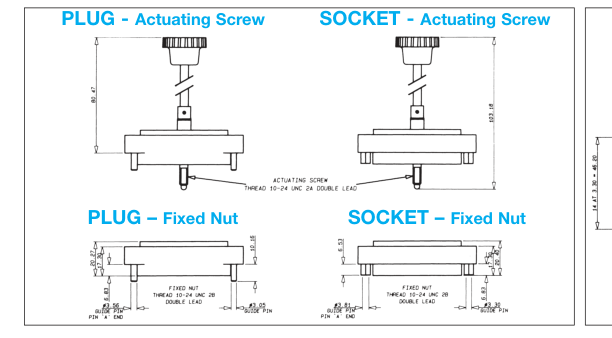
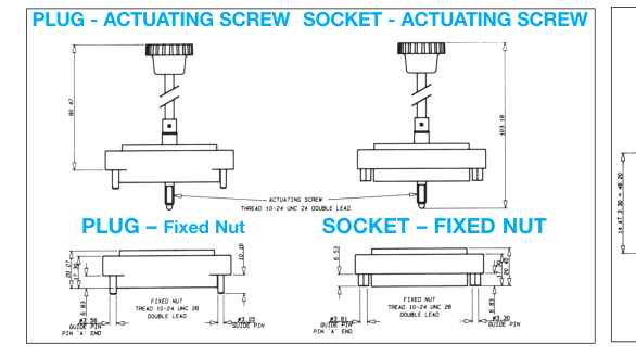
- Actuating screw facilitates mating and unmating, locks mated connectors together
- Polarizing hardware can be set to any of six positions at factory; can also be reset by user (see polarizing code)
- Optional cover with top or side cable entry and clamp
- Optional cable strain relief clamp with adjustable strap for large or small cable bundles (fits on sizes 38 and 56)
- Plug and receptacle contacts are protected from mishandling
- Guide pins and sockets ensure correct alignment when mating
- Aluminum covers
- CSA acceptable polyester material
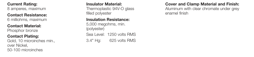
TECHNICAL SPECIFICATIONS
Page 2
Series 8016 – Basic Components
CONECTORS:
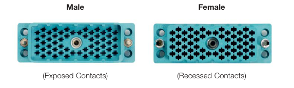
Male, Jackscrew
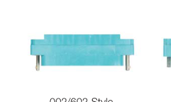
Male, Fixed Nut
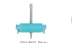
001/601 Style
002/602 Style
COVERS:
Female, Fixed Nut
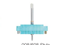
Female, Jackscrew
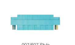
007/607 Style
008/608 Style
Side Opening
Top Opening
Top/side Opening
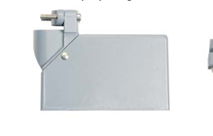
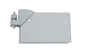
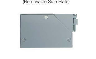
CONTACTS:
Crimp
Solder Tab
Wire Wrap
Wire Wrap
Wire Wrap
Solder
14.4mm
19.3mm
.567
217 Style
218 Style
750 Style
296 Style
504 Style
Page 3
Series 8016 – Rectangular Connector – 20 Contact
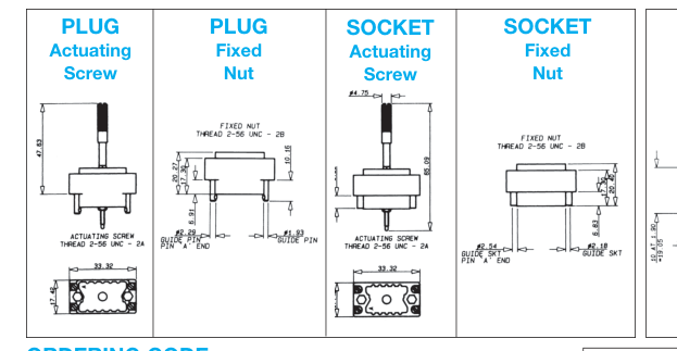
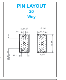
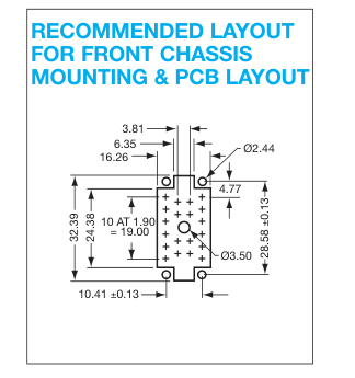
ORDERING CODE
00 8016
020 217
601
| Series Number of Number Contacts | See table below |
| Contact Termination *000 = Contacts not fitted and ordered separately, see page 25 for full list of options 217 = Solder 0.098" x 2.49mm 218 = Wire Wrap – 0.025 x 0.050 x 0.567" / 0.64 x 1.27 x 14.4mm 296 = Wire Wrap – 0.025 x 0.026 x 0.579" / 0.64 x 0.66 x 14.7mm 504 = Solder Tail – 750 = Wire Wrap – 0.025 x 0.050 x 0.760" / 0.64 x 1.27 x 19.3mm | |
Prefix
See page 26 for assembly tools.
\*Crimp contacts always ordered separately. See page 25 for details.
| 20 CONTACTS | COVER | |||||||
| Insulator Body Type | Basic P/N* | Color | Hardware **Thread | No Cover | Top Std Clamp | Side Std Clamp | Actuating Screw | Fixed Nut |
| Male | 00 8016 020 000 XXX | Green | UNC | 601 | 603 | 604 | Y | N |
| Male | 00 8016 020 000 XXX | Green | UNC | 602 | 605 | 606 | N | Y |
| Male | 00 8016 020 000 XXX | Gray | UNC | 001 | 903 | 904 | Y | N |
| Male | 00 8016 020 000 XXX | Gray | UNC | 002 | 905 | 906 | N | Y |
| Female | 00 8016 020 000 XXX | Green | UNC | 608 | 609 | 610 | Y | N |
| Female | 00 8016 020 000 XXX | Green | UNC | 607 | 611 | 612 | N | Y |
| Female | 00 8016 020 000 XXX | Gray | UNC | 008 | 909 | 910 | Y | N |
| Female | 00 8016 020 000 XXX | Gray | UNC | 007 | 911 | 912 | N | Y |
\*Select the column desired and replace the XXX with the numbers from column. \*\*United Course Thread
Page 4
Series 8016 – Rectangular Connector – 38 Contact
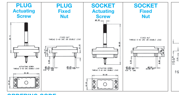
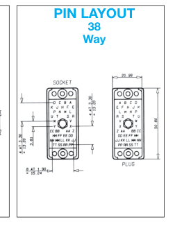
ORDERING CODE
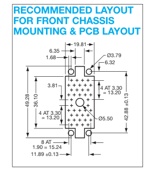
00 8016
038 217
601
| Series Number of Number Contacts | See table below |
| Contact Termination *000 = Contacts not fitted and ordered separately, see page 25 for full list of options 217 = Solder 0.098" x 2.49mm 218 = Wire Wrap – 0.025 x 0.050 x 0.567" / 0.64 x 1.27 x 14.4mm 296 = Wire Wrap – 0.025 x 0.026 x 0.579" / 0.64 x 0.66 x 14.7mm 504 = Solder Tail – 750 = Wire Wrap – 0.025 x 0.050 x 0.760" / 0.64 x 1.27 x 19.3mm | |
Prefix
See page 26 for assembly tools.
\*Crimp contacts always ordered separately. See page 25 for details.
| 38 CONTACTS | COVER | |||||||||||
| Insulator Body Type | Basic P/N* | Color | Hardware **Thread | No Cover | Top Std Clamp | Side Std Clamp | Top Lge Clamp | Side Lge Clamp | Top EX Lge Clamp | Side EX Lge Clamp | Actuating Screw | Fixed Nut |
| Male | 00 8016 038 000 XXX | Green | UNC | 601 | 603 | 604 | 619 | 620 | 631 | 632 | Y | N |
| Male | 00 8016 038 000 XXX | Green | UNC | 602 | 605 | 606 | 621 | 622 | 633 | 634 | N | Y |
| Male | 00 8016 038 000 XXX | Gray | UNC | 001 | 903 | 904 | 919 | 920 | 931 | 932 | Y | N |
| Male | 00 8016 038 000 XXX | Gray | UNC | 002 | 905 | 906 | 921 | 922 | 933 | 934 | N | Y |
| Female | 00 8016 038 000 XXX | Green | UNC | 608 | 609 | 610 | 623 | 624 | 635 | 636 | Y | N |
| Female | 00 8016 038 000 XXX | Green | UNC | 607 | 611 | 612 | 625 | 626 | 637 | 638 | N | Y |
| Female | 00 8016 038 000 XXX | Gray | UNC | 008 | 909 | 910 | 923 | 924 | 935 | 936 | Y | N |
| Female | 00 8016 038 000 XXX | Gray | UNC | 007 | 911 | 912 | 925 | 926 | 937 | 938 | N | Y |
\*Select the column desired and replace the XXX with the numbers from column. \*\*United Course Thread
Page 5
Series 8016 – Rectangular Connector – 56 Contact
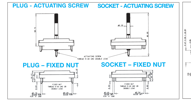
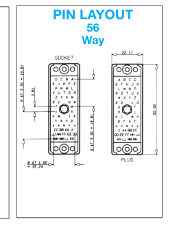
ORDERING CODE
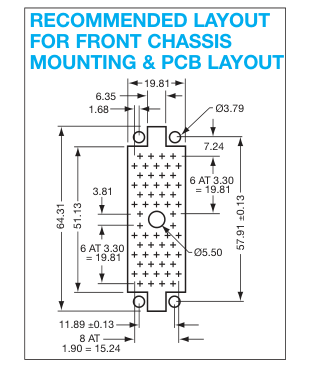
00 8016
056 217
601
| Series Number of Number Contacts | See table below |
| Contact Termination *000 = Contacts not fitted and ordered separately, see page 25 for full list of options 217 = Solder 0.098" x 2.49mm 218 = Wire Wrap – 0.025 x 0.050 x 0.567" / 0.64 x 1.27 x 14.4mm 296 = Wire Wrap – 0.025 x 0.026 x 0.579" / 0.64 x 0.66 x 14.7mm 504 = Solder Tail – 750 = Wire Wrap – 0.025 x 0.050 x 0.760" / 0.64 x 1.27 x 19.3mm | |
Prefix
\*Crimp contacts always ordered separately. See page 25 for details.
See page 26 for assembly tools.
| 56 CONTACTS | ||||||
| Insulator Body Type | Basic P/N* | Color | Hardware **Thread | No Cover | Actuating Screw | Fixed Nut |
| Male | 00 8016 056 000 XXX | Green | UNC | 601 | Y | N |
| Male | 00 8016 056 000 XXX | Green | UNC | 602 | N | Y |
| Male | 00 8016 056 000 XXX | Gray | UNC | 001 | Y | N |
| Male | 00 8016 056 000 XXX | Gray | UNC | 002 | N | Y |
| Female | 00 8016 056 000 XXX | Green | UNC | 608 | Y | N |
| Female | 00 8016 056 000 XXX | Green | UNC | 607 | N | Y |
| Female | 00 8016 056 000 XXX | Gray | UNC | 008 | Y | N |
| Female | 00 8016 056 000 XXX | Gray | UNC | 007 | N | Y |
\*Select the column desired and replace the XXX with the numbers from column. \*\*United Course Thread
Page 6
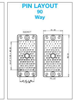
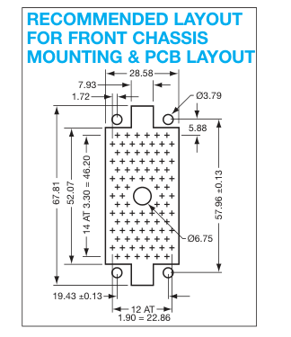
Series 8016 – Rectangular Connector – 90 Contact
ORDERING CODE
00 8016
090 217
601
| Series Number of Number Contacts | See table below |
| Contact Termination *000 = Contacts not fitted and ordered separately, see page 25 for full list of options 217 = Solder 0.098" x 2.49mm 218 = Wire Wrap – 0.025 x 0.050 x 0.567" / 0.64 x 1.27 x 14.4mm 296 = Wire Wrap – 0.025 x 0.026 x 0.579" / 0.64 x 0.66 x 14.7mm 504 = Solder Tail – 750 = Wire Wrap – 0.025 x 0.050 x 0.760" / 0.64 x 1.27 x 19.3mm | |
Prefix
\*Crimp contacts always ordered separately. See page 25 for details.
See page 26 for assembly tools.
| 90 CONTACTS | COVER | |||||||||
| Insulator Body Type | Basic P/N* | Color | Hardware **Thread | No Cover | Top Lge Clamp | Side Lge Clamp | Top EX Lge Clamp | Side EX Lge Clamp | Actuating Screw | Fixed Nut |
| Male | 00 8016 090 000 XXX | Green | UNC | 601 | 603 | 604 | 631 | 632 | Y | N |
| Male | 00 8016 090 000 XXX | Green | UNC | 602 | 605 | 606 | 633 | 634 | N | Y |
| Male | 00 8016 090 000 XXX | Gray | UNC | 001 | 903 | 904 | 931 | 932 | Y | N |
| Male | 00 8016 090 000 XXX | Gray | UNC | 002 | 905 | 906 | 933 | 934 | N | Y |
| Female | 00 8016 090 000 XXX | Green | UNC | 608 | 609 | 610 | 635 | 636 | Y | N |
| Female | 00 8016 090 000 XXX | Green | UNC | 607 | 611 | 612 | 637 | 638 | N | Y |
| Female | 00 8016 090 000 XXX | Gray | UNC | 008 | 909 | 910 | 935 | 936 | Y | N |
| Female | 00 8016 090 000 XXX | Gray | UNC | 007 | 911 | 912 | 937 | 938 | N | Y |
\*Select the column desired and replace the XXX with the numbers from column. \*\*United Course Thread
Page 7
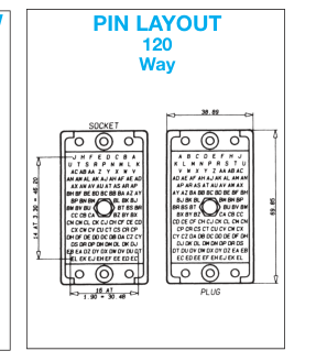
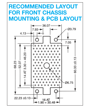
Series 8016 – Rectangular Connector – 120 Contact
ORDERING CODE
00 8016
120 217
601
| Series Number of Number Contacts | See table below |
| Contact Termination *000 = Contacts not fitted and ordered separately, see page 25 for full list of options 217 = Solder 0.098" x 2.49mm 218 = Wire Wrap – 0.025 x 0.050 x 0.567" / 0.64 x 1.27 x 14.4mm 296 = Wire Wrap – 0.025 x 0.026 x 0.579" / 0.64 x 0.66 x 14.7mm 504 = Solder Tail – 750 = Wire Wrap – 0.025 x 0.050 x 0.760" / 0.64 x 1.27 x 19.3mm | |
Prefix
\*Crimp contacts always ordered separately. See page 25 for details.
See page 26 for assembly tools.
| 120 CONTACTS | COVER | |||||||
| Insulator Body Type | Basic P/N* | Color | Hardware **Thread | No Cover | Top Lge Clamp | Side Lge Clamp | Actuating Screw | Fixed Nut |
| Male | 00 8016 120 000 XXX | Green | UNC | 601 | 603 | 604 | Y | N |
| Male | 00 8016 120 000 XXX | Green | UNC | 602 | 605 | 606 | N | Y |
| Male | 00 8016 120 000 XXX | Gray | UNC | 001 | N/A | N/A | Y | N |
| Male | 00 8016 120 000 XXX | Gray | UNC | 002 | N/A | N/A | N | Y |
| Female | 00 8016 120 000 XXX | Green | UNC | 608 | 609 | 610 | Y | N |
| Female | 00 8016 120 000 XXX | Green | UNC | 607 | 611 | 612 | N | Y |
| Female | 00 8016 120 000 XXX | Gray | UNC | 008 | N/A | N/A | Y | N |
| Female | 00 8016 120 000 XXX | Gray | UNC | 007 | N/A | N/A | N | Y |
\*Select the column desired and replace the XXX with the numbers from column. \*\*United Course Thread
Page 8
Series 8016 Covers
| Part Number | For Size | Hardware Threads | Cable Entance | Clamp Type | Size mm (inches) |
|---|---|---|---|---|---|
| 30 8016 9829 00 000 | 20 | Metric | Side | Standard | 11.53 (0.454) Dia |
| 30 8016 9831 00 000 | 20 | Metric | Top | Standard | 11.53 (0.454) Dia |
| 30 8016 0200 00 415 | 20 | UNC | 45 | Standard | 5 x 10 (0.197 x 0.394) min |
| 30 8016 9821 00 000 | 38 | Metric | Side | Standard | 16.51 x 12.70 (0.650 x 0.500) |
| 30 8016 9822 00 000 | 38 | Metric | Top | Standard | 16.51 x 12.70 (0.650 x 0.500) |
| 30 8016 9825 00 000 | 38 | Metric | Side | Large | 16.51 x 15.44 (0.650 x 0.608) |
| 30 8016 9826 00 000 | 38 | Metric | Top | Large | 16.51 x 15.44 (0.650 x 0.608) |
| 30 8016 9838 00 000 | 38 | Metric | Side | Ex-Large | 20.83 x 15.60 (0.820 x 0.614) |
| 30 8016 9839 00 000 | 38 | Metric | Top | Ex-Large | 20.83 x 15.60 (0.820 x 0.614) |
| 30 8016 0560 00 413 | 56 | UNC | Top/Side | Standard | 6 x 14 (0.236 x 0.551) min |
| 30 8016 0560 00 415 | 56 | UNC | 45 | Standard | 6 x 14 (0.236 x 0.551) min |
| 30 8016 9832 00 000 | 90 | Metric | Side | Large | 20.32 (0.800) Dia |
| 30 8016 9833 00 000 | 90 | Metric | Top | Large | 20.32 (0.800) Dia |
| 30 8016 9843 00 000 | 90 | Metric | Side | Ex-Large | 25.40 x 20.32 (1.00 x 0.800) |
| 30 8016 9844 00 000 | 90 | Metric | Top | Ex-Large | 25.40 x 20.32 (1.00 x 0.800) |
| 30 8016 9834 00 000 | 120 | Metric | Side | Large | 20.32 x 27.43 (0.800 x 1.080) |
| 30 8016 9835 00 000 | 120 | Metric | Top | Large | 20.32 x 27.43 (0.800 x 1.080) |
Page 9
Series 8016 Covers
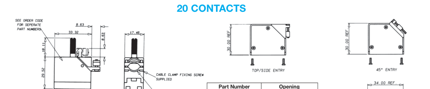
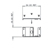
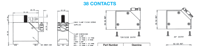
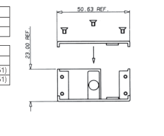
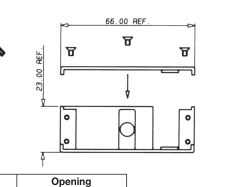
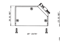
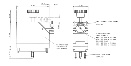
CLAMPING AND COVER DIMENSIONS
OPTIONAL REMOVABLE SIDE PLATE COVER
| Part Number | Opening |
|---|---|
| 308016020000413 | Side/Top |
| 308016020000415 | 45º |
| CLAMP | |
| Minimum Size | Maximum Size |
| 5 x 10 (0.197 x 0.394) | 10 x 10 (0.394 x 0.394) |
| 5 x 10 (0.197 x 0.394) | 10 x 10 (0.394 x 0.394) |
| Part Number | Opening |
|---|---|
| 308016038000413 | Side/Top |
| 308016038000415 | 45º |
| CLAMP | |
| Minimum Size | Maximum Size |
| 6 x 14 (0.236 x 0.551) | 17 x 14 (0.669 x 0.551) |
| 6 x 14 (0.236 x 0.551) | 17 x 14 (0.669 x 0.551) |

| Part Number | Opening |
|---|---|
| 308016056000413 | Side/Top |
| 308016056000415 | 45º |
| CLAMP | |
| Minimum Size | Maximum Size |
| 6 x 14 (0.236 x 0.551) | 17 x 14 (0.669 x 0.551) |
| 6 x 14 (0.236 x 0.551) | 17 x 14 (0.669 x 0.551) |
Page 10
Series 8016 Covers
CLAMPING AND COVER DIMENSIONS
90 CONTACTS
120 CONTACTS
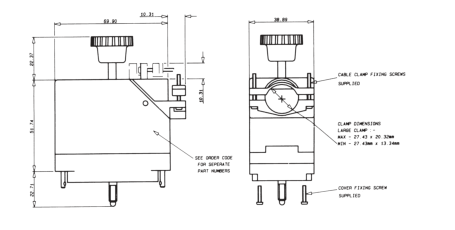
See page 21 for part numbers
Page 11
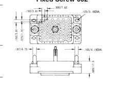
Series 8017
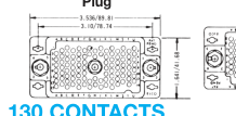
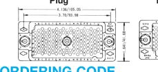
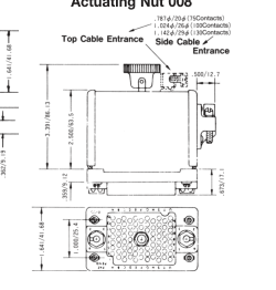
75/100/130 CONTACTS
75 CONTACTS
Plug with
Plug with
Plug
Receptacle
Actuating Screw 001
Fixed Screw 002
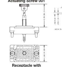
100 CONTACTS
Receptacle
Plug
Receptacle with
Receptacle
Plug
Fixed Nut 007
Actuating Nut 008
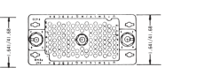
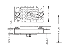
ORDERING CODE
00 8017
XXX XXX
0XX
| refix Series Number of Number Positions 75, 100, 130 | See Variatio Code |
| Contact Code 217 = Solder 0.098" x 2.49mm – 60 8017 0513 00 339 218 = Wire Wrap – 0.025 x 0.050 x 0.567" / 0.64 x 1.27 x 14.4mm 60 8017 0613 00 339 750 = Wire Wrap – 0.025 x 0.050 x 0.760" / 0.64 x 1.27 x 19.3mm 60 8017 0623 00 339 296 = Wire Wrap – 0.025 x 0.026 x 0.579" / 0.64 x 0.66 x 14.7mm 60 8017 0633 00 339 313 = Wire Crimp (Contacts Loose) – 60 8017 0313 00 339 Must be ordered separately 323 = Wire Crimp (1800 Contacts on a Reel) – 60 8017 0323 99 339 Must be ordered separately | |
RECOMMENDED CHASSIS LAYOUT
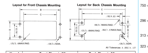
| No. of Pos. | Front Chassis Mtg. | Back Chassis Mtg. | ||||
| B | C | D | B | C | D | |
| 75 | 2.500/63.50 | 1.953/49.61 | 1.437/36.50 | 2.500/63.50 | 2.953/75.00 | 1.656/42.06 |
| 100 | 3.100/78.74 | 2.546/64.67 | 1.437/36.50 | 3.100/78.74 | 3.562/90.47 | 1.656/42.06 |
| 130 | 3.700/93.98 | 3.156/80.16 | 1.437/36.50 | 3.700/93.98 | 4.156/105.56 | 1.656/42.06 |
CONNECTOR PLUG
AND RECEPTACLE
COMBINATIONS
Dimensions inches/mm
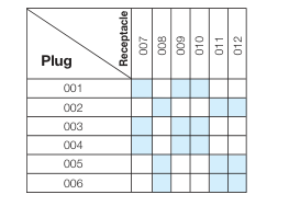
VARIATION CODE
| Insulator Body Type | Variation Code No. | Cover & Cable Entrance | Fixed Nut | Actuating Nut |
|---|---|---|---|---|
| Receptacle | 007 | No | Yes | No |
| 008 | No | No | Yes | |
| 009 | Top | Yes | No | |
| 010 | Side | Yes | No | |
| 011 | Top | No | Yes | |
| 012 | Side | No | Yes |
| Insulator Body Type | Variation Code No. | Cover & Cable Entrance | Actuating Screw | Fixed Screw |
|---|---|---|---|---|
| Plug | 001 | No | Yes | No |
| 002 | No | No | Yes | |
| 003 | Top | Yes | No | |
| 004 | Side | Yes | No | |
| 005 | Top | No | Yes | |
| 006 | Side | No | Yes |
Page 12
Varilok®
Loose Contacts
Varilok® connectors can be specified as either fully loaded, to
of separately specified and ordered contacts. The table
include the connector body and a variety of pre-loaded
below details the various loose contacts available.
contact termination types or the empty body and a selection
| Contact Style | Description | Plating Specification | Order Code |
|---|---|---|---|
| * Ordered separately | Crimp Contact Loose | 0.25µM Gold All Over (Standard) 0.25µM Gold Nose & Tail (Optional) | 60 8017 0313 00 339 60 8017 0313 00 042 |
| Ordered separately | Crimp Contact End Carrier (1800 Contacts per reel) | 0.25µM Gold All Over (Standard) 0.25µM Gold Nose & Tail (Optional) 0.25µM Gold All Over (Standard) 0.25µM Gold Nose & Tail (Optional) | 60 8017 0323 99 339 60 8017 0323 99 042 60 8017 0323 00 339 60 8017 0323 00 042 |
| Tail Section – 2.49 x 0.61 (0.098 x 0.024) * If fitted type 217 | Solder Tag Contact | 0.25µM Gold All Over (Standard) | 60 8017 0513 00 339 |
| Tail Section – 1.27 x 0.63 (0.025 x 0.005) If fitted type 218 | 14.4mm Maxiwrap Contact | 0.25µM Gold All Over (Standard) | 60 8017 0613 00 339 |
| Tail Section – 1.27 x 0.63 (0.025 x 0.005) If fitted type 750 | 19.3mm Maxiwrap Contact | 0.25µM Gold All Over (Standard) | 60 8017 0623 00 339 |
| Tail Section – 0.635 x 0.63 (0.025 x 0.005) If fitted type 296 | 14.0 Miniwrap Contact | 0.25µM Gold All Over (Standard) | 60 8017 0633 00 339 |
| Tail Section – 0.635 x 0.63 (0.025 x 0.005) * If fitted type 504 | 4.3mm PC Solder Contact for ø 1.00 mm P.T.H. | 0.25µM Gold All Over (Standard) | 60 8017 0663 00 339 |
\* Indicates standard contact \*\* Order code to be used when purchasing through a USA source.
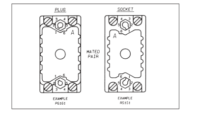
CONNECTOR POLARIZATION
Varicon® 8016 Series connectors are designed with an integral
polarizing system to ensure in high density environments that the
correct halves are mated together.
As a factory standard, male plugs are set to the code PG1G1, with
the female receptacles being set to the opposite matching code
RS1S1.
Customers who need to change the standard polarization to
another position can do so by using hand tool 06 1989 02 00
0000, or, by ordering the connectors with the required polarization
(eg: PG1G4 or RS2S5, etc) When ordering a different polarization
from normal, the polarization is called out at the end of the part
number (Ex: 00 8016 056 000 601PG2G4, etc).
ORDERING CODE
P
G
Type of Connector Half
Location Side (Large Dia.)
Plug = P
1 through 6
Guide Pin = G
Socket = R
Guide Socket = S
Plating code 343 = 0.50 µm Gold all over
1
G
1
Positions
Location Side
Positions
(Small Dia.)
1 through 6
Guide Pin = G Guide Socket = S